brake NISSAN QUEST 2004 V42 / 3.G Owners Manual
[x] Cancel search | Manufacturer: NISSAN, Model Year: 2004, Model line: QUEST, Model: NISSAN QUEST 2004 V42 / 3.GPages: 320, PDF Size: 5.6 MB
Page 14 of 320

1. Power steering fluid reservoir (P. 8-13)
2. Engine oil filler cap (P. 8-8)
3. Brake fluid reservoir (P. 8-14)
4. Air cleaner (P. 8-18)
5. Battery (P. 8-15)
6. Fuse/fusible link box (P. 8-23)
7. Transmission dipstick (P. 8-11, P. 8-12)
8. Engine oil dipstick (P. 8-8)
9. Radiator cap (P. 8-7)
10. Fuse block (P. 8-23)
11. Windshield washer fluid reservoir
(P. 8-14)
12. Coolant reservoir (P. 8-7)
See the page number indicated in paren-
theses for operating details.
LII0017
ENGINE COMPARTMENT LOCATIONS
0-8Illustrated table of contents
ZREVIEW COPY:Ð2004 Quest(van)
Owners Manual(owners)ÐUSA English(nna)
10/08/03Ðtbrooks
X
Page 15 of 320

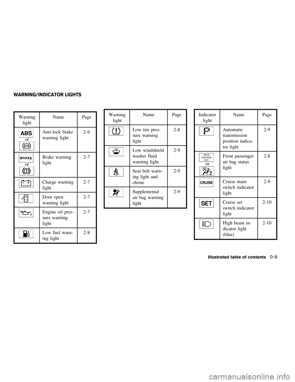
Warning
lightName Page
or
Anti-lock brake
warning light2-6
or
Brake warning
light2-7
Charge warning
light2-7
Door open
warning light2-7
Engine oil pres-
sure warning
light2-7
Low fuel warn-
ing light2-8
Warning
lightName Page
Low tire pres-
sure warning
light2-8
Low windshield
washer fluid
warning light2-9
Seat belt warn-
ing light and
chime2-9
Supplemental
air bag warning
light2-9
Indicator
lightName Page
Automatic
transmission
position indica-
tor light2-9
or
Front passenger
air bag status
light2-8
Cruise main
switch indicator
light2-9
Cruise set
switch indicator
light2-10
High beam in-
dicator light
(blue)2-10
WARNING/INDICATOR LIGHTS
Illustrated table of contents0-9
ZREVIEW COPY:Ð2004 Quest(van)
Owners Manual(owners)ÐUSA English(nna)
10/08/03Ðtbrooks
X
Page 82 of 320

orAnti-lock brake warning lightSeat belt warning light and chimeorFront passenger air bag status
light
orBrake warning lightSupplemental air bag warning lightSecurity indicator light (NVIS)
Charge warning lightAutomatic transmission position indicator lightSlip indicator light
Door open warning lightCruise main switch indicator lightTraction control system off indicator light (if so
equipped)
Engine oil pressure warning lightCruise set switch indicator lightTurn signal/hazard indicator lights
Low fuel warning lightHigh beam indicator light (Blue)Vehicle dynamic control off indicator light (if so
equipped)
Low tire pressure warning lightMalfunction indicator lamp (MIL)
Low windshield washer fluid warning lightOverdrive off indicator light
CHECKING BULBS
With all doors closed, apply the parking brake
and turn the ignition key to the ON position
without starting the engine. The following lights
will come on:
,or,,,
The following lights come on briefly and then go
off:
or,,,,,,
If any light fails to come on, it may indicate
a burned-out bulb or an open circuit in the
electrical system. Have the system repaired
promptly.
WARNING LIGHTS
orAnti-lock brake
warning light
If the light comes on while the engine is running,
it may indicate the anti-lock brake system is not
functioning properly. Have the system checked
by a NISSAN dealer.
WARNING/INDICATOR LIGHTS AND
AUDIBLE REMINDERS
2-6Instruments and controls
ZREVIEW COPY:Ð2004 Quest(van)
Owners Manual(owners)ÐUSA English(nna)
10/08/03Ðtbrooks
X
Page 83 of 320

Turn off the engine, and start it again by
slowly turning the ignition key (quickly do-
ing so may cause the ABS light to stay on
when there is nothing wrong) . If the light
stays on, have the system checked by a
NISSAN dealer.
If an abnormality occurs in the system, the anti-
lock function ceases, but the regular braking
system continues to operate.
If the light comes on while you are driving,
contact a NISSAN dealer for repair.
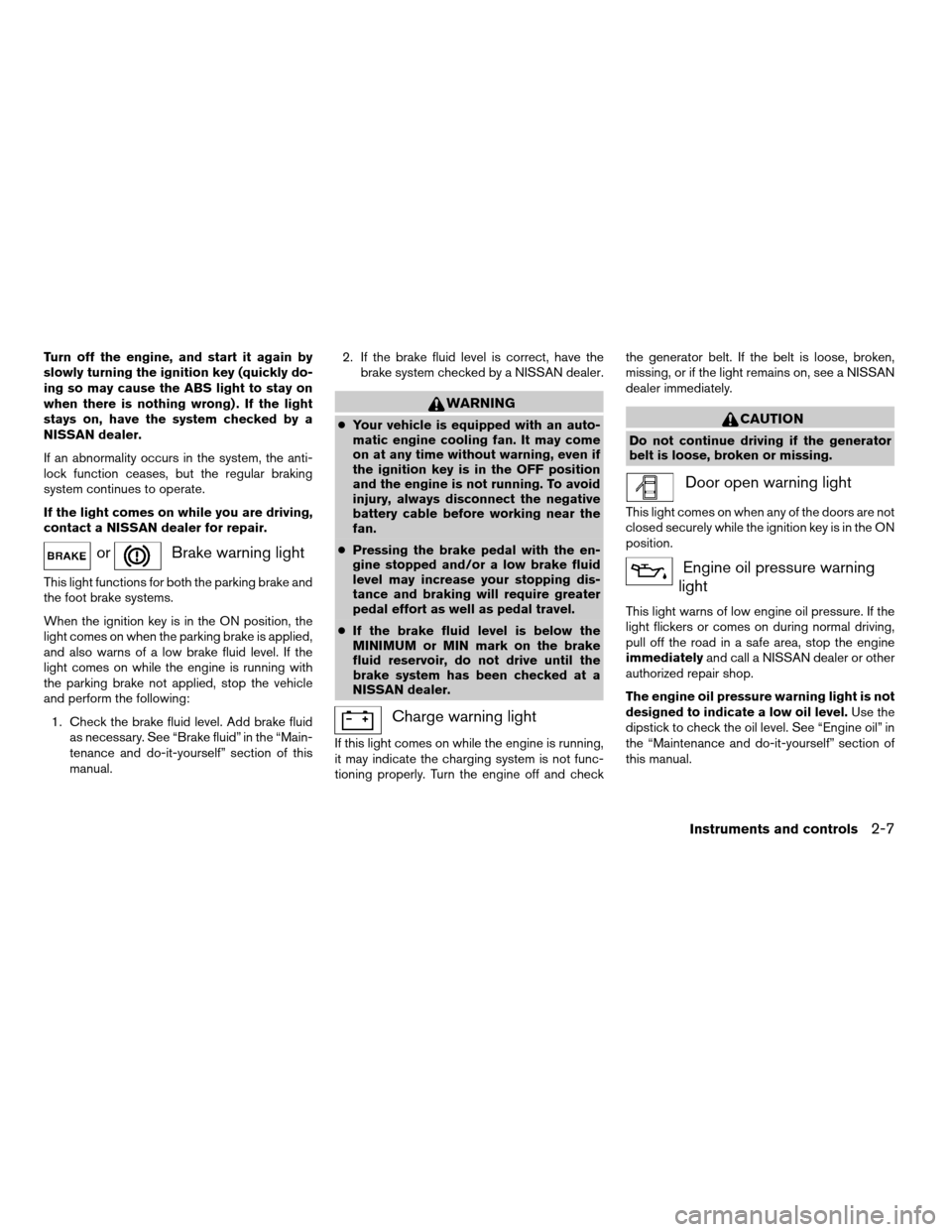
orBrake warning light
This light functions for both the parking brake and
the foot brake systems.
When the ignition key is in the ON position, the
light comes on when the parking brake is applied,
and also warns of a low brake fluid level. If the
light comes on while the engine is running with
the parking brake not applied, stop the vehicle
and perform the following:
1. Check the brake fluid level. Add brake fluid
as necessary. See “Brake fluid” in the “Main-
tenance and do-it-yourself” section of this
manual.2. If the brake fluid level is correct, have the
brake system checked by a NISSAN dealer.
WARNING
cYour vehicle is equipped with an auto-
matic engine cooling fan. It may come
on at any time without warning, even if
the ignition key is in the OFF position
and the engine is not running. To avoid
injury, always disconnect the negative
battery cable before working near the
fan.
cPressing the brake pedal with the en-
gine stopped and/or a low brake fluid
level may increase your stopping dis-
tance and braking will require greater
pedal effort as well as pedal travel.
cIf the brake fluid level is below the
MINIMUM or MIN mark on the brake
fluid reservoir, do not drive until the
brake system has been checked at a
NISSAN dealer.
Charge warning light
If this light comes on while the engine is running,
it may indicate the charging system is not func-
tioning properly. Turn the engine off and checkthe generator belt. If the belt is loose, broken,
missing, or if the light remains on, see a NISSAN
dealer immediately.
CAUTION
Do not continue driving if the generator
belt is loose, broken or missing.
Door open warning light
This light comes on when any of the doors are not
closed securely while the ignition key is in the ON
position.
Engine oil pressure warning
light
This light warns of low engine oil pressure. If the
light flickers or comes on during normal driving,
pull off the road in a safe area, stop the engine
immediatelyand call a NISSAN dealer or other
authorized repair shop.
The engine oil pressure warning light is not
designed to indicate a low oil level.Use the
dipstick to check the oil level. See “Engine oil” in
the “Maintenance and do-it-yourself” section of
this manual.
Instruments and controls2-7
ZREVIEW COPY:Ð2004 Quest(van)
Owners Manual(owners)ÐUSA English(nna)
10/08/03Ðtbrooks
X
Page 88 of 320

While the vehicle dynamic control system is op-
erating, you might feel slight vibration or hear the
system working when starting the vehicle or ac-
celerating, but this is normal.
AUDIBLE REMINDERS
Brake pad wear warning
The front disc brake pads have audible wear
warnings. When a front brake pad requires re-
placement, it makes a high pitched scraping
sound when the vehicle is in motion, whether or
not the brake pedal is depressed. Have the
brakes checked as soon as possible if the warn-
ing sound is heard.
Key reminder chime
A chime sounds if the driver’s door is opened
while the key is left in the ignition switch. Remove
the key and take it with you when leaving the
vehicle.
Light reminder chime
With the ignition switch in the OFF position, a
chime sounds when the driver’s door is opened if
the headlights or parking lights are on.
Turn the headlight control switch off before leav-
ing the vehicle.
NISSAN VEHICLE IMMOBILIZER
SYSTEM (NVIS)
The NISSAN Vehicle Immobilizer System (NVIS)
will not allow the engine to start without the use of
a registered NVIS key.
If the engine fails to start using a registered NVIS
key (for example, when interference is caused by
another NVIS key, an automated toll road device
or automatic payment device on the key ring) ,
restart the engine using the following proce-
dures:
1. Leave the ignition switch in the ON position
for approximately 5 seconds.
2. Turn the ignition switch to the OFF or LOCK
position, and wait approximately 5 seconds.
3. Repeat steps 1 and 2.
4. Restart the engine while holding the device
(which may have caused the interference)
separate from the registered NVIS key.
If the no start condition re-occurs, NISSAN rec-
ommends placing the registered NVIS key on a
separate key ring to avoid interference from other
devices.Statement related to Section 15 of FCC
Rules for NISSAN Vehicle Immobilizer Sys-
tem (CONT ASSY — IMMOBILIZER, ANT
ASSY — IMMOBILIZER)
This device complies with part 15 of the
FCC Rules and RSS-210 of Industry
Canada. Operation is subject to the follow-
ing two conditions;
(1) This device may not cause harmful in-
terference, and (2) this device must accept
any interference received, including inter-
ference that may cause undesired opera-
tion of the device.
CHANGES OR MODIFICATIONS NOT EX-
PRESSLY APPROVED BY THE MANUFAC-
TURER FOR COMPLIANCE COULD VOID
THE USER’S AUTHORITY TO OPERATE
THE EQUIPMENT.
SECURITY SYSTEM
2-12Instruments and controls
ZREVIEW COPY:Ð2004 Quest(van)
Owners Manual(owners)ÐUSA English(nna)
10/08/03Ðtbrooks
X
Page 94 of 320

After the headlights automatically turn off with the
headlight switch in theorposition,
the headlights will illuminate again for 5 minutes if
the headlight switch is moved to the OFF position
and then turned to the
orposition.
CAUTION
cBe sure to turn the light switch to the
OFF position when you leave the ve-
hicle for extended periods of time, oth-
erwise the battery will go dead.
cNever leave the light switch on when
the engine is not running for extended
periods of time even if the headlights
turn off automatically.
DAYTIME RUNNING LIGHT SYSTEM
(Canada only)
The headlights automatically illuminate at a re-
duced intensity when the engine is started with
the parking brake released. The daytime running
lights operate with the headlight switch in the
OFF position or in the
position. Turn the
headlight switch to theposition for full
illumination when driving at night.
If the parking brake is applied before the engine is
started, the daytime running lights do not illumi-
nate. The daytime running lights illuminate whenthe parking brake is released. The daytime run-
ning lights will remain on until the ignition switch
is turned off.
WARNING
When the daytime running light system is
active, tail lights on your vehicle are not
on. It is necessary at dusk to turn on your
headlights. Failure to do so could cause
an accident injuring yourself and others.
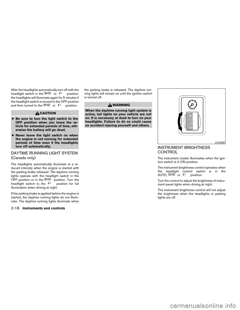
INSTRUMENT BRIGHTNESS
CONTROL
The instrument cluster illuminates when the igni-
tion switch is in ON position.
The instrument brightness control operates when
the headlight control switch is in the
AUTO,
orposition.
Turn the control to adjust the brightness of instru-
ment panel lights when driving at night.
The instrument brightness control will not adjust
the brightness when the headlights or parking
lights are off.
LIC0392
2-18Instruments and controls
ZREVIEW COPY:Ð2004 Quest(van)
Owners Manual(owners)ÐUSA English(nna)
10/08/03Ðtbrooks
X
Page 144 of 320

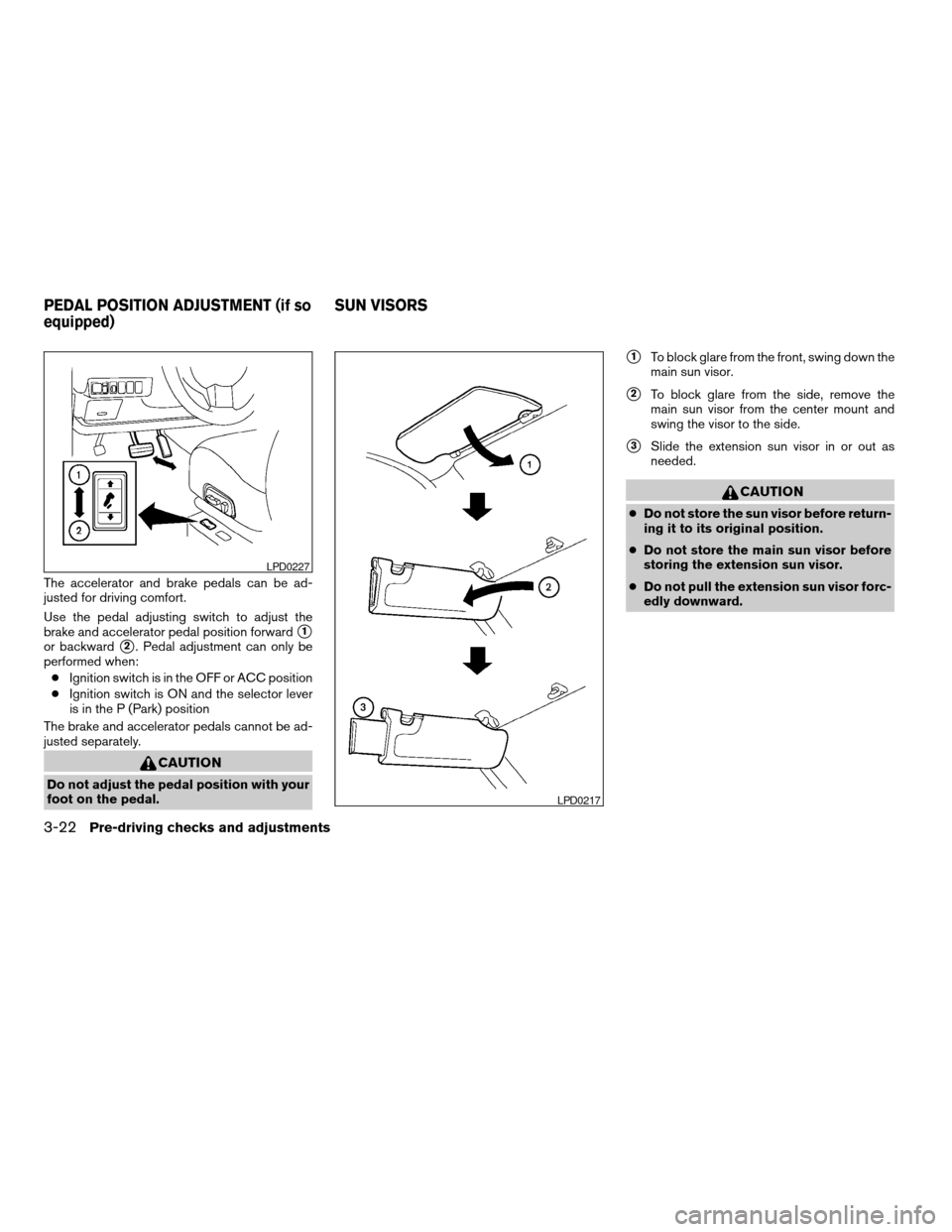
The accelerator and brake pedals can be ad-
justed for driving comfort.
Use the pedal adjusting switch to adjust the
brake and accelerator pedal position forward
s1
or backwards2. Pedal adjustment can only be
performed when:
cIgnition switch is in the OFF or ACC position
cIgnition switch is ON and the selector lever
is in the P (Park) position
The brake and accelerator pedals cannot be ad-
justed separately.
CAUTION
Do not adjust the pedal position with your
foot on the pedal.
s1To block glare from the front, swing down the
main sun visor.
s2To block glare from the side, remove the
main sun visor from the center mount and
swing the visor to the side.
s3Slide the extension sun visor in or out as
needed.
CAUTION
cDo not store the sun visor before return-
ing it to its original position.
cDo not store the main sun visor before
storing the extension sun visor.
cDo not pull the extension sun visor forc-
edly downward.
LPD0227
LPD0217
PEDAL POSITION ADJUSTMENT (if so
equipped)SUN VISORS
3-22Pre-driving checks and adjustments
ZREVIEW COPY:Ð2004 Quest(van)
Owners Manual(owners)ÐUSA English(nna)
10/08/03Ðtbrooks
X
Page 148 of 320

MEMORY STORAGE FUNCTION
Two positions for the driver’s seat, accelerator
and brake pedals, and outside mirrors can be
stored in the automatic drive positioner memory.
Follow these procedures to use the memory sys-
tem.
1. Set the automatic transmission selector le-
ver to the P (Park) position.
2. Turn the ignition ON.3. Adjust the driver’s seat, accelerator and
brake pedals, and outside mirrors to the
desired positions by manually operating
each adjusting switch. For additional infor-
mation, see “Seats” in the “Safety—Seats,
seat belts and supplemental air bags” sec-
tion and “Pedal position adjustment” and
“Outside mirrors” earlier in this section.
During this step, do not turn the ignition to
any position other than ON.
4. Push the SET switch and, within 5 seconds,
push the memory switch (1 or 2) fully for at
least 1 second.
The indicator light for the pushed memory
switch will come on and stay on for approxi-
mately 5 seconds after pushing the switch.
After the indicator light goes off, the se-
lected positions are stored in the selected
memory (1 or 2) .
If memory is stored in the same memory switch,
the previous memory will be deleted.
Linking a keyfob to a stored memory
position
A keyfob can be linked to a stored memory posi-
tion with the following procedure.
1. Follow the steps for storing a memory posi-
tion.2. While the indicator light for the memory
switch being set is illuminated for 5 sec-
onds, press the
button on the keyfob.
The indicator light will blink. After the indica-
tor light goes off, the keyfob is linked to that
memory setting.
With the key removed from the ignition switch,
press the
button on the keyfob. The driv-
er’s seat and outside mirrors will move to the
memorized position.
Procedure for storing the outside mir-
ror positions for best visibility when
backing up
Two outside mirror positions for backing up can
be stored in the automatic drive positioner
memory.
1. Set the parking brake.
2. Turn the ignition ON. (Do not start the en-
gine.)
3. Push the memory switch 1 or 2 fully for at
least 1 second to operate the automatic
drive positioner.
4. Turn the outside mirror control switch to L
(left) .
5. Depress the brake pedal.
LPD0219
3-26Pre-driving checks and adjustments
ZREVIEW COPY:Ð2004 Quest(van)
Owners Manual(owners)ÐUSA English(nna)
10/08/03Ðtbrooks
X
Page 149 of 320

6. Move the automatic transmission shift lever
to R (Reverse) .
7. Adjust the mirror to the desired viewing po-
sition for backing up by operating the out-
side mirror control switch.
8. Push the SET switch and, within 5 seconds,
push the memory switch 1 or 2 selected in
step 3 fully for at least 1 second.
cThe indicator light for the pushed memory
switch will come on and stay on for approxi-
mately 5 seconds after pushing the switch.
After the indicator light goes off, the se-
lected mirror position is stored in the se-
lected memory (1 or 2) .
9. Turn the outside mirror control switch to R
(right) . Repeat the above procedure to ad-
just the right mirror position and store in the
selected memory.
cWhen the driver’s seat, outside mirror and
steering column are not in the memorized
position, the outside mirror will move with
the initial tilt-down angle.
Confirming memory storage
cTurn the ignition ON and push the SET
switch. If the main memory has not been
stored, the indicator light will come on for
approximately 0.5 seconds. When thememory has stored the position, the indica-
tor light will stay on for approximately 5 sec-
onds.
cIf the battery cable is disconnected, or if the
fuse blows, the memory will be canceled. In
such a case, reset the desired positions
using the following procedures.
1. Open and close the driver’s door more than
two times with the ignition key in the LOCK
position.
2. Reset the desired position using the previ-
ous procedure.
Selecting the memorized position
1. Set the automatic transmission selector le-
ver to the P (Park) position.
2. Turn the ignition ON.
3. Push the memory switch (1 or 2) fully for at
least 1 second.
The driver’s seat, accelerator and brake
pedals, and outside mirrors will move to the
memorized position with the indicator light
blinking, and then the light will stay on for
approximately 5 seconds.
ENTRY/EXIT FUNCTION
This system is designed so that the driver’s seat
will automatically move when the automatic
transmission selector lever is in the P (Park)
position. This allows the driver to get into and out
of the driver’s seat more easily.
The driver’s seat will slide backward:
cWhen the key is removed from the ignition
switch.
cWhen the driver’s door is opened with the
key turned to LOCK.
cWhen the key is turned from ACC to LOCK
with the driver’s door open while the auto-
matic transmission selector lever is in the P
(Park) position.
The driver’s seat will return to previous position:
cWhen the key is inserted into the ignition
switch.
cWhen the driver’s door is closed with the key
turned to LOCK.
cWhen the key is turned from ACC to ON
while the automatic transmission selector
lever is in the P (Park) position.
The entry/exit function can be adjusted or can-
celed. See “Personalized settings menu” (ve-
hicles without navigation system) or “Vehicle
Pre-driving checks and adjustments3-27
ZREVIEW COPY:Ð2004 Quest(van)
Owners Manual(owners)ÐUSA English(nna)
10/08/03Ðtbrooks
X
Page 207 of 320

5 Starting and driving
Precautions when starting and driving................5-2
Exhaust gas (carbon monoxide)..................5-2
Three-way catalyst..............................5-2
Low tire pressure warning system................5-3
Avoiding collision and rollover....................5-4
Drinking alcohol/drugs and driving................5-5
Ignition switch.....................................5-5
Automatic transmission..........................5-5
Key positions..................................5-6
Nissan vehicle immobilizer system (NVIS).........5-6
Before starting the engine..........................5-6
Starting the engine................................5-7
Driving the vehicle.................................5-7
Automatic transmission..........................5-7
Parking brake....................................5-11
Cruise control....................................5-12
Precautions on cruise control...................5-12
Cruise control operations.......................5-12
Break-in schedule................................5-13Increasing fuel economy...........................5-14
Parking/parking on hills............................5-15
Power steering...................................5-15
Brake system....................................5-16
Brake precautions.............................5-16
Anti-lock brake system (ABS)...................5-16
Traction control system (TCS)......................5-18
Vehicle dynamic control (VDC) system
(if so equipped)..................................5-19
Rear sonar system (if so equipped).................5-20
Cold weather driving..............................5-21
Freeing a frozen door lock......................5-21
Anti-freeze....................................5-21
Battery.......................................5-21
Draining of coolant water.......................5-21
Tire equipment................................5-21
Special winter equipment.......................5-22
Driving on snow or ice.........................5-22
ZREVIEW COPY:Ð2004 Quest(van)
Owners Manual(owners)ÐUSA English(nna)
10/08/03Ðtbrooks
X