warning lights NISSAN QUEST 2005 V42 / 3.G Owner's Manual
[x] Cancel search | Manufacturer: NISSAN, Model Year: 2005, Model line: QUEST, Model: NISSAN QUEST 2005 V42 / 3.GPages: 328, PDF Size: 5.75 MB
Page 218 of 328
WARNING
Never remove or turn the key to the LOCK
position while driving. The steering wheel
will lock. This may cause the driver to lose
control of the vehicle and could result in
serious vehicle damage or personal injury.
KEY POSITIONS
LOCK: Normal parking position (0)
OFF: (Not used) (1)
ACC: (Accessories) (2)
This position activates electrical accessories
such as the radio when the engine is not running.
ON: Normal operating position (3)
This position turns on the ignition system and the
electrical accessories.
START: (4)
This position starts the engine. As soon as the
engine has started, release the key. It automati-
cally returns to the ON position.
NISSAN VEHICLE IMMOBILIZER
SYSTEM (NVIS)
The NISSAN Vehicle Immobilizer System (NVIS)
will not allow the engine to start without the use of
the registered NVIS key.
If the engine fails to start using the registered
NVIS key, it may be due to interference caused by
another NVIS key, an automated toll road device
or automated payment device on the key ring.
Restart the engine using the following proce-
dures:
1. Leave the ignition switch in the ON position
for approximately 5 seconds.
2. Turn the ignition switch to the OFF or LOCK
position and wait approximately 10 seconds.
3. Repeat step 1 and 2 again.
4. Restart the engine while holding the device
(which may have caused the interference)
separate from the registered NVIS key.
If this procedure allows the engine to start,
NISSAN recommends placing the registered
NVIS key on a separate key ring to avoid interfer-
ence from other devices.cMake sure the area around the vehicle is
clear.
cCheck fluid levels such as engine oil, cool-
ant, brake fluid, and window washer fluid as
frequently as possible, or at least whenever
you refuel.
cCheck that all windows and lights are clean.
cVisually inspect tires for their appearance
and condition. Also check tires for proper
inflation.
cLock all doors.
cPosition seat and adjust head restraints.
cAdjust inside and outside mirrors.
cFasten seat belts and ask all passengers to
do likewise.
cCheck the operation of warning lights when
the key is turned to the ON (3) position. See
“Warning/indicator lights and audible re-
minders” in the “Instruments and controls”
section of this manual.
BEFORE STARTING THE ENGINE
5-6Starting and driving
ZREVIEW COPYÐ2005 Quest(van)
Owners ManualÐUSA_English(nna)
07/21/04Ðdebbie
X
Page 222 of 328
To push the shift lock release, complete the fol-
lowing procedure:
1. Turn the ignition key to the LOCK position
and remove the key
2. Apply the parking brake.
3. Remove the shift lock release cover as
shown.
4. Insert a small screwdriver in the shift lock
release slot and push down.
5. Move the shift selector lever to the N (Neu-
tral) position while holding down the shift
lock release.
6. Turn the key to the ON position to unlock the
steering wheel. Now the vehicle may be
moved to the desired location.
If the shift selector lever cannot be moved out of
P (Park) , have a NISSAN dealer check the auto-
matic transmission system as soon as possible.
WARNING
If the selector lever cannot be moved from
the P (Park) position while the engine is
running and the brake pedal is depressed,
the stop lights may not work. Malfunction-
ing stop lights could cause an accident
injuring yourself and others.
Accelerator downshift
— in D position —
For passing or hill climbing, depress the accel-
erator pedal to the floor. This shifts the transmis-
sion down into a lower gear, depending on the
vehicle speed.
Fail-safe
When the fail-safe operation occurs, please note
that the 4–speed automatic transmission will be
locked in third gear. For the 5–speed automatic
transmission, the transmission will be locked in
any of the gears according to the condition.
If the vehicle is driven under extreme con-
ditions, such as excessive wheel spinning
and subsequent hard braking, the fail-safe
system may be activated. This will occur
even if all electrical circuits are functioning
properly. In this case, turn the ignition key
OFF and wait for 3 seconds. Then turn the
key back to the ON position. The vehicle
should return to its normal operating con-
dition. If it does not return to its normal
operating condition, have a NISSAN dealer
check the transmission and repair it if nec-
essary.
Overdrive switch
Each time your vehicle is started, the transmis-
sion is automatically “reset” to overdrive ON.
ON: With the engine running and the
shift selector lever in the D (Drive)
position, the transmission upshifts
into Overdrive as vehicle speed
increases.
Overdrive does not engage until the engine
has reached operating temperature.
WSD0084
5-10Starting and driving
ZREVIEW COPYÐ2005 Quest(van)
Owners ManualÐUSA_English(nna)
07/21/04Ðdebbie
X
Page 230 of 328
When accelerating on slippery surfaces the tire
may spin or slip. With the vehicle traction control
system (TCS) , sensors detect these movements
and control the braking and engine output to help
improve vehicle stability while accelerating.
cWhen the traction control system is operat-
ing, the slip indicator in the instrument panel
blinks.
cIf the slip indicator blinks, the vehicle is un-
der slippery conditions. Be sure to drive
carefully. See “Slip indicator light” and “Trac-
tion control system (TCS) off indicator light”
in the “Instruments and controls” section of
this manual.
cIf a malfunction occurs in the system,
the
andindicator lights
come on in the meter panel.
As long as these lights are on, the traction control
function is canceled. The vehicle will behave like
a vehicle without the system.
WARNING
cThe traction control system is designed
to help improve driving stability but
does not prevent accidents due to
abrupt steering operation at high
speeds or by careless or dangerous
driving techniques. Reduce vehicle
speed and be especially careful when
driving and cornering on slippery sur-
faces and always drive carefully.
cIf brake related parts such as brake
pads, rotors and calipers are not stan-
dard equipment or are extremely dete-
riorated, the traction control system
may not operate properly and the
indicator light may come on.
cDo not modify the vehicle’s suspension.
If suspension parts such as shock ab-
sorbers, struts, springs and bushings
are not standard equipment or are ex-
tremely deteriorated, the traction con-
trol system may not operate properly
and the
indicator light may come
on.cWhen driving on extremely inclined sur-
faces such as higher banked corners,
the traction control system may not op-
erate properly and the
indicator
light may come on. Do not drive on
these types of roads.
cIf wheels or tires other than the recom-
mended ones are used, the traction
control system may not operate prop-
erly and the
indicator light may
come on.
cThe traction control system is not a sub-
stitute for winter tires or tire chains on a
snow covered road.
TRACTION CONTROL SYSTEM (TCS)
5-18Starting and driving
ZREVIEW COPYÐ2005 Quest(van)
Owners ManualÐUSA_English(nna)
07/21/04Ðdebbie
X
Page 231 of 328
When accelerating or driving on slippery sur-
faces, the tires may spin or slide. With the Vehicle
Dynamic Control (VDC) system, sensors detect
these movements and control the braking and
engine output to help improve vehicle stability.
cWhen the vehicle dynamic control (VDC)
system is operating, the slip indicator in the
instrument panel blinks.
cWhen only the traction control system (TCS)
portion of the vehicle dynamic control sys-
tem is operating, the slip indicator will also
blink.
cIf the slip indicator blinks, the road condi-
tions are slippery. Be sure to adjust your
speed and driving to these conditions. See
“Slip indicator light”, and “Vehicle dynamic
control (VDC) off indicator light” in the “In-
struments and controls” section.
cIndicator light
If malfunction occurs in the system,
the
andindicator lights come
on in the instrument panel.
As long as these indicator lights are on, the
traction control function is canceled.
The VDC system uses an Active Brake Limited
Slip (ABLS) system to improve vehicle traction.
The ABLS system works when one of the driving
wheels is spinning on a slippery surface. TheABLS system brakes the spinning wheel which
distributes the driving power to the other drive
wheel. If the vehicle is operated with the vehicle
dynamic control system off using the VDC OFF
switch, all VDC and ABLS functions will be
turned off. The ABS will still operate with the VDC
system off. When the ABLS system is activated,
the slip indicator light will blink and you may hear
a clunk noise and/or feel a pulsation in the brake
pedal. This is normal.
While the VDC system is operating, you may feel
a pulsation in the brake pedal and hear a noise or
vibration from under the hood. This is normal and
indicates that the VDC system is working prop-
erly.
The computer has a built in diagnostic feature
that tests the system each time you start the
engine and move the vehicle forward or in reverse
at a slow speed. When the self-test occurs, you
may hear a clunk noise and/or feel a pulsation in
the brake pedal. This is normal and is not an
indication of a malfunction.
WARNING
cThe vehicle dynamic control system is
designed to help improve driving stabil-
ity but does not prevent accidents due
to abrupt steering operation at high
speeds or by careless or dangerous
driving techniques. Reduce vehicle
speed and be especially careful when
driving and cornering on slippery sur-
faces and always drive carefully.
cIf brake related parts such as brake
pads, rotors and calipers are not stan-
dard equipment or are extremely dete-
riorated, the vehicle dynamic control
system may not operate properly and
the vehicle dynamic control off indica-
tor light may come on.
cDo not modify the vehicle’s suspension.
If suspension parts such as shock ab-
sorbers, struts, springs, stabilizer bars
and bushings are not NISSAN approved
for your vehicle or are extremely dete-
riorated the vehicle dynamic control
system may not operate properly. This
could adversely affect vehicle handling
performance, and the vehicle dynamic
control off indicator light may come on.
VEHICLE DYNAMIC CONTROL (VDC)
SYSTEM (if so equipped)
Starting and driving5-19
ZREVIEW COPYÐ2005 Quest(van)
Owners ManualÐUSA_English(nna)
07/21/04Ðdebbie
X
Page 236 of 328
LOW TIRE PRESSURE WARNING
SYSTEM
This vehicle is equipped with the low tire pres-
sure warning system. It monitors tire pressure of
all tires except the spare. When the low tire
pressure warning light is lit, one or more of your
tires is significantly under-inflated. If equipped,
the system also displays pressure of all tires
(except the spare tire) on the display screen by
sending a signal from a sensor that is installed in
each wheel. If the vehicle is being driven with low
tire pressure (lower than 28 psi, 193 kPa) , the
low tire pressure warning system will activate and
warn you of it by the low tire pressure warning
light. This system will activate only when the
vehicle is driven at speeds above 20 MPH (32
km/h) . For more details, refer to
“Warning/indicator lights and audible reminders”
in the “Instruments and controls” section, “Tire
pressure information” in the “Display screen,
heater, air conditioner and audio systems” sec-
tion and “Low tire pressure warning system” in
the “Starting and driving” section.
WARNING
cIf the low tire pressure warning light
flashes while driving, avoid sudden
steering maneuvers or abrupt braking,
reduce vehicle speed, pull off the road
to a safe location and stop the vehicle
as soon as possible. Serious vehicle
damage could occur and may lead to an
accident and could result in serious
personal injury. Check the tire pressure
for all four tires. Adjust the tire pressure
to the recommended COLD tire pres-
sure shown on the Tire and Loading
Information label to turn the low tire
pressure warning light OFF. If you have
a flat tire, replace it with a spare tire as
soon as possible.
cWhen a spare tire is mounted or a wheel
is replaced, tire pressure will not be
indicated and the low tire pressure
warning system will not function. Con-
tact your NISSAN dealer as soon as
possible for tire replacement and/or
system resetting.
cDo not inject any tire liquid or aerosol
tire sealant into the tires, as this may
cause a malfunction of the tire pressure
sensors.
CHANGING A FLAT TIRE
If you have a flat tire, follow the instructions be-
low.
Stopping the vehicle
1. Safely move the vehicle off the road and
away from traffic.
2. Turn on the hazard warning flashers.
3. Park on a level surface and apply the parking
brake. Shift the transmission into P (Park) .
4. Turn off the engine.
5. Raise the hood to warn other traffic and to
signal professional road assistance person-
nel that you need assistance.
6. Have all passengers get out of the vehicle
and stand in a safe place, away from traffic
and clear of the vehicle.
WARNING
cMake sure the parking brake is securely
applied and the automatic transmission
is shifted into P (Park) .
cNever change tires when the vehicle is
on a slope, ice or slippery areas. This is
hazardous.
FLAT TIRE
6-2In case of emergency
ZREVIEW COPYÐ2005 Quest(van)
Owners ManualÐUSA_English(nna)
07/21/04Ðdebbie
X
Page 242 of 328
WARNING
Always follow the instructions below.
Failure to do so could result in damage to
the charging system and cause personal
injury.
1. If the booster battery is in another vehicle,
position the two vehicles to bring their bat-
teries near each other.
Do not allow the two vehicles to touch.
2. Apply the parking brake. Shift the transmis-
sion into P (Park) . Switch off all unnecessary
electrical systems (lights, heater, air condi-
tioner, etc.) .3. Remove vent caps on the battery (if so
equipped) . Cover the battery with an old
cloth to reduce explosion hazard.
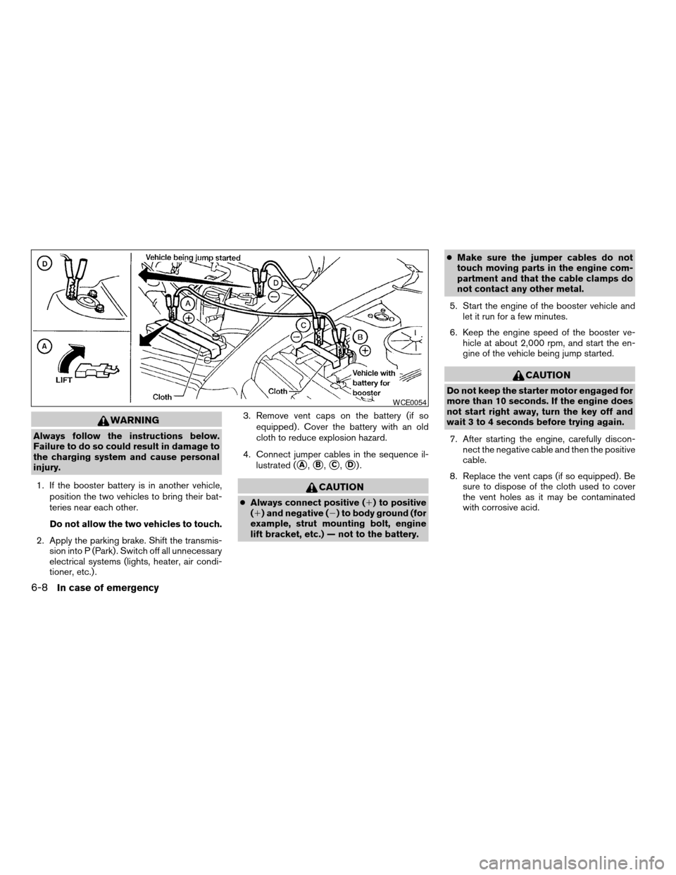
4. Connect jumper cables in the sequence il-
lustrated (
sA,sB,sC,sD).
CAUTION
cAlways connect positive (1) to positive
(1) and negative (2) to body ground (for
example, strut mounting bolt, engine
lift bracket, etc.) — not to the battery.cMake sure the jumper cables do not
touch moving parts in the engine com-
partment and that the cable clamps do
not contact any other metal.
5. Start the engine of the booster vehicle and
let it run for a few minutes.
6. Keep the engine speed of the booster ve-
hicle at about 2,000 rpm, and start the en-
gine of the vehicle being jump started.
CAUTION
Do not keep the starter motor engaged for
more than 10 seconds. If the engine does
not start right away, turn the key off and
wait 3 to 4 seconds before trying again.
7. After starting the engine, carefully discon-
nect the negative cable and then the positive
cable.
8. Replace the vent caps (if so equipped) . Be
sure to dispose of the cloth used to cover
the vent holes as it may be contaminated
with corrosive acid.
WCE0054
6-8In case of emergency
ZREVIEW COPYÐ2005 Quest(van)
Owners ManualÐUSA_English(nna)
07/21/04Ðdebbie
X
Page 255 of 328

When driving in areas using road salt or other
corrosive materials, check lubrication frequently.
Lights*Clean the headlights on a regular basis.
Make sure that the headlights, stop lights, tail
lights, turn signal lights, and other lights are all
operating properly and installed securely. Also
check headlight aim.
Road wheel nuts*When checking the tires,
make sure no wheel nuts are missing, and check
for any loose wheel nuts. Tighten if necessary.
Tire rotation*Tires should be rotated every
7,500 miles (12,000 km) .
Tires*Check the pressure with a gauge often
and always prior to long distance trips. If neces-
sary, adjust the pressure in all tires, including the
spare, to the pressure specified. Check carefully
for damage, cuts or excessive wear.
Wheel alignment and balanceIf the vehicle
should pull to either side while driving on a
straight and level road, or if you detect uneven or
abnormal tire wear, there may be a need for wheel
alignment. If the steering wheel or seat vibrates at
normal highway speeds, wheel balancing may be
needed.
cFor additional information regarding tires,
refer to “Important Tire Safety Information”
(US) or “Tire Safety Information” (Canada) in
the Warranty Information Booklet .WindshieldClean the windshield on a regular
basis. Check the windshield at least every six
months for cracks or other damage. Have a dam-
aged windshield repaired by a qualified repair
facility.
Windshield wiper blades*Check for cracks or
wear if they do not wipe properly.
Inside the vehicle
The maintenance items listed here should be
checked on a regular basis, such as when per-
forming periodic maintenance, cleaning the ve-
hicle, etc.
Additional information on the following
items with an “*” is found later in this sec-
tion.
Accelerator pedalCheck the pedal for smooth
operation and make sure the pedal does not bind
or require uneven effort. Keep the floor mat away
from the pedal.
Automatic transmission P (Park) position
mechanismOn a fairly steep hill check that your
vehicle is held securely with the selector lever in
the P (Park) position without applying any brakes.
Brake pedal and booster*Check the pedal for
smooth operation and make sure it has the proper
distance under it when depressed fully. Checkthe brake booster function. Be certain to keep the
floor mat away from the pedal.
BrakesCheck that the brakes do not pull the
vehicle to one side when applied.
Parking brake*Check that the lever has the
proper travel and confirm that your vehicle is held
securely on a fairly steep hill with only the parking
brake applied.
SeatsCheck seat position controls such as seat
adjusters, seatback recliner, etc. to ensure they
operate smoothly and all latches lock securely in
every position. Check that the head restraints
move up and down smoothly and the locks (if so
equipped) hold securely in all latched positions.
Seat beltsCheck that all parts of the seat belt
system (for example, buckles, anchors, adjusters
and retractors) operate properly and smoothly,
and are installed securely. Check the belt web-
bing for cuts, fraying, wear or damage.
Steering wheelCheck for changes in the steer-
ing system, such as excessive freeplay, hard
steering or strange noises.
Warning lights and chimesMake sure all
warning lights and chimes are operating properly.
Windshield wiper and washer*Check that
the wipers and washer operate properly and that
the wipers do not streak.
Maintenance and do-it-yourself8-3
ZREVIEW COPYÐ2005 Quest(van)
Owners ManualÐUSA_English(nna)
07/21/04Ðdebbie
X
Page 309 of 328
Trailer lights should comply with federal and/or
local regulations. For assistance in hooking up
trailer lights, contact a NISSAN dealer or repu-
table trailer dealer. A genuine NISSAN trailer tow
harness is available from your NISSAN dealer.
Trailer brakes
If your trailer is equipped with a braking system,
make sure it conforms to federal and/or local
regulations and that it is properly installed.
WARNING
Never connect a trailer brake system di-
rectly to the vehicle brake system.
Pre-towing tips
cBe certain your vehicle maintains a level
position when a loaded and/or unloaded
trailer is hitched. Do not drive the vehicle if it
has an abnormal nose-up or nose-down
condition; check for improper tongue load,
overload, worn suspension or other possible
causes of either condition.
cAlways secure items in the trailer to prevent
load shift while driving.
cLoad the trailer so approximately 60% of the
trailer load is in the front half and 40% is in
the back half.cCheck your hitch, trailer tire pressure, ve-
hicle tire pressure, trailer light operation, and
trailer wheel lug nuts every time you attach a
trailer to the vehicle.
cBe certain your rearview mirrors conform to
all federal, state or local regulations. If not,
install any mirrors required for towing before
driving the vehicle.
Trailer towing tips
In order to gain skill and an understanding of the
vehicle’s behavior, you should practice turning,
stopping and backing up in an area which is free
from traffic. Steering stability and braking perfor-
mance will be somewhat different than under
normal driving conditions.
cAlways secure items in the trailer to prevent
load shift while driving.
cAvoid abrupt starts, acceleration or stops.
cAvoid sharp turns or lane changes.
cAlways drive your vehicle at a moderate
speed. Some states or provinces have spe-
cific speed limits for vehicles that are towing
trailers. Obey the local speed limits.
cWhen backing up, hold the bottom of the
steering wheel with one hand. Move your
hand in the direction in which you want the
trailer to go. Make small corrections andback up slowly. If possible, have someone
guide you when you are backing up.
cAlways block the wheels on both vehicle and
trailer when parking. Parking on a slope is
not recommended; however, if you must do
so, and if your vehicle is equipped with an
automatic transmission, first block the
wheels and apply the parking brake, and
then move the transmission shift selector
lever into the P (Park) position. If you move
the shift selector lever to the P (Park) posi-
tion before blocking the wheels and applying
the parking brake, transmission damage
could occur.
cWhen going down a hill, shift into a lower
gear and use the engine braking effect.
When going up a long grade, downshift the
transmission to a lower gear and reduce
speed to reduce chances of engine over-
loading and/or overheating.
cIf the engine coolant rises to an extremely
high temperature when the air conditioner
system is on, turn off the air conditioner.
Coolant heat can be additionally vented by
opening the windows, switching the fan
control to high and setting the temperature
control to the HOT position.
cTrailer towing requires more fuel than normal
circumstances.
Technical and consumer information9-17
ZREVIEW COPYÐ2005 Quest(van)
Owners ManualÐUSA_English(nna)
07/22/04Ðdebbie
X
Page 319 of 328

Floor mat positioning aid.............7-4
Fluid
Automatic transmission fluid (ATF). . . .8-11
Brake fluid..................8-13
Capacities and recommended
fuel/lubricants.................9-2
Engine coolant................8-7
Engine oil...................8-8
Power steering fluid.............8-13
Window washer fluid............8-14
F.M.V.S.S. certification label..........9-10
Fog light switch.................2-22
Front air bag system
(See supplemental restraint system).....1-55
Front seats....................1-2
Fuel
Capacities and recommended
fuel/lubricants.................9-2
Fuel economy................5-14
Fuel filler cap................3-19
Fuel filler lid.................3-19
Fuel filler lid and cap............3-18
Fuel gauge..................2-5
Fuel octane rating..............9-4
Fuel recommendation............9-3
FUEL ECON button............4-4, 4-10
Fuel Econ button
Control panel buttons.........4-4, 4-10
Fuses......................8-23
Fusible links...................8-24
G
Garage door opener, HomeLinkTUniversal
Transceiver...................2-45Garment hook..................2-36
Gascap.....................3-19
Gauge
Engine coolant temperature gauge.....2-5
Fuel gauge..................2-5
Odometer...................2-4
Speedometer.................2-4
Tachometer..................2-4
Trip odometer.................2-4
General maintenance..............8-2
Glove box....................2-30
Glove box lock.................2-30
Grocery hooks.................2-32
H
Hazard warning flasher switch.........2-22
Head restraints..................1-9
Active head restraint.............1-8
Headlight and turn signal switch........2-18
Headlights....................8-26
Headphones
(See DVD entertainment system).......4-47
Headrest storage................2-37
Heated seats..................2-23
Heater
Heater and air conditioner
controls................4-18, 4-28
Heater operation...........4-20, 4-29
Rear seat air conditioner..........4-30
HomeLinkTUniversal Transceiver.......2-45
Hood release..................3-13
Horn.......................2-23I
Ignition switch..................5-5
Immobilizer system..........2-15, 3-2, 5-6
Important vehicle information label.......9-10
In-cabin microfilter...............8-18
Increasing fuel economy............5-14
Indicator lights and audible reminders
(See warning/indicator lights and audible
reminders).....................2-7
Inside automatic anti-glare mirror.......3-22
Inside mirror...................3-22
Instrument brightness control.........2-21
Instrument panel.................2-2
Interior lights
(see Lights on demand switch)........2-43
ISOFIX child restraints.............1-36
J
Jump starting...................6-7
K
Key ........................3-2
Keyless entry system
(See remote keyless entry system).......3-9
L
Labels
Air conditioner specification label.....9-11
10-3
ZREVIEW COPYÐ2005 Quest(van)
Owners ManualÐUSA_English(nna)
08/04/04Ðtbrooks
X
Page 320 of 328

Emission control information label.....9-10
Engine serial number............9-10
F.M.V.S.S. certification label........9-10
Vehicle identification number (VIN) plate . .9-9
Warning labels (for SRS)..........1-62
LATCH (Lower Anchors and Tethers for CHildren)
System......................1-36
License plate
Installing the license plate.........9-11
Light
Air bag warning light.........1-63, 2-10
Brake light (See stop light).........8-27
Bulb check/instrument panel........2-7
Bulb replacement..............8-27
Charge warning light.............2-8
Cornering light...............2-22
Fog light switch...............2-22
Headlight and turn signal switch......2-18
Headlights..................8-26
Light bulbs..................8-26
Low tire pressure warning light.......2-9
Low washer fluid warning light.......2-10
Passenger air bag and status light.....2-12
Personal lights...............2-44
Security indicator light...........2-12
Warning/indicator lights and audible
reminders...................2-7
Lights
Map lights..................2-45
Lights on demand switch............2-43
Lock
Back door release.............3-17
Child safety rear door lock..........3-9
Child safety sliding door lock........3-9Door locks..................3-3
Glove box lock...............2-30
Power door locks...............3-5
Low fuel warning light..............2-9
Low tire pressure warning light.........2-9
Low tire pressure warning system........5-3
Low washer fluid warning light.........2-10
Luggage (See vehicle loading information) . .9-12
M
Main ON/OFF switch
(for power doors).............3-6, 3-14
Maint (maintenance) button
Control panel buttons.........4-5, 4-10
Maint (Maintenance) button, control panel
display...................4-5, 4-10
Maintenance
General maintenance............8-2
Inside the vehicle...............8-3
Maintenance precautions..........8-5
Outside the vehicle..............8-2
Seat belt maintenance...........1-24
Under the hood and vehicle.........8-4
Malfunction indicator lamp (MIL)........2-11
Manual front seat adjustment..........1-2
Manual vent windows..............2-40
Map lights....................2-45
Map pocket...................2-31
Meters and gauges................2-3
Instrument brightness control.......2-21
Mirror
Automatic anti-glare inside mirror.....3-22
Inside mirror.................3-22Outside mirror control...........3-23
Outside mirrors...............3-23
Vanity mirror.................3-22
N
Nissan vehicle immobilizer system (NVIS) . .2-15,
3-2, 5-6
Note holder...................2-27
O
Octane rating (See fuel octane rating).....9-4
Odometer.....................2-4
Oil
Capacities and recommended
fuel/lubricants.................9-2
Changing engine oil.............8-9
Changing engine oil filter..........8-10
Checking engine oil level..........8-8
Engine oil...................8-8
Engine oil and oil filter recommendation . .9-5
Engine oil pressure low/engine coolant
temperature high warning light.......2-8
Engine oil viscosity..............9-5
Outside mirror control.............3-23
Outside mirrors.................3-23
Overdrive switch................5-10
Overheat
If your vehicle overheats...........6-9
Owner’s manual order form..........9-22
Owner’s manual/service manual order
information....................9-22
10-4
ZREVIEW COPYÐ2005 Quest(van)
Owners ManualÐUSA_English(nna)
08/04/04Ðtbrooks
X