wheel NISSAN QUEST 2017 RE52 / 4.G User Guide
[x] Cancel search | Manufacturer: NISSAN, Model Year: 2017, Model line: QUEST, Model: NISSAN QUEST 2017 RE52 / 4.GPages: 520, PDF Size: 2.5 MB
Page 91 of 520
2-4Instruments and controls
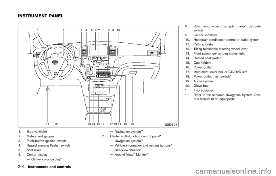
SSI0824
1. Side ventilator
2. Meters and gauges
3. Push-button ignition switch
4. Hazard warning flasher switch
5. Shift lever
6. Center display— Center color display* — Navigation system**
7. Center multi-function control panel* — Navigation system**
— Vehicle information and setting buttons*
— RearView Monitor*
— Around View
ŠMonitor* 8. Rear window and outside mirror* defroster
switch
9. Center ventilator
10. Heater/air conditioner control or audio system
11. Parking brake
12. Tilting telescopic steering wheel lever
13. Front passenger air bag status light
14. Heated seat switch*
15. Cup holders
16. Power outlet
17. Instrument lower box or CD/DVD slot
18. Power outlet main switch*
19. Audio system
20. Glove box
*: if so equipped
**: Refer to the separate Navigation System Own- er’s Manual (if so equipped) .
INSTRUMENT PANEL
Page 102 of 520
shown on the Tire and Loading
Information label to turn the low
tire pressure warning light OFF. If
the light still illuminates while driv-
ing after adjusting the tire pressure,
a tire may be flat or the TPMS may
be malfunctioning. If you have a flat
tire, replace it with a spare tire as
soon as possible. If no tire is flat
and all tires are properly inflated, it
is recommended you consult a
NISSAN dealer.
. Since the spare tire is not equipped
with the TPMS, when a spare tire is
mounted or a wheel is replaced, the
TPMS will not function and the low
tire pressure warning light will flash
for approximately 1 minute. The
light will remain on after 1 minute.
Have your tires replaced and/or
TPMS system reset as soon as
possible. It is recommended you
visit a NISSAN dealer for these
services.
. Replacing tires with those not ori-
ginally specified by NISSAN could
affect the proper operation of the
TPMS.CAUTION
.The TPMS is not a substitute for the
regular tire pressure check. Be sure
to check the tire pressure regularly.
. If the vehicle is being driven at
speeds of less than 16 MPH (25
km/h) , the TPMS may not operate
correctly.
. Be sure to correctly install the
specified size of tires to the four
wheels.
Master warning light
When the ignition switch is in the ON position,
the master warning light illuminates if any of the
following are displayed on the vehicle informa-
tion display:
.No key warning
. Low fuel warning
. Low washer fluid warning
. Parking brake release warning
. Door/liftgate open warning
. Loose fuel cap warning
. Check tire pressure warning .
Extended storage fuse warning
See “Vehicle information display” (P.2-19) .
Seat belt warning light and chime
The light and chime remind you to fasten seat
belts. The light illuminates whenever the ignition
switch is pushed to the ON position, and will
remain illuminated until the driver’s seat belt is
fastened. At the same time, the chime will sound
for approximately 6 seconds unless the driver’s
seat belt is securely fastened.
The seat belt warning light for the front
passenger will illuminate if the seat belt is not
fastened when the front passenger’s seat is
occupied. For approximately 5 seconds after the
ignition switch is in the ON position, the system
does not activate the warning light for the front
passenger.
See “Seat belts” (P.1-15) for precautions on
seat belt usage.
Supplemental air bag warning light
After pushing the ignition switch to the ON
position, the supplemental air bag warning light
will illuminate. The supplemental air bag warning
light will turn off after about 7 seconds if the
supplemental front air bag and supplemental
side air bag, curtain air bag systems and/or
pretensioner seat belt are operational.
Instruments and controls2-15
Page 110 of 520
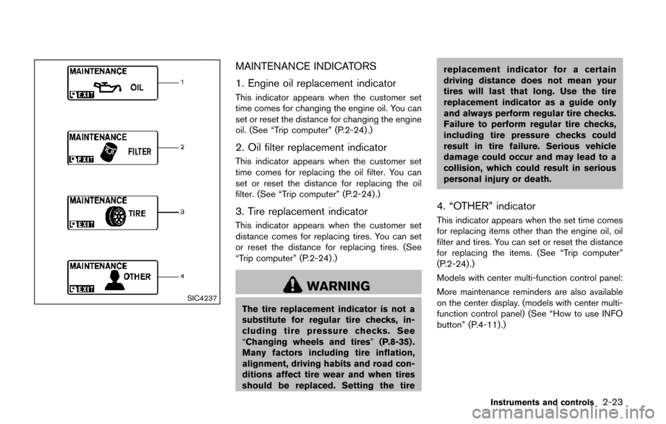
SIC4237
MAINTENANCE INDICATORS
1. Engine oil replacement indicator
This indicator appears when the customer set
time comes for changing the engine oil. You can
set or reset the distance for changing the engine
oil. (See “Trip computer” (P.2-24) .)
2. Oil filter replacement indicator
This indicator appears when the customer set
time comes for replacing the oil filter. You can
set or reset the distance for replacing the oil
filter. (See “Trip computer” (P.2-24).)
3. Tire replacement indicator
This indicator appears when the customer set
distance comes for replacing tires. You can set
or reset the distance for replacing tires. (See
“Trip computer” (P.2-24) .)
WARNING
The tire replacement indicator is not a
substitute for regular tire checks, in-
cluding tire pressure checks. See
“Changing wheels and tires”(P.8-35) .
Many factors including tire inflation,
alignment, driving habits and road con-
ditions affect tire wear and when tires
should be replaced. Setting the tire replacement indicator for a certain
driving distance does not mean your
tires will last that long. Use the tire
replacement indicator as a guide only
and always perform regular tire checks.
Failure to perform regular tire checks,
including tire pressure checks could
result in tire failure. Serious vehicle
damage could occur and may lead to a
collision, which could result in serious
personal injury or death.
4. “OTHER” indicator
This indicator appears when the set time comes
for replacing items other than the engine oil, oil
filter and tires. You can set or reset the distance
for replacing the items. (See “Trip computer”
(P.2-24) .)
Models with center multi-function control panel:
More maintenance reminders are also available
on the center display. (models with center multi-
function control panel) (See “How to use INFO
button” (P.4-11).)
Instruments and controls2-23
Page 126 of 520
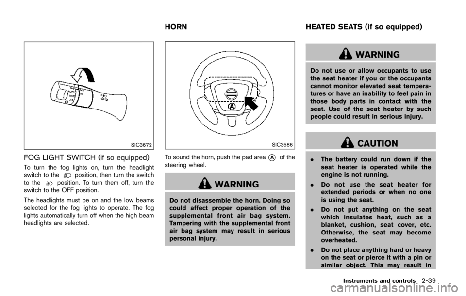
SIC3672
FOG LIGHT SWITCH (if so equipped)
To turn the fog lights on, turn the headlight
switch to theposition, then turn the switch
to theposition. To turn them off, turn the
switch to the OFF position.
The headlights must be on and the low beams
selected for the fog lights to operate. The fog
lights automatically turn off when the high beam
headlights are selected.
SIC3586
To sound the horn, push the pad area*Aof the
steering wheel.
WARNING
Do not disassemble the horn. Doing so
could affect proper operation of the
supplemental front air bag system.
Tampering with the supplemental front
air bag system may result in serious
personal injury.
WARNING
Do not use or allow occupants to use
the seat heater if you or the occupants
cannot monitor elevated seat tempera-
tures or have an inability to feel pain in
those body parts in contact with the
seat. Use of the seat heater by such
people could result in serious injury.
CAUTION
. The battery could run down if the
seat heater is operated while the
engine is not running.
. Do not use the seat heater for
extended periods or when no one
is using the seat.
. Do not put anything on the seat
which insulates heat, such as a
blanket, cushion, seat cover, etc.
Otherwise, the seat may become
overheated.
. Do not place anything hard or heavy
on the seat or pierce it with a pin or
similar object. This may result in
Instruments and controls2-39
HORN HEATED SEATS (if so equipped)
Page 128 of 520
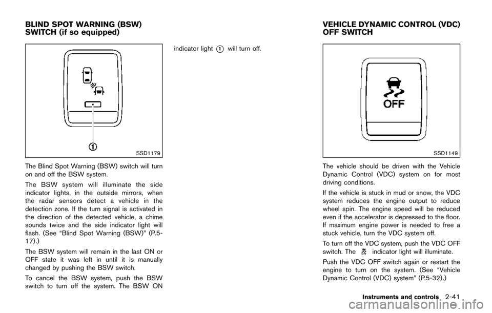
SSD1179
The Blind Spot Warning (BSW) switch will turn
on and off the BSW system.
The BSW system will illuminate the side
indicator lights, in the outside mirrors, when
the radar sensors detect a vehicle in the
detection zone. If the turn signal is activated in
the direction of the detected vehicle, a chime
sounds twice and the side indicator light will
flash. (See “Blind Spot Warning (BSW)” (P.5-
17) .)
The BSW system will remain in the last ON or
OFF state it was left in until it is manually
changed by pushing the BSW switch.
To cancel the BSW system, push the BSW
switch to turn off the system. The BSW ONindicator light
*1will turn off.
SSD1149
The vehicle should be driven with the Vehicle
Dynamic Control (VDC) system on for most
driving conditions.
If the vehicle is stuck in mud or snow, the VDC
system reduces the engine output to reduce
wheel spin. The engine speed will be reduced
even if the accelerator is depressed to the floor.
If maximum engine power is needed to free a
stuck vehicle, turn the VDC system off.
To turn off the VDC system, push the VDC OFF
switch. The
indicator light will illuminate.
Push the VDC OFF switch again or restart the
engine to turn on the system. (See “Vehicle
Dynamic Control (VDC) system” (P.5-32) .)
Instruments and controls2-41
BLIND SPOT WARNING (BSW)
SWITCH (if so equipped) VEHICLE DYNAMIC CONTROL (VDC)
OFF SWITCH
Page 183 of 520
3-32Pre-driving checks and adjustments
SPA2833
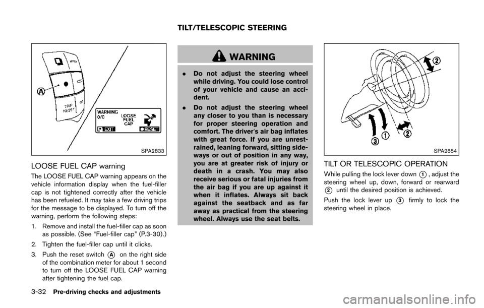
LOOSE FUEL CAP warning
The LOOSE FUEL CAP warning appears on the
vehicle information display when the fuel-filler
cap is not tightened correctly after the vehicle
has been refueled. It may take a few driving trips
for the message to be displayed. To turn off the
warning, perform the following steps:
1. Remove and install the fuel-filler cap as soonas possible. (See “Fuel-filler cap” (P.3-30) .)
2. Tighten the fuel-filler cap until it clicks.
3. Push the reset switch
*Aon the right side
of the combination meter for about 1 second
to turn off the LOOSE FUEL CAP warning
after tightening the fuel cap.
WARNING
. Do not adjust the steering wheel
while driving. You could lose control
of your vehicle and cause an acci-
dent.
. Do not adjust the steering wheel
any closer to you than is necessary
for proper steering operation and
comfort. The driver’s air bag inflates
with great force. If you are unrest-
rained, leaning forward, sitting side-
ways or out of position in any way,
you are at greater risk of injury or
death in a crash. You may also
receive serious or fatal injuries from
the air bag if you are up against it
when it inflates. Always sit back
against the seatback and as far
away as practical from the steering
wheel. Always use the seat belts.
SPA2854
TILT OR TELESCOPIC OPERATION
While pulling the lock lever down*1, adjust the
steering wheel up, down, forward or rearward
*2until the desired position is achieved.
Push the lock lever up
*3firmly to lock the
steering wheel in place.
TILT/TELESCOPIC STEERING
Page 191 of 520
 player ......... 4-74
FM-AM-SAT radio with Compact Disc (CD) player
(Type A) ........................................................................\
...... 4-77
FM")
FM-AM radio with Compact Disc (CD) player ......... 4-74
FM-AM-SAT radio with Compact Disc (CD) player
(Type A) ........................................................................\
...... 4-77
FM-AM-SAT radio with Compact Disc (CD) player
(Type B) ........................................................................\
...... 4-87
DVD (Digital Versatile Disc) player operation (if
so equipped) ..................................................................... 4-91
USB (Universal Serial Bus) connection port
(models with center multi-function control panel) ..... 4-94
iPod
Šplayer operation (models with center
multi-function control panel) ......................................... 4-99
Bluetooth
Šstreaming audio (models with
navigation system) ........................................................ 4-101
Auxiliary input jacks (if so equipped) ....................... 4-106
CD/DVD/USB memory care and cleaning ............. 4-107
Steering-wheel-mounted controls for audio (if
so equipped) .................................................................. 4-108
Antenna ........................................................................\
.... 4-109
NISSAN Mobile Entertainment System (MES) (if
so equipped) ........................................................................\
4-110 Digital Versatile Disc (DVD)
system components ...................................................... 4-111
Before operating the DVD Mobile
Entertainment System .................................................. 4-116
Playing a DVD ................................................................ 4-117
Care and maintenance ................................................. 4-121
Car phone or CB radio ..................................................... 4-121
Bluetooth
Šhands-free phone system (Type A) (if
so equipped) ........................................................................\
4-122
Regulatory information ................................................. 4-123 Voice commands ......................................................... 4-124
Control buttons ............................................................ 4-124
Connecting procedure ............................................... 4-124
Phone selection ........................................................... 4-125
Quick Dial ..................................................................... 4-125
Making a call ................................................................ 4-128
Receiving a call ........................................................... 4-129
During a call ................................................................. 4-129
Phone setting ............................................................... 4-130
Troubleshooting guide ............................................... 4-132
Bluetooth
Šhands-free phone system (Type B) (if
so equipped) ....................................................................... 4-133
Regulatory information ............................................... 4-134
Using the system ........................................................ 4-135
Control buttons ............................................................ 4-137
Getting started ............................................................ 4-137
List of voice commands ............................................ 4-139
Speaker adaptation (SA) mode ............................... 4-142
Troubleshooting guide ............................................... 4-145
Bluetooth
Šhands-free phone system (Type C) (if
so equipped) ....................................................................... 4-146
Regulatory information ............................................... 4-147
Using the system ........................................................ 4-147
NISSAN Voice Recognition system (models with
navigation system) ............................................................. 4-154 NISSAN Voice Recognition standard mode ........ 4-155
Using the system ........................................................ 4-157
NISSAN Voice Recognition alternate
command mode ........................................................... 4-166
Page 198 of 520
SAA3673
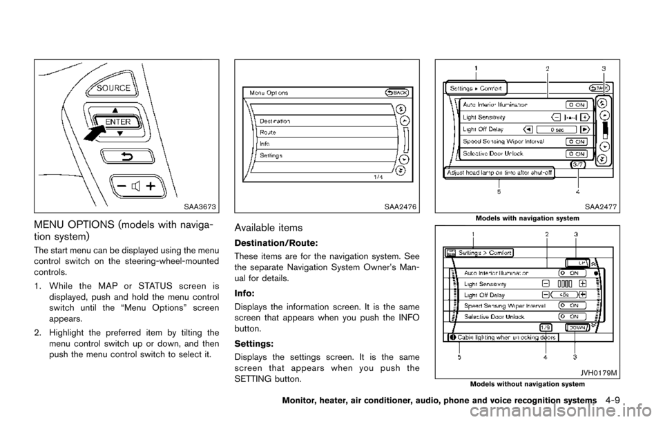
MENU OPTIONS (models with naviga-
tion system)
The start menu can be displayed using the menu
control switch on the steering-wheel-mounted
controls.
1. While the MAP or STATUS screen isdisplayed, push and hold the menu control
switch until the “Menu Options” screen
appears.
2. Highlight the preferred item by tilting the menu control switch up or down, and then
push the menu control switch to select it.
SAA2476
Available items
Destination/Route:
These items are for the navigation system. See
the separate Navigation System Owner’s Man-
ual for details.
Info:
Displays the information screen. It is the same
screen that appears when you push the INFO
button.
Settings:
Displays the settings screen. It is the same
screen that appears when you push the
SETTING button.
SAA2477
Models with navigation system
JVH0179MModels without navigation system
Monitor, heater, air conditioner, audio, phone and voice recognition systems4-9
Page 215 of 520
4-26Monitor, heater, air conditioner, audio, phone and voice recognition systems
SAA1896
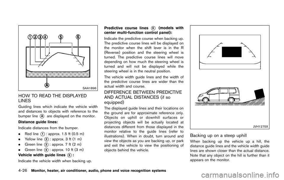
HOW TO READ THE DISPLAYED
LINES
Guiding lines which indicate the vehicle width
and distances to objects with reference to the
bumper line
*Aare displayed on the monitor.
Distance guide lines:
Indicate distances from the bumper.
. Red line
*1: approx. 1.5 ft (0.5 m)
. Yellow line
*2: approx. 3 ft (1 m)
. Green line
*3: approx. 7 ft (2 m)
. Green line
*4: approx. 10 ft (3 m)
Vehicle width guide lines
*5:
Indicate the vehicle width when backing up. Predictive course lines
*6(models with
center multi-function control panel):
Indicate the predictive course when backing up.
The predictive course lines will be displayed on
the monitor when the shift lever is in the R
(Reverse) position and the steering wheel is
turned. The predictive course lines will move
depending on how much the steering wheel is
turned and will not be displayed while the
steering wheel is in the neutral position.
The vehicle width guide lines and the width of
the predictive course lines are wider than the
actual width and course.
DIFFERENCE BETWEEN PREDICTIVE
AND ACTUAL DISTANCES (if so
equipped)
The displayed guide lines and their locations on
the ground are for approximate reference only.
Objects on uphill or downhill surfaces or
projecting objects will be actually located at
distances different from those displayed in the
monitor relative to the guide lines (refer to
illustrations) . When in doubt, turn around and
view the objects as you are backing up, or park
and exit the vehicle to view the positioning of
objects behind the vehicle.
JVH1275X
Backing up on a steep uphill
When backing up the vehicle up a hill, the
distance guide lines and the vehicle width guide
lines are shown closer than the actual distance.
Note that any object on the hill is further than it
appears on the monitor.
Page 217 of 520
4-28Monitor, heater, air conditioner, audio, phone and voice recognition systems
course.
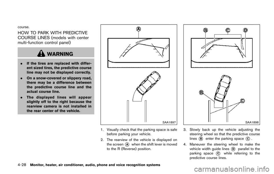
HOW TO PARK WITH PREDICTIVE
COURSE LINES (models with center
multi-function control panel)
WARNING
.If the tires are replaced with differ-
ent sized tires, the predictive course
line may not be displayed correctly.
. On a snow-covered or slippery road,
there may be a difference between
the predictive course line and the
actual course line.
. The displayed lines will appear
slightly off to the right because the
rearview camera is not installed in
the rear center of the vehicle.
SAA1897
1. Visually check that the parking space is safe
before parking your vehicle.
2. The rearview of the vehicle is displayed on the screen
*Awhen the shift lever is moved
to the R (Reverse) position.
SAA1898
3. Slowly back up the vehicle adjusting the steering wheel so that the predictive course
lines
*Benter the parking space*C.
4. Maneuver the steering wheel to make the vehicle width guide lines
*Dparallel to the
parking space
*Cwhile referring to the
predictive course lines.