navigation NISSAN ROGUE 2015 2.G Owners Manual
[x] Cancel search | Manufacturer: NISSAN, Model Year: 2015, Model line: ROGUE, Model: NISSAN ROGUE 2015 2.GPages: 440, PDF Size: 4.71 MB
Page 3 of 440
For descriptions specified for all-wheel drive
models, anAWDmark is placed at the beginning
of the applicable sections/items.
As with other vehicles with features for
off-road use, failure to operate all-wheel
drive models correctly may result in loss of
control or an accident. Be sure to read
“Driving safety precautions” in the “Start-
ing and driving” section of this manual.
ON-PAVEMENT AND OFF-ROAD DRIV-
ING
This vehicle will handle and maneuver
differently from an ordinary passenger
car because it has a higher center of
gravity for off-road use. As with other
vehicles with features of this type, fail-
ure to operate this vehicle correctly may
result in loss of control or an accident.
For additional information, refer to “On-
pavement and off-road driving
precautions,” “Avoiding collision and
rollover” and “Driving safety precau-
tions” in the “Starting and driving” sec-
tion of this manual.
MODIFICATION OF YOUR VEHICLE
This vehicle should not be modified.
Modification could affect its
performance, safety or durability and may
even violate governmental regulations. In
addition, damage or performance prob-
lems resulting from modifications may
not be covered under NISSAN warranties. This manual includes information for all features
and equipment available on this model. Features
and equipment in your vehicle may vary depend-
ing on model, trim level, options selected, order,
date of production, region or availability. There-
fore, you may find information about features or
equipment that are not included or installed on
your vehicle.
All information, specifications and illustrations in
this manual are those in effect at the time of
printing. NISSAN reserves the right to change
specifications, performance, design or compo-
nent suppliers without notice and without obliga-
tion. From time to time, NISSAN may update or
revise this manual to provide Owners with the
most accurate information currently available.
Please carefully read and retain with this manual
all revision updates sent to you by NISSAN to
ensure you have access to accurate and up-to-
date information regarding your vehicle. Current
versions of vehicle Owner’s Manuals and any
updates can also be found in the Owner section
of the NISSAN website at
https://owners.nissanusa.com/nowners/
navigation/manualsGuide. If you have ques-
tions concerning any information in your Owner’s
Manual, contact NISSAN Consumer Affairs. See
the NISSAN CUSTOMER CARE PROGRAM
page in this Owner’s Manual for contact informa-
tion.
WHEN READING THE MANUAL
Page 15 of 440
1. Vent (P. 4-24)
2. Headlight/fog light (if so equipped)/turnsignal switch (P. 2-34)
3. Meters, gauges, warning/indicator
lights and Vehicle Information Display
(P. 2-3, P. 2-7, P. 2-15) 4. Windshield wiper/washer switch and
rear window wiper/washer switch
(P. 2-31)
Ignition switch (if so equipped)
(P. 5-10) 5. Push-button ignition switch
(if so equipped) (P. 5-13)
6. Vent (P. 4-24)
7. Hazard warning flasher switch (P. 6-2)
8. Radio (P. 4-44)/Navigation system*
(if so equipped)
9. Front passenger supplemental air bag
(P. 2-29)
10. Glove box (P. 2-44)
11. Heater and air conditioning controls
(P. 4-25)
12. Power outlet (P. 2-42)
13. Shift lever (P. 5-18)
14. Auxiliary jack (P. 4-60) USB port (P. 4-60)
15. Front passenger air bag status light
(P. 2-29)
16. Cruise control main/set switches
(P. 5-30
Bluetooth Hands-Free Phone System
(if so equipped) (P. 4-36)
17. Driver supplemental air bag/Horn
(P. 1-46, P. 2-38)
18. Control panel and Vehicle Information
Display switches (P. 2-16)
19. Hood release (P. 3-24) Fuel door release (P. 3-30)
LIC2626
INSTRUMENT PANEL
0-6Illustrated table of contents
Page 16 of 440
20. Vehicle Dynamic Control (VDC) OFFswitch (P. 2-40)
Sport mode switch (P. 2-40)
ECO mode switch (if so equipped)
(P. 5-22)
Power liftgate switch (if so equipped)
(P.3-28)
Power liftgate main switch
(if so equipped) (P. 3-28)
Warning systems switch
(if so equipped) (P. 2-42)
All-Wheel Drive (AWD) lock switch
(if so equipped) (P. 2-40)
Hill descent control switch (if so
equipped) (P. 2-41)
21. Instrument brightness control (P. 2-34) Twin trip odometer reset switch (P. 2-3)
*: Refer to the separate Navigation System Own-
er’s Manual (if so equipped) .
Refer to the page number indicated in pa-
rentheses for operating details.
Illustrated table of contents0-7
Page 87 of 440
1. Vent (P. 4-24)
2. Headlight/fog light (if so equipped)/turnsignal switch (P. 2-34)
3. Meters, gauges, warning/indicator
lights and Vehicle Information Display
(P. 2-3, P. 2-7, P. 2-15) 4. Windshield wiper/washer switch and
rear window wiper/washer switch
(P. 2-31)
Ignition switch (if so equipped)
(P. 5-10) 5. Push-button ignition switch
(if so equipped) (P. 5-13)
6. Vent (P. 4-24)
7. Hazard warning flasher switch (P. 6-2)
8. Radio (P. 4-44)/Navigation system*
(if so equipped)
9. Front passenger supplemental air bag
(P. 2-29)
10. Glove box (P. 2-44)
11. Heater and air conditioning controls
(P. 4-25)
12. Power outlet (P. 2-42)
13. Shift lever (P. 5-18)
14. Auxiliary jack (P. 4-60) USB port (P. 4-60)
15. Front passenger air bag status light
(P. 2-29)
16. Cruise control main/set switches
(P. 5-30
Bluetooth Hands-Free Phone System
(if so equipped) (P. 4-36)
17. Driver supplemental air bag/Horn
(P. 1-46, P. 2-38)
18. Control panel and Vehicle Information
Display switches (P. 2-16)
19. Hood release (P. 3-24) Fuel door release (P. 3-30)
LIC2626
INSTRUMENT PANEL
2-2Instruments and controls
Page 88 of 440
20. Vehicle Dynamic Control (VDC) OFFswitch (P. 2-40)
Sport mode switch (P. 2-40)
ECO mode switch (if so equipped)
(P. 5-22)
Power liftgate switch (if so equipped)
(P.3-28)
Power liftgate main switch
(if so equipped) (P. 3-28)
Warning systems switch (if so
equipped) (P. 2-42)
All-Wheel Drive (AWD) lock switch
(if so equipped) (P. 2-40)
Hill descent control switch
(if so equipped) (P. 2-41)
21. Instrument brightness control (P. 2-34) Twin trip odometer reset switch (P. 2-3)
*: Refer to the separate Navigation System Own-
er’s Manual (if so equipped) .
Refer to the page number indicated in pa-
rentheses for operating details.
1. Tachometer
2. Warning/indicator lights
3. Vehicle Information Display/Odometer/
Twin trip odometer
4. Speedometer
5. Fuel gauge 6. Engine coolant temperature gauge
LIC2627
METERS AND GAUGES
Instruments and controls2-3
Page 102 of 440
– Lane (LDW) On/Off (if so equipped)
– Blind Spot (BSW) On/Off (if soequipped)
● Parking Aids (if so equipped)
– Moving Object On/Off (if so equipped)
● Chassis Control
– Trace Control – For additional informa- tion, refer to “Active Trace Control” in
“Starting and Driving” section of this
manual.
– Engine Brake – For additional informa- tion, refer to “Active Engine Brake” in
“Starting and Driving” section of this
manual.
Clock
For additional information on how to set the
clock, refer to the “Monitor, climate, audio, phone
and voice recognition systems” section of this
manual or the separate Navigation Owner’s
Manual.
Meter Settings
The meter settings allows the customer to
choose from the various meter selections. The meter settings can be changed using
the
,, and the ENTER buttons.
Main Menu Selection
The items that display can be enabled/disabled
when the ignition switch is placed in the ON
position. To change the items that display.
Use the
button to select and the ENTER
button to change a menu item:
● Trip Computer – For additional information,
refer to “Trip Computer” in this section.
● Range
● Average Speed
● Fuel Economy
● Navigation (if so equipped)
● Audio/Satellite Radio (if so equipped)
● Driving Aids (if so equipped)
● Tire Pressures
● Chassis Control
● Warning Confirmation
Body Color
The color of the vehicle that displays in the ve-
hicle information display when the ignition switch
is placed in the ON position can be changed. ECO Mode Settings
The following information can be
enabled/disabled to display in the vehicle infor-
mation display when the ignition switch is placed
in the ON position.
From the “Main Menu Selection” select “ECO
Mode Settings” to display the information when
the ignition switch is placed in the ON position.
● Select “Display” then ”On” or “Off” to display
“Pedal (if so equipped)” or “Inst.FE (Instant
Fuel Economy)” in the vehicle information
display when the ignition switch is placed in
the ON position.
ECO Drive Report
The following information can be
enabled/disabled to display in the vehicle infor-
mation display when the ignition switch is placed
in the ON position.
From the “Main Menu Selection” select “ECO
Drive Report” to display the information when the
ignition switch is placed in the ON position. ● Select “Display” then “On” or “Off” to display
the information when the ignition switch is
placed in the ON position. The ECO Drive
Report is displayed when the ignition switch
is in the OFF position.
Instruments and controls2-17
Page 105 of 440
Average fuel consumption
The average fuel consumption mode shows the
average fuel consumption since the last reset.
Resetting is done by pushing the
button
for longer than one second.
The display is updated every 30 seconds. At
about the first 1/3 mile (500 m) after a reset, the
display shows “_ _”.
2. Average speed (MPH or km/h)
The average speed mode shows the average
vehicle speed since the last reset. Resetting is
done by pushing the
button for longer than
one second.
The display is updated every 30 seconds. At
about the first 1/3 mile (500 m) after a reset, the
display shows “_ _”.
3. Elapsed time and trip odometer (mile or
km)
Elapsed time
The elapsed time mode shows the time since the
last reset. Resetting is done by pushing
the
button for longer than one second.
(The trip odometer is also reset at same time.)
Trip odometer
The trip odometer mode shows the total distance
the vehicle has been driven since the last reset. Resetting is done by pushing the
button
for longer than one second. (The elapsed time is
also reset at same time.)
4. Distance to empty (dte – mile or km)
The distance to empty (dte) mode provides you
with an estimation of the distance that can be
driven before refueling. The dte is constantly be-
ing calculated, based on the amount of fuel in the
fuel tank and the actual fuel consumption.
The display is updated approximately every
30 seconds.
The dte mode includes a low range warning
feature. If the fuel level is low, the warning is
displayed on the screen.
When the fuel level drops even lower, the dte
display wil change to “_ _”.
● If the amount of fuel added is small, the
display just before the ignition switch is
pushed to the OFF position may continue to
be displayed.
● When driving uphill or rounding curves, the
fuel in the tank shifts, which may momentarily
change the display.
5. Navigation (if so equipped)
When the route guidance is set in the navigation
system, this item shows the navigation route in-
formation. 6. Audio
The audio mode shows the status of audio infor-
mation.
7. Driving aids (if so equipped)
The driving aids mode shows the operating con-
dition for the following systems.
● Lane Departure Warning (LDW)
● Blind Spot Warning (BSW)
● Forward Collision Warning (FCW)
For additional information, refer to “Blind Spot
Warning (BSW) system/Lane Departure Warn-
ing (LDW) system” and “Forward Collision Warn-
ing (FCW) system” in “Starting and diving” sec-
tion of this manual.
8. Tire pressure
The tire pressure mode shows the pressure of all
four tires while the vehicle is driven. The axle
between the tires will also display the recom-
mended tire pressure.
When the “Tire Pressure Low Add Air” or “Flat
Tire - Visit Dealer” (if so equipped) warning ap-
pears, the display can be switched to the tire
pressure mode by pushing the
button.
The tire pressure unit can be changed in the
TPMS setting under the Settings menu on the
2-20Instruments and controls
Page 108 of 440
WARNING
The tire replacement indicator is not a
substitute for regular tire checks, includ-
ing tire pressure checks. For additional
information, refer to “Changing wheels
and tires” in the “Maintenance and do-it-
yourself” section of this manual. Many fac-
tors including tire inflation, alignment,
driving habits and road conditions affect
tire wear and when tires should be re-
placed. Setting the tire replacement indi-
cator for a certain driving distance does
not mean your tires will last that long. Use
the tire replacement indicator as a guide
only and always perform regular tire
checks. Failure to perform regular tire
checks, including tire pressure checks
could result in tire failure. Serious vehicle
damage could occur and may lead to a
collision, which could result in serious
personal injury or death.
Other
This indicator appears when the customer set
distance is reached for checking or replacing
maintenance items other than the engine oil, oil
filter and tires. Other maintenance items can in-
clude such things as air filter or tire rotation. The
distance for checking or replacing the items can
be set or reset.
Alarm
This setting allows the customer to set alarms for
outside temperature and a timer alert.
1. Press the
button.
2. Use the
button until “Settings” is se-
lected, and press ENTER.
3. Select “Alarm” using the
button and
press ENTER.
Outside Temperature
This setting allows the customer to
enable/disable the alert for low outside tempera-
ture in the vehicle information display.
1. Use the
button to select “Outside
Temperature”.
2. Press the ENTER button to turn on/off the outside temperature in the vehicle informa-
tion display.
Timer Alert
This setting allows the driver to set an alert to
notify a set time has been reached.
1. Use the
button to select “Timer Alert”.
2. Press the ENTER button. 3. To change the timer amount, use the
button and the ENTER button to save the
selected time amount.
Navigation (if so equipped)
This setting allows the customer to
enable/disable the alert for navigation in the ve-
hicle information display.
1. Use the
buttons to select “Naviga-
tion”.
2. Press the ENTER button to turn ON/OFF the alert.
Phone (if so equipped)
This setting allows the customer to
enable/disable the alert for navigation in the ve-
hicle information display.
1. Use the
buttons to select “Phone”.
2. Press the ENTER button to turn ON/OFF the alert.
Mail (if so equipped)
This setting allows the customer to
enable/disable the alert for navigation in the ve-
hicle information display.
1. Use the
buttons to select “Mail”.
2. Press the ENTER button to turn ON/OFF the alert.
Instruments and controls2-23
Page 109 of 440
Units
The units that are shown in the vehicle informa-
tion display can be changed:● Mileage
● Tire pressures
● Temperature
Use the
,, and the ENTER buttons to
select and change the units of the vehicle infor-
mation display. The units of the navigation screen
can be changed independently of the vehicle
information display. For vehicles equipped with
Navigation, refer to “How to use the
but-
ton” in the “Monitor, climate, audio, phone and
voice recognition systems” section of this
manual.
Mileage
The unit for the mileage that displays in the ve-
hicle information display can be changed to:
● miles, MPG
● km/h, km/l
● km/h, l/100km
Use the
and the ENTER buttons to select
and change the unit. Tire Pressures
The unit for tire pressure that displays in the
vehicle information display can be changed to:
● psi
● kPa
● bar
● Kgf/cm
2
Use theand the ENTER buttons to select
and change the unit.
Temperature
The temperature that displays in the vehicle infor-
mation display can be changed from:
● °F (Fahrenheit)
● °C (Celsius)
Use the ENTER button to toggle choices.
Language
The language of the vehicle information display
can be changed to: ● US English
● French
● Spanish Use the
,, and the ENTER buttons to
select and change the language of the vehicle
information display. The language of the center
display/navigation can be changed indepen-
dently of the vehicle information display. For ve-
hicles not equipped with Navigation refer to
“ENTER/SETTING button:” and vehicles
equipped with Navigation refer to “How to use
the
button” in the “Monitor, climate, au-
dio, phone and voice recognition systems” sec-
tion of this manual.
Factory Reset
The settings in the vehicle information display can
be reset back to the factory default. To reset the
vehicle information display:
1. Press the
button.
2. Use the
buttons to select “Settings”,
and press the ENTER button.
3. Select “Factory Reset” using the
but-
tons and press the ENTER button.
4. Select “YES” to return all settings back to default by pressing the ENTER button.
2-24Instruments and controls
Page 151 of 440
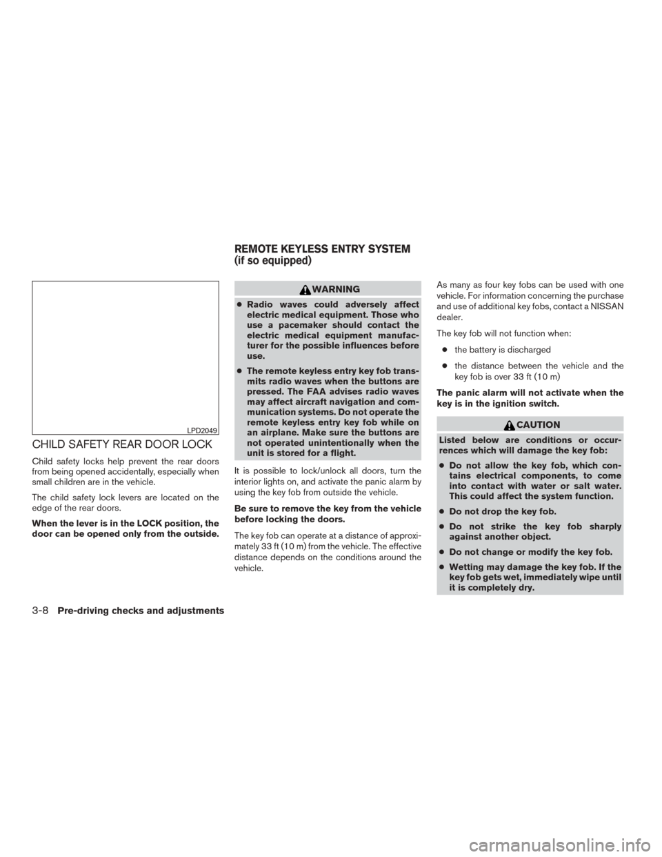
CHILD SAFETY REAR DOOR LOCK
Child safety locks help prevent the rear doors
from being opened accidentally, especially when
small children are in the vehicle.
The child safety lock levers are located on the
edge of the rear doors.
When the lever is in the LOCK position, the
door can be opened only from the outside.
WARNING
●Radio waves could adversely affect
electric medical equipment. Those who
use a pacemaker should contact the
electric medical equipment manufac-
turer for the possible influences before
use.
● The remote keyless entry key fob trans-
mits radio waves when the buttons are
pressed. The FAA advises radio waves
may affect aircraft navigation and com-
munication systems. Do not operate the
remote keyless entry key fob while on
an airplane. Make sure the buttons are
not operated unintentionally when the
unit is stored for a flight.
It is possible to lock/unlock all doors, turn the
interior lights on, and activate the panic alarm by
using the key fob from outside the vehicle.
Be sure to remove the key from the vehicle
before locking the doors.
The key fob can operate at a distance of approxi-
mately 33 ft (10 m) from the vehicle. The effective
distance depends on the conditions around the
vehicle. As many as four key fobs can be used with one
vehicle. For information concerning the purchase
and use of additional key fobs, contact a NISSAN
dealer.
The key fob will not function when:
● the battery is discharged
● the distance between the vehicle and the
key fob is over 33 ft (10 m)
The panic alarm will not activate when the
key is in the ignition switch.
CAUTION
Listed below are conditions or occur-
rences which will damage the key fob:
● Do not allow the key fob, which con-
tains electrical components, to come
into contact with water or salt water.
This could affect the system function.
● Do not drop the key fob.
● Do not strike the key fob sharply
against another object.
● Do not change or modify the key fob.
● Wetting may damage the key fob. If the
key fob gets wet, immediately wipe until
it is completely dry.LPD2049
REMOTE KEYLESS ENTRY SYSTEM
(if so equipped)
3-8Pre-driving checks and adjustments