service indicator NISSAN ROGUE 2021 Owner´s Manual
[x] Cancel search | Manufacturer: NISSAN, Model Year: 2021, Model line: ROGUE, Model: NISSAN ROGUE 2021Pages: 556, PDF Size: 2.7 MB
Page 152 of 556
2-64Instruments and controls
.Any liquid spilled on the heated
seat should be removed immedi-
ately with a dry cloth.
. When cleaning the seat, never use
gasoline, thinner, or any similar
materials.
. If any malfunctions are found or
the heated seat does not operate,
turn the switch off and have the
system checked. It is recom-
mended you visit a NISSAN dealer
for this service.
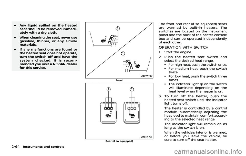
WAC0524XFront
WAC0525XRear (if so equipped)
The front and rear (if so equipped) seats
are warmed by built-in heaters. The
switches are located on the instrument
panel and the back of the center console
box and can be operated independently
of each other.
OPERATION WITH SWITCH
1. Start the engine.
2. Push the heated seat switch and
select the desired heat range.
.For high heat, push the switch once..For medium heat, push the switchtwice.
.For low heat, push the switch three
times.
.The indicator lighton the switch
will illuminate depending on the
heat level when the heater is on.
3. To turn off the heater, push the heated seat switch until the indicator
light turns off.
The heater is controlled by a control
module, automatically adjusting the
heat level to maintain comfort accord-
ing to the selected heat range.
The indicator light will remain on as
long as the switch is on.
When the vehicle’s interior is warmed,
or before you leave the vehicle, be
sure to turn off the seat heater.
Page 159 of 556

WAC0491X
Making an emergency call
The Emergency Call (SOS) button is lo-
cated near the map light.
1. Push the cover to expose the Emer-gency Call (SOS) button
.
2. Push the Emergency Call (SOS) button to make an emergency call.
3. When the line is connected, speak to the Response Specialist.
If you want to cancel the emergency call,
push and hold the Emergency Call (SOS)
button for a few seconds. NOTE:
.
After the Emergency Call (SOS) but-
ton is pushed, it may take some time
until the system initiates connec-
tion, depending on the technical
environment and whether the TCU
(Telematics Control Unit) is being
used by other services.
. An indicator light on the Emergency
Call (SOS) button shows the readi-
ness of the emergency support sys-
tem. If the indicator light is not
illuminated, pushing the Emergency
Call (SOS) button does not connect
your vehicle to the Response Spe-
cialist.
The indicator light blinks while con-
nected to the NissanConnect® Ser-
vices Response Center.
. Even when the indicator light is
illuminated, connection to the Nis-
sanConnect® Services Response
Center may not be possible. If this
occurs in an emergency situation,
contact the authorities by other
means.
. To avoid disconnecting the line,
keep the engine running during an
emergency call, if it is safe to do so.
CUP HOLDERS
CAUTION
.Avoid abrupt starting and braking
when the cup holder is being
used to prevent spilling the drink.
If the liquid is hot, it can scald you
or your passenger.
. Use only soft cups in the cup
holder. Hard objects can injure
you in an accident.
Instruments and controls2-71
STORAGE
Page 260 of 556
5-6Starting and driving
THREE-WAY CATALYST
The three-way catalyst is an emission
control device installed in the exhaust
system. Exhaust gases in the three-way
catalyst are burned at high temperatures
to help reduce pollutants.
WARNING
.The exhaust gas and the exhaust
system are very hot. Keep people,
animals and flammable materials
away from the exhaust system
components.
. Do not stop or park the vehicle
over flammable materials such as
dry grass, wastepaper or rags.
They may ignite and cause a fire.
CAUTION
.Do not use leaded gasoline. De-
posits from leaded gasoline will
seriously reduce the three-way
catalyst’s ability to help reduce
exhaust pollutants.
. Keep your engine tuned up. Mal-
functions in the ignition, fuel in-
jection, or electrical systems can cause overrich fuel flow into the
three-way catalyst, causing it to
overheat. Do not keep driving if
the engine misfires, or if notice-
able loss of performance or other
unusual operating conditions are
detected. Have the vehicle in-
spected. It is recommended you
visit a NISSAN dealer for this
service.
. Avoid driving with an extremely
low fuel level. Running out of fuel
could cause the engine to misfire,
damaging the three-way catalyst.
. Do not race the engine while
warming it up.
. Do not push or tow your vehicle
to start the engine.
TIRE PRESSURE MONITORING SYS-
TEM (TPMS)
Each tire, including the spare, should be
checked monthly when cold and inflated
to the inflation pressure recommended
by the vehicle manufacturer on the ve-
hicle placard or tire inflation pressure
label. (If your vehicle has tires of a
different size than the size indicated on
the vehicle placard or tire inflation pres-
sure label, you should determine the
proper tire inflation pressure for those tires.)
As an added safety feature, your vehicle
has been equipped with a Tire Pressure
Monitoring System (TPMS) that illumi-
nates a low tire pressure telltale when
one or more of your tires is significantly
under-inflated. Accordingly, when the low
tire pressure telltale illuminates, you
should stop and check your tires as soon
as possible, and inflate them to the
proper pressure. Driving on a significantly
under-inflated tire causes the tire to
overheat and can lead to tire failure.
Under-inflation also reduces fuel effi-
ciency and tire tread life, and may affect
the vehicle’s handling and stopping abil-
ity.
Please note that the TPMS is not a
substitute for proper tire maintenance,
and it is the driver’s responsibility to
maintain correct tire pressure, even if
under-inflation has not reached the level
to trigger illumination of the TPMS low
tire pressure telltale.
Your vehicle has also been equipped with
a TPMS malfunction indicator to indicate
when the system is not operating prop-
erly. The TPMS malfunction indicator is
combined with the low tire pressure tell-
tale. When the system detects a malfunc-
tion, the telltale will flash for
approximately one minute and then re-
Page 276 of 556
5-22Starting and driving
N (Neutral):
Neither the forward nor reverse gear is
engaged. The engine can be started in
this position. You may shift to the N
(Neutral) position and restart a stalled
engine while the vehicle is moving.
You can select this position by holding
the shift lever at this position for 0.5
seconds.
D (Drive):
Use this position for all normal forward
driving. The CVT changes gears automa-
tically. All forward gears are available.If
the vehicle is placed in the D (Drive)
position while the vehicle is reversing,
the chime will sound and the vehicle will
switch into the N (Neutral) position.
Neutral hold mode function
This function enables you to turn off the
engine with the vehicle in the N (Neutral)
position. While this function is activated,
the vehicle can be moved by pushing with
hand (when car washing) even if the
ignition switch is in the OFF position.
When using this function, release the
electronic parking brake.
WARNING
. Use this function on a level sur-
face only. Failure to do so may
cause the vehicle to move acci-
dentally and could result in a
collision or serious personal in-
jury.
. Do not use this function for a
purpose other than car washing.
. When the ignition switch is placed
in the ON position after activating
this function, depress the brake
pedal to stop the vehicle because
the shift lever is in the N (Neutral)
position.
. If this function is not activated
regardless of proper operation,
transmission may malfunction. It
is recommended that you visit a
NISSAN dealer for this service.
To activate the Neutral hold mode, per-
form the following operations.
1. Push the ignition switch to start the engine.
2. Release the electronic parking brake.
3. Depress and hold the brake pedal. 4. Push the P position switch.
5. Slide the shift lever to the N (Neutral)
position, and hold it for 0.5 second
until “N” appears in the vehicle infor-
mation display.
6. Slide the shift lever to the N (Neutral) position again, and hold it for 0.5
second, until a message “Neutral Hold
Mode has been activated” appears in
the vehicle information display. (See
“66. Neutral Hold Mode activated in-
dicator” (P.2-42).)
7. Place the ignition switch in the OFF position. The engine will turn off with
holding the N (Neutral) position.
To exit the Neutral hold mode, place the
vehicle in other than N (Neutral) position.
NOTE:
. It is necessary to perform the steps
4 through 6 within approximately 5
seconds to prevent incorrect opera-
tion.
. When the ignition switch is placed in
the OFF position while the shift lever
is in the N (Neutral) position, a
message will appear in the vehicle
information display. (See “65. Neu-
tral Hold Mode guidance indicator”
(P.2-42).)
. If the Neutral hold mode is unavail-
able, a message will appear in the
Page 282 of 556
5-28Starting and driving
The automatic brake hold function main-
tains the braking force without the driver
having to depress the brake pedal when
the vehicle is stopped at a traffic light or
intersection. As soon as the driver de-
presses the accelerator pedal again, the
automatic brake hold function is deacti-
vated and the braking force is released.
The operating status of the automatic
brake hold can be displayed on the
vehicle information display.
WARNING
.The automatic brake hold func-
tion is not designed to hold the
vehicle on a steep hill or slippery
road. Never use the automatic
brake hold when the vehicle is
stopped on a steep hill or slippery
road. Failure to do so may cause
the vehicle to move.
. The automatic brake hold warn-
ing may appear in the vehicle
information display to request
that the driver retake control by
depressing the brake pedal.
. When the automatic brake hold
function is activated but fails to
maintain the vehicle at a stand-
still, depress the brake pedal to
stop the vehicle. If the vehicle unexpectedly moves due to out-
side conditions, the chime may
sound and automatic brake hold
warning may illuminate in the
vehicle information display.
. Be sure to deactivate the auto-
matic brake hold function when
using a car wash or towing your
vehicle.
. Make sure to push the park but-
ton to shift to the P (Park) posi-
tion and apply the electronic
parking brake when parking your
vehicle, riding on or off the vehi-
cle, or loading luggage. Failure to
do so could cause the vehicle to
move or roll away unexpectedly
and result in serious personal
injury or property damage.
. If any of the following conditions
occur, the automatic brake hold
function may not function. Have
the system checked promptly. It
is recommended that you visit a
NISSAN dealer for this service.
Failure to operate the vehicle in
accordance with these conditions
could cause the vehicle to move
or roll away unexpectedly and
result in serious personal injury
or property damage. — A warning message appears
in the vehicle information dis-
play.
— The indicator light on the automatic brake hold switch
does not illuminate when the
switch is pushed.
. The automatic brake hold func-
tion will not be activated if the
slip indicator light, electronic
parking brake system warning
light or master warning light illu-
minates and the Chassis Control
System Error warning message
appears in the vehicle informa-
tion display.
. To maintain the braking force to
keep the vehicle to a standstill, a
noise may be heard. This is not a
malfunction.
AUTOMATIC BRAKE HOLD
Page 310 of 556
5-56Starting and driving
the engine off and restart the engine. If
the I-LI indicator (orange) continues to
illuminate, have the I-LI system checked. It
is recommended that you visit a NISSAN
dealer for this service.
WAC0523X
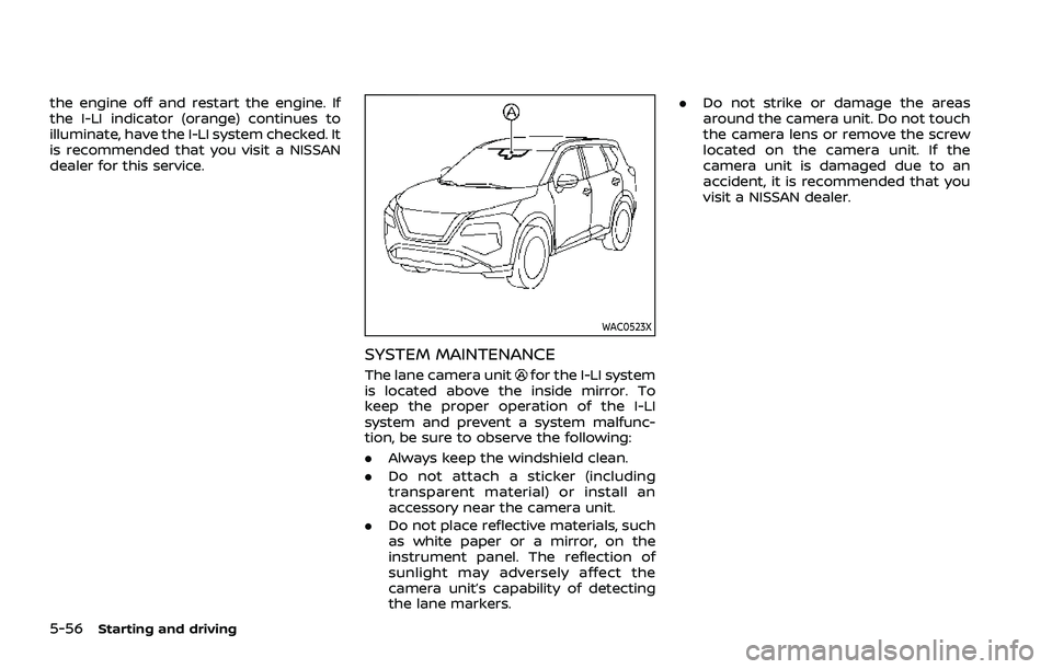
SYSTEM MAINTENANCE
The lane camera unitfor the I-LI system
is located above the inside mirror. To
keep the proper operation of the I-LI
system and prevent a system malfunc-
tion, be sure to observe the following:
. Always keep the windshield clean.
. Do not attach a sticker (including
transparent material) or install an
accessory near the camera unit.
. Do not place reflective materials, such
as white paper or a mirror, on the
instrument panel. The reflection of
sunlight may adversely affect the
camera unit’s capability of detecting
the lane markers. .
Do not strike or damage the areas
around the camera unit. Do not touch
the camera lens or remove the screw
located on the camera unit. If the
camera unit is damaged due to an
accident, it is recommended that you
visit a NISSAN dealer.
Page 317 of 556
WAF0555XIllustration 6 – Entering from the side
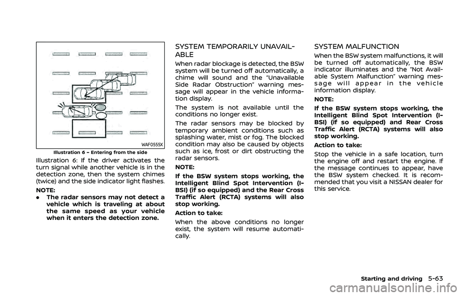
Illustration 6: If the driver activates the
turn signal while another vehicle is in the
detection zone, then the system chimes
(twice) and the side indicator light flashes.
NOTE:
.The radar sensors may not detect a
vehicle which is traveling at about
the same speed as your vehicle
when it enters the detection zone.
SYSTEM TEMPORARILY UNAVAIL-
ABLE
When radar blockage is detected, the BSW
system will be turned off automatically, a
chime will sound and the “Unavailable
Side Radar Obstruction” warning mes-
sage will appear in the vehicle informa-
tion display.
The system is not available until the
conditions no longer exist.
The radar sensors may be blocked by
temporary ambient conditions such as
splashing water, mist or fog. The blocked
condition may also be caused by objects
such as ice, frost or dirt obstructing the
radar sensors.
NOTE:
If the BSW system stops working, the
Intelligent Blind Spot Intervention (I-
BSI) (if so equipped) and the Rear Cross
Traffic Alert (RCTA) systems will also
stop working.
Action to take:
When the above conditions no longer
exist, the system will resume automati-
cally.
SYSTEM MALFUNCTION
When the BSW system malfunctions, it will
be turned off automatically, the BSW
indicator illuminates and the “Not Avail-
able System Malfunction” warning mes-
sage will appear in the vehicle
information display.
NOTE:
If the BSW system stops working, the
Intelligent Blind Spot Intervention (I-
BSI) (if so equipped) and Rear Cross
Traffic Alert (RCTA) systems will also
stop working.
Action to take:
Stop the vehicle in a safe location, turn
the engine off and restart the engine. If
the message continues to appear, have
the BSW system checked. It is recom-
mended that you visit a NISSAN dealer for
this service.
Starting and driving5-63
Page 328 of 556
5-74Starting and driving
JVS0742XIllustration 10 - Entering from the side
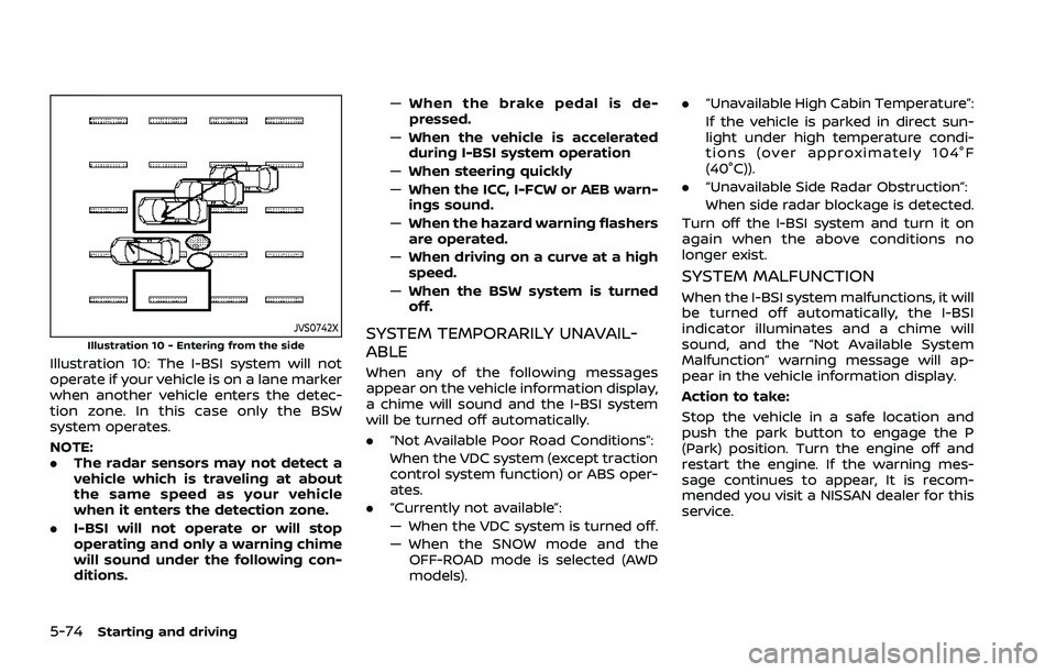
Illustration 10: The I-BSI system will not
operate if your vehicle is on a lane marker
when another vehicle enters the detec-
tion zone. In this case only the BSW
system operates.
NOTE:
.The radar sensors may not detect a
vehicle which is traveling at about
the same speed as your vehicle
when it enters the detection zone.
. I-BSI will not operate or will stop
operating and only a warning chime
will sound under the following con-
ditions. —
When the brake pedal is de-
pressed.
— When the vehicle is accelerated
during I-BSI system operation
— When steering quickly
— When the ICC, I-FCW or AEB warn-
ings sound.
— When the hazard warning flashers
are operated.
— When driving on a curve at a high
speed.
— When the BSW system is turned
off.
SYSTEM TEMPORARILY UNAVAIL-
ABLE
When any of the following messages
appear on the vehicle information display,
a chime will sound and the I-BSI system
will be turned off automatically.
. “Not Available Poor Road Conditions”:
When the VDC system (except traction
control system function) or ABS oper-
ates.
. “Currently not available”:
— When the VDC system is turned off.
— When the SNOW mode and the
OFF-ROAD mode is selected (AWD
models). .
“Unavailable High Cabin Temperature”:
If the vehicle is parked in direct sun-
light under high temperature condi-
tions (over approximately 104°F
(40°C)).
. “Unavailable Side Radar Obstruction”:
When side radar blockage is detected.
Turn off the I-BSI system and turn it on
again when the above conditions no
longer exist.
SYSTEM MALFUNCTION
When the I-BSI system malfunctions, it will
be turned off automatically, the I-BSI
indicator illuminates and a chime will
sound, and the “Not Available System
Malfunction” warning message will ap-
pear in the vehicle information display.
Action to take:
Stop the vehicle in a safe location and
push the park button to engage the P
(Park) position. Turn the engine off and
restart the engine. If the warning mes-
sage continues to appear, It is recom-
mended you visit a NISSAN dealer for this
service.
Page 336 of 556
5-82Starting and driving
Operation is subject to the following
two conditions: (1) this device may not
cause interference, and (2) this device
must accept any interference, including
interference that may cause undesired
operation of the device.
WAF0421X
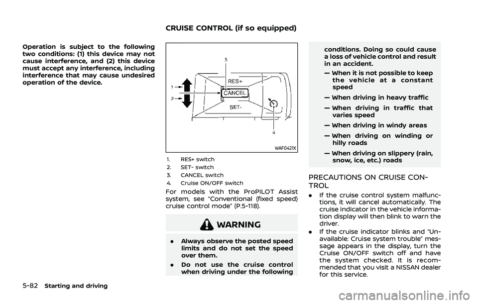
1. RES+ switch
2. SET- switch
3. CANCEL switch
4. Cruise ON/OFF switch
For models with the ProPILOT Assist
system, see “Conventional (fixed speed)
cruise control mode” (P.5-118).
WARNING
.Always observe the posted speed
limits and do not set the speed
over them.
. Do not use the cruise control
when driving under the following conditions. Doing so could cause
a loss of vehicle control and result
in an accident.
— When it is not possible to keep
the vehicle at a constant
speed
— When driving in heavy traffic
— When driving in traffic that varies speed
— When driving in windy areas
— When driving on winding or hilly roads
— When driving on slippery (rain, snow, ice, etc.) roads
PRECAUTIONS ON CRUISE CON-
TROL
. If the cruise control system malfunc-
tions, it will cancel automatically. The
cruise indicator in the vehicle informa-
tion display will then blink to warn the
driver.
. If the cruise indicator blinks and “Un-
available: Cruise system trouble” mes-
sage appears in the display, turn the
Cruise ON/OFF switch off and have
the system checked. It is recom-
mended that you visit a NISSAN dealer
for this service.
CRUISE CONTROL (if so equipped)
Page 411 of 556
tion, it switches the ABS off and illumi-
nates the ABS warning light on the
instrument panel. The brake system then
operates normally, but without anti-lock
assistance.
If the ABS warning light illuminates during
the self-test or while driving, have the
vehicle checked. It is recommended you
visit a NISSAN dealer for this service.
Normal operation
The ABS operates at speeds above 3 to 6
MPH (5 to 10 km/h). The speed varies
according to road conditions.
When the ABS senses that one or more
wheels are close to locking up, the
actuator rapidly applies and releases
hydraulic pressure. This action is similar
to pumping the brakes very quickly. You
may feel a pulsation in the brake pedal
and hear a noise from under the hood or
feel a vibration from the actuator when it
is operating. This is normal and indicates
that the ABS is operating properly. How-
ever, the pulsation may indicate that road
conditions are hazardous and extra care
is required while driving.The Vehicle Dynamic Control (VDC) sys-
tem uses various sensors to monitor
driver inputs and vehicle motion. Under
certain driving conditions, the VDC sys-
tem helps to perform the following func-
tions.
.
Controls brake pressure to reduce
wheel slip on one slipping drive wheel
so power is transferred to a non
slipping drive wheel on the same axle.
. Controls brake pressure and engine
output to reduce drive wheel slip
based on vehicle speed (traction con-
trol function).
. Controls brake pressure at individual
wheels and engine output to help the
driver maintain control of the vehicle
in the following conditions:
— understeer (vehicle tends to not
follow the steered path despite
increased steering input)
— oversteer (vehicle tends to spin due to certain road or driving condi-
tions).
The VDC system can help the driver to
maintain control of the vehicle, but it
cannot prevent loss of vehicle control in
all driving situations.
When the VDC system operates, the slip
indicator light
in the instrument panel
flashes so note the following: .
The road may be slippery or the
system may determine some action
is required to help keep the vehicle on
the steered path.
. You may feel a pulsation in the brake
pedal and hear a noise or vibration
from under the hood. This is normal
and indicates that the VDC system is
working properly.
. Adjust your speed and driving to the
road conditions.
If a malfunction occurs in the system, the
slip indicator light
illuminates in the
instrument panel. The VDC system auto-
matically turns off.
The vehicle information display is used to
turn off the VDC system. The VDC off
indicator
illuminates to indicate the
VDC system is off. When the VDC system
is turned off, the VDC system still oper-
ates to prevent one drive wheel from
slipping by transferring power to a non
slipping drive wheel. The slip indicator
light
flashes if this occurs. All other
VDC functions are off, and the slip in-
dicator light
will not flash. The VDC
system is automatically reset to on when
the ignition switch is placed in the off
position then back to the on position.
See “Slip indicator light” (P.2-20) and
“Vehicle Dynamic Control (VDC) off indi-
cator light” (P.2-20).
Starting and driving5-157
VEHICLE DYNAMIC CONTROL (VDC) SYSTEM