stop start engine NISSAN ROGUE 2023 Owner's Manual
[x] Cancel search | Manufacturer: NISSAN, Model Year: 2023, Model line: ROGUE, Model: NISSAN ROGUE 2023Pages: 508, PDF Size: 2.44 MB
Page 268 of 508
5-28Starting and driving
automatic brake hold function.
The electronic parking brake is automati-
cally released as soon as the vehicle
starts while the accelerator pedal is
depressed.
WARNING
.The electronic parking brake will
not be automatically applied
when the engine is stopped with-
out using the ignition switch (for
example, by engine stalling).
Without the vehicle stationary,
the electronic parking brake will
not be automatically applied
even if the engine is turned off
with the ignition switch.
. Before leaving the vehicle, move
the shift lever to the 1 (1st) or R
(Reverse) position and check that
the electronic parking brake in-
dicator light is illuminated to
confirm that the electronic park-
ing brake is applied. The electro-
nic parking brake indicator light
will remain on for a period of time
after the driver’s door is locked.
CAUTION
When parking in an area where the
outside temperature is below 32°F
(0°C), do not apply the parking brake
to prevent it from freezing.
For safe parking, place the shift lever
in the 1 (1st) or R (Reverse) position
and securely block the wheels.
NOTE:
. To keep the electronic parking brake
released after the engine is turned
off, place the ignition switch in the
OFF position, depress the brake
pedal and push down the parking
brake switch before opening the
driver’s door.
. If a malfunction occurs in the elec-
tronic parking brake system (for
example, due to battery discharge),
it is recommended to contact a
NISSAN dealer.
. If the shift lever is moved to the P
(Park) position when the brake force
is maintained by the automatic
brake hold function, the electronic
parking brake will apply automati-
cally. .
If the driver’s seat belt is unfastened
when the brake force is maintained
by the automatic brake hold func-
tion, the electronic parking brake
will apply automatically.
. If the ignition switch is placed in the
OFF position when the brake force is
maintained by the automatic brake
hold function, the electronic parking
brake will apply automatically.
Manual operation
The electronic parking brake will not be
automatically applied if the engine is
stopped without using the ignition switch
(for example, by engine stalling). In such a
case, you have to apply the parking brake
manually.
To apply: Pull the switch up
. The
indicator lightwill illuminate.
To release: With the ignition switch in the
ON position, depress the brake pedal and
push the switch down
. The indicator
lightwill turn off.
Before driving, check that the electronic
parking brake indicator light
goes
out. For additional information, see
“Warning lights, indicator lights and audi-
ble reminders” (P.2-10).
Page 272 of 508
5-32Starting and driving
applied and the brake force of the
automatic brake hold will be re-
leased:
—The braking force is applied by
the automatic brake hold function
for 3 minutes or longer.
— The driver’s seat belt is unfas-
tened.
— The ignition switch is placed in
the OFF position.
— If a malfunction occurs in the
automatic brake hold function.
. When the vehicle stops, but the
brake force is not automatically
applied, depress the brake pedal
firmly until the automatic brake hold
indicator light (green) illuminates.
Automatic brake hold function dis-
play
The automatic brake hold function status
can be checked in the “Chassis Control”
mode in the vehicle information display.
For additional information, see “Trip com-
puter” (P.2-40).
WAF0037X
The SPORT mode switch adjusts the
engine and transmission points to en-
hance performance. Push the SPORT
mode switch on the instrument panel to
activate the SPORT mode. The SPORT
mode indicator (drive mode indicator)
appears in the vehicle information dis-
play.
NOTE:
In the SPORT mode, fuel economy may
be reduced.
JVS0185X
The ECO mode system helps to enhance
the fuel economy by controlling the
engine and CVT operation (for CVT mod-
els) automatically to avoid rapid accelera-
tion.
To turn on the ECO mode system, push
the ECO switch. The ECO mode indicator
appears on the meter.
To turn off the ECO mode, push the ECO
switch again. The ECO mode indicator will
turn off.
.The ECO mode system cannot be
turned off while the accelerator pedal
is depressed even if the ECO switch is
pushed to OFF. Release the accelera-
tor pedal to turn off the ECO mode
SPORT MODE SWITCH (if so equipped)ECO MODE SYSTEM
Page 279 of 508

the LDW system will resume operating
automatically and the LDW indicator will
stop flashing.
Condition B:
The warning function of the LDW system
is not designed to work under the follow-
ing conditions:
.When you operate the lane change
signal and change traveling lanes in
the direction of the signal. (The LDW
system will become operable again
approximately 2 seconds after the
lane change signal is turned off.)
. When the vehicle speed lowers to less
than approximately 37 MPH (60 km/h).
Action to take:
After the above conditions have finished
and the necessary operating conditions
are satisfied, the LDW system will resume.SYSTEM MALFUNCTION
If the LDW system malfunctions, it will
cancel automatically and “Malfunction”
will appear in the vehicle information
display. If the warning message appears
in the vehicle information display, pull off
the road to a safe location and stop the
vehicle. Place the ignition switch in the
OFF position and restart the engine. If the
warning message continues to appear in
the vehicle information display, have the
system checked. It is recommended that
you visit a NISSAN dealer for this service.
WAC0198X
SYSTEM MAINTENANCE
The camera unitfor the LDW system is
located above the inside mirror.
To keep the proper operation of the LDW
system and prevent a system malfunc-
tion, be sure to observe the following:
. Always keep the windshield clean.
. Do not attach a sticker (including
transparent material) or install an
accessory near the camera unit.
. Do not place reflective materials, such
as white paper or a mirror, on the
instrument panel. The reflection of
sunlight may adversely affect the
camera unit’s capability of detecting
the lane markers.
Starting and driving5-39
Page 293 of 508
condition may also be caused by objects
such as ice, frost or dirt obstructing the
radar sensors.
NOTE:
If the BSW system stops working, the
RCTA system will also stop working.
Action to take:
When the above conditions no longer
exist, the system will resume automati-
cally.
If the “Unavailable: Side Radar Obstruc-
tion” warning message continues to ap-
pear, have the system checked. It is
recommended that you visit a NISSAN
dealer for this service.
SYSTEM MALFUNCTION
When the BSW system malfunctions, it will
be turned off automatically and the
system malfunction warning message will
appear in the vehicle information display.
NOTE:
If the BSW system stops working, the
RCTA system will also stop working.
Action to take:
Stop the vehicle in a safe location, turn
the engine off and restart the engine. If
the message continues to appear, have
the BSW system checked. It is recom-
mended that you visit a NISSAN dealer for
this service.
JVS0649X
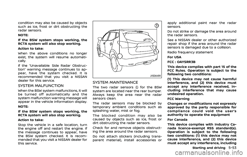
SYSTEM MAINTENANCE
The two radar sensorsfor the BSW
system are located near the rear bumper.
Always keep the area near the radar
sensors clean.
The radar sensors may be blocked by
temporary ambient conditions such as
splashing water, mist or fog.
The blocked condition may also be
caused by objects such as ice, frost or
dirt obstructing the radar sensors.
Check for and remove objects obstruct-
ing the area around the radar sensors.
Do not attach stickers (including trans-
parent material), install accessories or apply additional paint near the radar
sensors.
Do not strike or damage the area around
the radar sensors.
See a NISSAN dealer or other authorized
repair shop if the area around the radar
sensors is damaged due to a collision.
Radio frequency statement
For USA
FCC : OAYSRR3B
This device complies with part 15 of the
FCC Rules. Operation is subject to the
following two conditions:
(1) This device may not cause harmful
interference, and (2) this device must
accept any interference received, in-
cluding interference that may cause
undesired operation.
FCC Warning
Changes or modifications not expressly
approved by the party responsible for
compliance could void the user’s
authority to operate the equipment
For Canada
This device complies with Industry Ca-
nada licence-exempt RSS standard(s).
Operation is subject to the following
two conditions: (1) this device may not
cause interference, and (2) this device
must accept any interference, including
Starting and driving5-53
Page 301 of 508
caused by objects such as ice, frost or dirt
obstructing the radar sensors.
NOTE:
If the BSW system stops working, the
RCTA system will also stop working.
Action to take:
When the above conditions no longer
exist, the system will resume automati-
cally.
SYSTEM MALFUNCTION
When the RCTA system malfunctions, it
will turn off automatically. The system
malfunction warning message will appear
in the vehicle information display.
NOTE:
If the BSW system stops working, the
RCTA system will also stop working.
Action to take:
Stop the vehicle in a safe location, turn
the engine off and restart the engine. If
the message continues to appear, have
the system checked. It is recommended
that you visit a NISSAN dealer for this
service.
JVS0649X
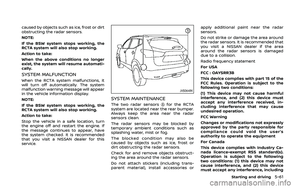
SYSTEM MAINTENANCE
The two radar sensorsfor the RCTA
system are located near the rear bumper.
Always keep the area near the radar
sensors clean.
The radar sensors may be blocked by
temporary ambient conditions such as
splashing water, mist or fog.
The blocked condition may also be
caused by objects such as ice, frost or
dirt obstructing the radar sensors.
Check for and remove objects obstruct-
ing the area around the radar sensors.
Do not attach stickers (including trans-
parent material), install accessories or apply additional paint near the radar
sensors.
Do not strike or damage the area around
the radar sensors. It is recommended that
you visit a NISSAN dealer if the area
around the radar sensors is damaged
due to a collision.
Radio frequency statement
For USA
FCC : OAYSRR3B
This device complies with part 15 of the
FCC Rules. Operation is subject to the
following two conditions:
(1) This device may not cause harmful
interference, and (2) this device must
accept any interference received, in-
cluding interference that may cause
undesired operation.
FCC Warning
Changes or modifications not expressly
approved by the party responsible for
compliance could void the user’s
authority to operate the equipment
For Canada
This device complies with Industry Ca-
nada licence-exempt RSS standard(s).
Operation is subject to the following
two conditions: (1) this device may not
cause interference, and (2) this device
must accept any interference, including
Starting and driving5-61
Page 315 of 508
HOW TO CANCEL THE PROPILOT
ASSIST SYSTEM
To cancel the ProPILOT assist system, use
one of the following methods:
.Push the CANCEL switch.
. Tap the brake pedal (except at a
standstill).
. Push the ProPILOT assist switch to
turn the system off. The ProPILOT
assist status indicator will turn off.
When the ProPILOT assist system is
canceled while the vehicle is stopped,
the electronic parking brake is automati-
cally activated.
WARNING
To prevent the vehicle from moving
or rolling unexpectedly, which could
result in serious personal injury or
property damage, before exiting the
vehicle make sure to push the Pro-
PILOT assist switch to turn the sys-
tem off, place the shift lever in the P
(Park) position, and turn the engine
off.
INTELLIGENT CRUISE CONTROL
(ICC)
WARNING
Failure to follow the warnings and
instructions for proper use of the ICC
system could result in serious injury
or death.
. The ICC system is only an aid to
assist the driver and is not a
collision warning or avoidance
device. It is recommended for
highway use only and it is not
intended for city driving. It is the
driver’s responsibility to stay
alert, drive safely, and be in con-
trol of the vehicle at all times.
. There are limitations to the ICC
system capability. The ICC system
does not function in all driving,
traffic, weather, and road condi-
tions. It is the driver’s responsi-
bility to stay alert, drive safely,
keep the vehicle in the traveling
lane, and be in control of the
vehicle at all times.
. Always observe posted speed
limits and do not set the speed
over them. .
The ICC system does not react to
stationary and slow moving vehi-
cles.
. Always drive carefully and atten-
tively when using the ICC system.
Read and understand the Owner’s
Manual thoroughly before using
the ICC system. To avoid serious
injury or death, do not rely on the
system to prevent accidents or to
control the vehicle’s speed in
emergency situations. Do not
use the ICC system except in
appropriate road and traffic con-
ditions.
ICC system operation
The ICC system is designed to maintain a
selected distance from the vehicle in front
of you and can reduce the speed to
match a slower vehicle ahead. The sys-
tem decelerates the vehicle as necessary
and if the vehicle ahead comes to a stop,
the vehicle decelerates to a standstill.
However, the ICC system can only apply
up to 40% of the vehicle’s total braking
power. This system should only be used
when traffic conditions allow vehicle
speeds to remain fairly constant or when
vehicle speeds change gradually. If a
vehicle moves into the traveling lane
Starting and driving5-75
Page 323 of 508
.Any door is open.
. The driver’s seat belt is not fastened.
. The vehicle ahead is not detected and
your vehicle is traveling below the
speed of 15 MPH (24 km/h).
. Your vehicle has been stopped by the
ICC system for approximately 3 min-
utes or longer.
. The shift lever is not in the D (Drive)
position or manual shift mode.
. The electronic parking brake is ap-
plied.
. The VDC system is turned off.
. The AEB applies harder braking
. VDC (including the traction control
system) operates.
. A wheel slips.
. When distance measurement be-
comes impaired due to adhesion of
dirt or obstruction to the sensor.
. When the radar signal is temporarily
interrupted.
Action to take:
When the conditions listed above are no
longer present, turn the system off using
the ProPILOT Assist switch. Turn the
ProPILOT Assist system back on to use
the system. NOTE:
When the ICC system is canceled under
the following conditions at a standstill,
the electronic parking brake is automa-
tically activated:
.
Any door is open.
. The driver’s seat belt is not fastened.
. Your vehicle has been stopped by
the ICC system for approximately 3
minutes or longer.
. The shift lever is not in the D (Drive)
position or manual shift mode.
. The VDC system is turned off.
. When distance measurement be-
comes impaired due to adhesion of
dirt or obstruction to the sensor.
. When the radar signal is temporarily
interrupted.
Condition B:
When the radar sensor of the front
bumper is covered with dirt or is ob-
structed, the ICC system will automati-
cally be canceled.
The chime will sound and the “Forward
Driving Aids Temporarily Disabled Front
Sensor Blocked” or “Unavailable: Front
Radar Obstruction” warning message will
appear in the vehicle information display. Action to take:
If the warning message appears, stop the
vehicle in a safe place, place the shift lever
in the P (Park) position, and turn the
engine off. When the radar signal is
temporarily interrupted, clean the sensor
area of the front bumper and restart the
engine. If the “Forward Driving Aids Tem-
porarily Disabled Front Sensor Blocked” or
“Unavailable: Front Radar Obstruction”
warning message continues to be dis-
played, have the system checked. It is
recommended that you visit a NISSAN
dealer for this service.
Condition C:
When driving on roads with limited road
structures or buildings (for example, long
bridges, deserts, snow fields, driving next
to long walls), the system may illuminate
the system warning light and display the
“Forward Driving Aids Temporarily Dis-
abled Front Sensor Blocked” or “Unavail-
able: Front Radar Obstruction” warning
message.
Action to take:
When the above driving conditions no
longer exist, turn the system back on.
Starting and driving5-83
Page 324 of 508

5-84Starting and driving
ICC system malfunction
If the ICC system malfunctions, it will be
turned off automatically, a chime will
sound, and the speed control status
warning (orange) will illuminate.
Action to take:
If the warning illuminates, stop the vehicle
in a safe place. Turn the engine off, restart
the engine and set the ICC system again.
If it is not possible to set the ICC system or
the warning stays on, it may be a
malfunction. Although the normal driving
can be continued, the ICC system should
be inspected. It is recommended that you
visit a NISSAN dealer for this service.
ICC sensor maintenance
The radar sensor is located on the front of
the vehicle.
To keep the ICC system operating prop-
erly, be sure to observe the following:
.Always keep the sensor area clean.
. Do not strike or damage the areas
around the sensor.
. Do not attach a sticker (including
transparent material) or install an
accessory near the sensor. This could
cause failure or malfunction.
. Do not attach metallic objects near
the sensor area (brush guard, etc.).
This could cause failure or malfunc- tion.
. Do not alter, remove, or paint the front
bumper.
Before customizing or restoring the front
bumper, it is recommended that you visit
a NISSAN dealer.
The camera sensor is located above the
inside mirror.
To keep the proper operation of the
systems and prevent a system malfunc-
tion, be sure to observe the following:
. Always keep the windshield clean.
. Do not attach a sticker (including
transparent material) or install an
accessory near the camera unit.
. Do not place reflective materials, such
as white paper or a mirror, on the
instrument panel. The reflection of
sunlight may adversely affect the
camera unit’s capability of detecting
the lane markers.
. Do not strike or damage the areas
around the camera unit. Do not touch
the camera lens or remove the screw
located on the camera unit.
If the camera unit is damaged due to an
accident, it is recommended that you visit
a NISSAN dealer.
STEERING ASSIST
WARNING
Failure to follow the warnings and
instructions for proper use of the
steering assist could result in serious
injury or death.
. The steering assist is not a repla-
cement for proper driving proce-
dures and is not designed to
correct careless, inattentive or
absent-minded driving. The
steering assist will not always
steer the vehicle to keep it in the
lane. It is not designed to prevent
loss of control. It is the driver’s
responsibility to stay alert, drive
safely, keep the vehicle in the
traveling lane, and be in control
of the vehicle at all times.
. As there is a performance limit to
the steering assist’s capability,
never rely solely on the system.
The steering assist does not func-
tion in all driving, traffic, weather,
and road conditions. Always drive
safely, pay attention to the op-
eration of the vehicle, and manu-
ally control your vehicle
appropriately.
Page 330 of 508

5-90Starting and driving
Action to take:
Stop the vehicle in a safe location, place
the shift lever in the P (Park) position, turn
the engine off, restart the engine, resume
driving, and set the ICC system again. If
the warning (orange) continues to illumi-
nate, the steering assist is malfunctioning.
Although the vehicle is still drivable under
normal conditions, have the system
checked. It is recommended that you visit
a NISSAN dealer for this service.
Steering assist maintenance
The camera is located above the inside
mirror.
To keep the proper operation of the
system and prevent a system malfunc-
tion, be sure to observe the following:
.Always keep the windshield clean.
. Do not attach a sticker (including
transparent material) or install an
accessory near the camera unit.
. Do not place reflective materials, such
as white paper or a mirror, on the
instrument panel. The reflection of
sunlight may adversely affect the
camera unit’s capability of detecting
the lane markers.
. Do not strike or damage the areas
around the camera unit. Do not touch
the camera lens or remove the screw
located on the camera unit. If the camera unit is damaged due to an
accident, it is recommendedthat you visit
a NISSAN dealer.
Radio frequency statement:
For USA
FCC ID OAYARS4B
This device complies with Part 15 of the
FCC Rules. Operation is subject to the
following two conditions:
1. This device may not cause harmful
interference, and
2. This device must accept any interfer- ence received, including interference
that may cause undesired operation.
FCC Warning
Changes or modifications not expressly
approved by the party responsible for
compliance could void the user’s author-
ity to operate the equipment.
For Canada
Model: ARS4–B
IC: 4135A-ARS4B
FCC ID: OAYARS4B
This device complies with Part 15 of the
FCC Rules and with Industry Canada
licence-exempt RSS standard(s). Opera-
tion is subject to the following two con-
ditions: 1. This device may not cause harmful
interference, and
2. This device must accept any interfer- ence received, including interference
that may cause undesired operation.
Le present appareil est conforme aux CNR
d’Industrie Canada applicables aux appa-
reils radio exempts de licence. L’exploita-
tion est autorisee aux deux conditions
suivantes:
1. L’appareil ne doit pas produire de brouillage, et
2. L’utilisateur de l’appareil doit accepter tout brouillage radioelectrique subi,
meme si le brouillage est susceptible
d’en compromettre le fonctionne-
ment.
Radio Frequency Radiation Exposure In-
formation:
This equipment complies with FCC radia-
tion exposure limits set forth for an
uncontrolled environment.
This equipment should be installed and
operated with minimum distance of 30
cm between the radiator and your body.
The transmitter must not be co-located
or operating in conjunction with any
other antenna or transmitter.
Cet equipement est conforme aux limites
d’exposition aux rayonnements IC eta-
Page 335 of 508
WAC0212X
INTELLIGENT DRIVER ALERTNESS (I-
DA) SYSTEM OPERATION
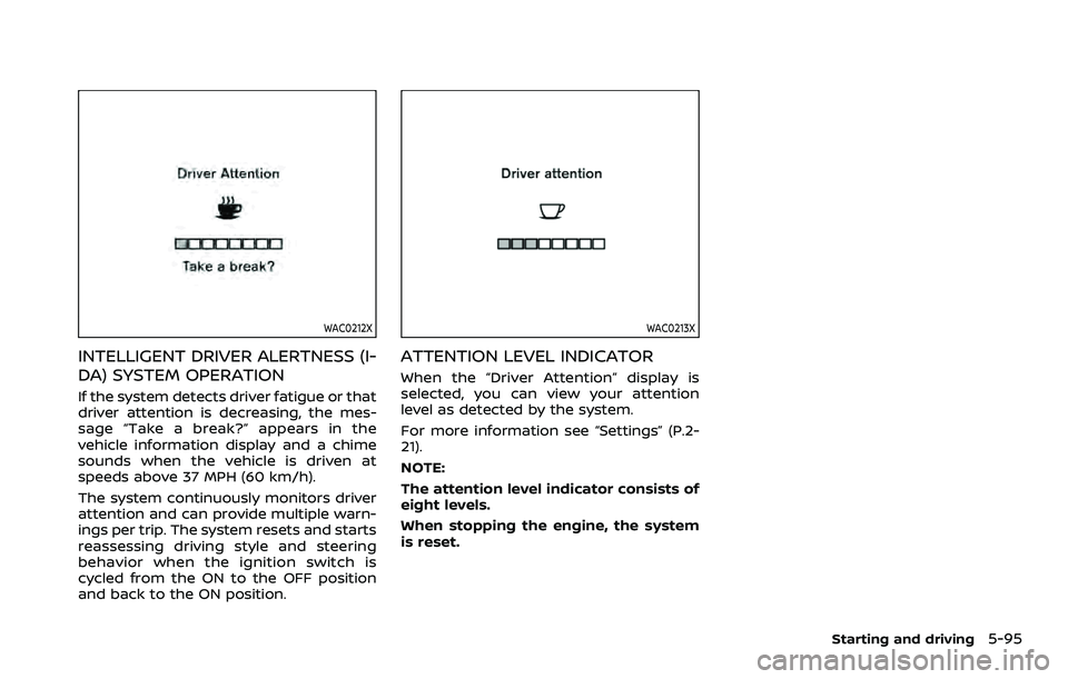
If the system detects driver fatigue or that
driver attention is decreasing, the mes-
sage “Take a break?” appears in the
vehicle information display and a chime
sounds when the vehicle is driven at
speeds above 37 MPH (60 km/h).
The system continuously monitors driver
attention and can provide multiple warn-
ings per trip. The system resets and starts
reassessing driving style and steering
behavior when the ignition switch is
cycled from the ON to the OFF position
and back to the ON position.
WAC0213X
ATTENTION LEVEL INDICATOR
When the “Driver Attention” display is
selected, you can view your attention
level as detected by the system.
For more information see “Settings” (P.2-
21).
NOTE:
The attention level indicator consists of
eight levels.
When stopping the engine, the system
is reset.
Starting and driving5-95