headlight NISSAN ROGUE SELECT 2015 2.G User Guide
[x] Cancel search | Manufacturer: NISSAN, Model Year: 2015, Model line: ROGUE SELECT, Model: NISSAN ROGUE SELECT 2015 2.GPages: 322, PDF Size: 2.21 MB
Page 107 of 322
2-32Instruments and controls
The power outlet is located in the instrument
panel and the center console.
CAUTION
.The outlet and plug may be hot
during or immediately after use.
. Do not use with accessories that
exceed a 12 volt, 120W (10A) power
draw. Do not use double adapters or
more than one electrical accessory.
. Use power outlet with the engine
running to avoid discharging the
vehicle battery.
. Avoid using power outlet when the
air conditioner, headlights or rear
window defroster is on.
. Before inserting or disconnecting a
plug, be sure the electrical acces-
sory being used is turned OFF.
. This power outlet is not designed
for use with a cigarette lighter unit.
. Push the plug in as far as it will go.
If good contact is not made, the plug
may overheat or the internal tem-
perature fuse may open. .
When not in use, be sure to close
the cap. Do not allow water or any
liquid to contact the outlet.
CUP HOLDERS
CAUTION
.Avoid abrupt starting and braking
when the cup holder is being used
to prevent spilling the drink. If the
liquid is hot, it can scald you or your
passenger.
. Use only soft cups in the cup holder.
Hard objects can injure you in an
accident.
STORAGE
Page 117 of 322
2-42Instruments and controls
CAUTION
Do not use for extended periods of time
with the engine stopped. This could
result in a discharged battery.
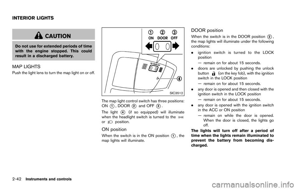
MAP LIGHTS
Push the light lens to turn the map light on or off.
SIC3512
The map light control switch has three positions:
ON
*1, DOOR*2and OFF*3.
The light
*4(if so equipped) will illuminate
when the headlight switch is turned to the
orposition.
ON position
When the switch is in the ON position*1, the
map lights will illuminate.
DOOR position
When the switch is in the DOOR position*2,
the map lights will illuminate under the following
conditions:
. ignition switch is turned to the LOCK
position
— remain on for about 15 seconds.
. doors are unlocked by pushing the unlock
button
(on the key fob) , with the ignition
switch in the LOCK position
— remain on for about 15 seconds.
. any door is opened and then closed with the
ignition switch in the LOCK position
— remain on for about 15 seconds.
. any door is opened with the ignition switch
in the ACC or ON position
— remain on while the door is opened.
When the door is closed, the lights go
off.
The lights will turn off after a period of
time when the lights remain illuminated to
prevent the battery from becoming dis-
charged.
INTERIOR LIGHTS
Page 126 of 322
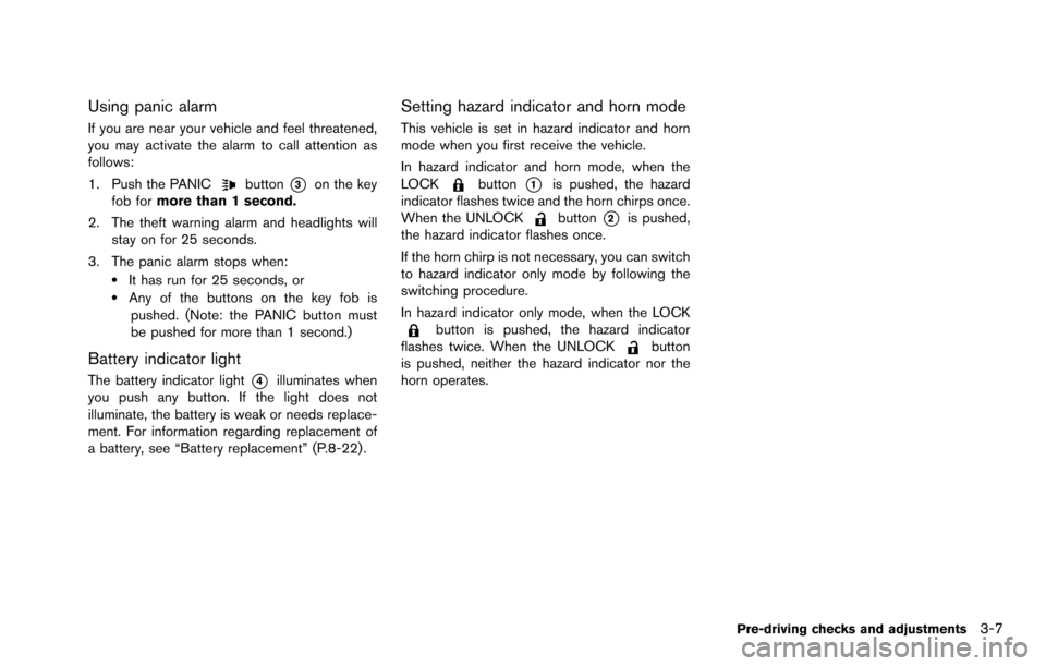
Using panic alarm
If you are near your vehicle and feel threatened,
you may activate the alarm to call attention as
follows:
1. Push the PANIC
button*3on the key
fob for more than 1 second.
2. The theft warning alarm and headlights will stay on for 25 seconds.
3. The panic alarm stops when:
.It has run for 25 seconds, or.Any of the buttons on the key fob is pushed. (Note: the PANIC button must
be pushed for more than 1 second.)
Battery indicator light
The battery indicator light*4illuminates when
you push any button. If the light does not
illuminate, the battery is weak or needs replace-
ment. For information regarding replacement of
a battery, see “Battery replacement” (P.8-22) .
Setting hazard indicator and horn mode
This vehicle is set in hazard indicator and horn
mode when you first receive the vehicle.
In hazard indicator and horn mode, when the
LOCK
button*1is pushed, the hazard
indicator flashes twice and the horn chirps once.
When the UNLOCK
button*2is pushed,
the hazard indicator flashes once.
If the horn chirp is not necessary, you can switch
to hazard indicator only mode by following the
switching procedure.
In hazard indicator only mode, when the LOCK
button is pushed, the hazard indicator
flashes twice. When the UNLOCKbutton
is pushed, neither the hazard indicator nor the
horn operates.
Pre-driving checks and adjustments3-7
Page 133 of 322
3-14Pre-driving checks and adjustments
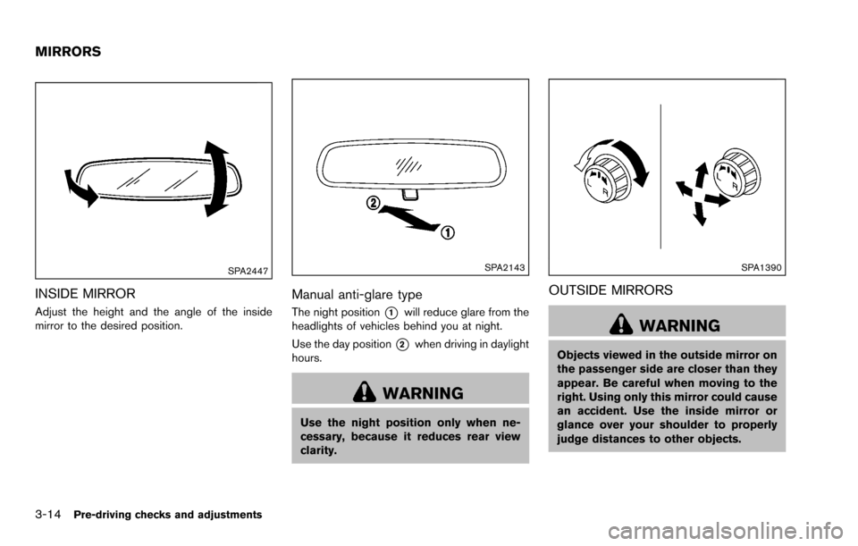
SPA2447
INSIDE MIRROR
Adjust the height and the angle of the inside
mirror to the desired position.
SPA2143
Manual anti-glare type
The night position*1will reduce glare from the
headlights of vehicles behind you at night.
Use the day position
*2when driving in daylight
hours.
WARNING
Use the night position only when ne-
cessary, because it reduces rear view
clarity.
SPA1390
OUTSIDE MIRRORS
WARNING
Objects viewed in the outside mirror on
the passenger side are closer than they
appear. Be careful when moving to the
right. Using only this mirror could cause
an accident. Use the inside mirror or
glance over your shoulder to properly
judge distances to other objects.
MIRRORS
Page 242 of 322
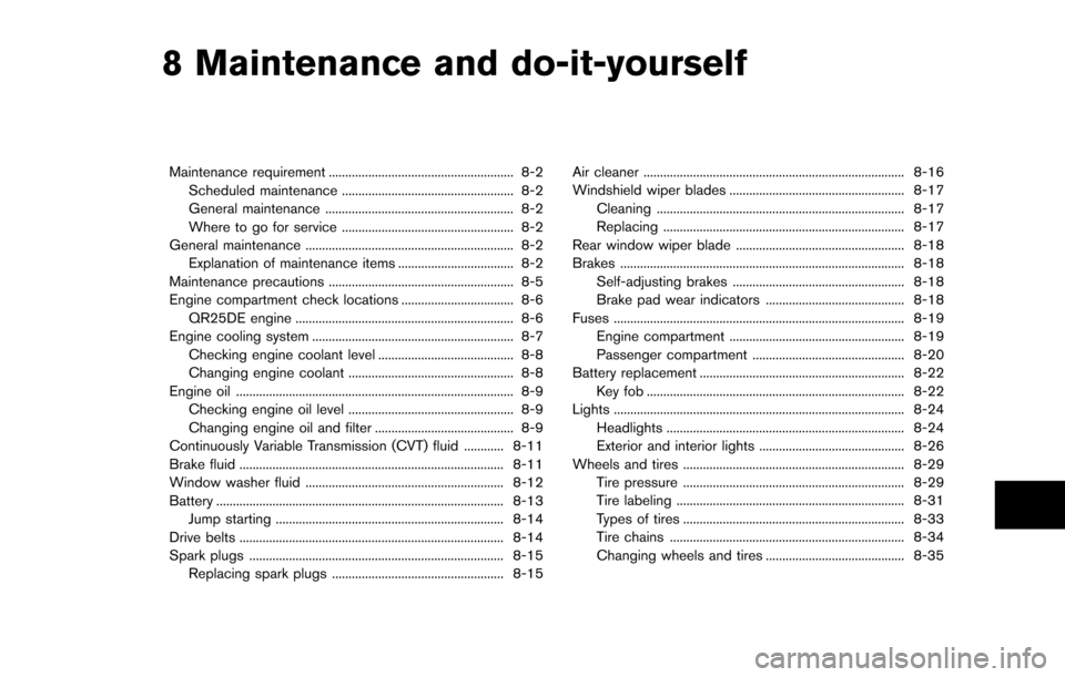
8 Maintenance and do-it-yourself
Maintenance requirement ........................................................ 8-2Scheduled maintenance .................................................... 8-2
General maintenance ......................................................... 8-2
Where to go for service .................................................... 8-2
General maintenance ............................................................... 8-2 Explanation of maintenance items ................................... 8-2
Maintenance precautions ........................................................ 8-5
Engine compartment check locations .................................. 8-6 QR25DE engine .................................................................. 8-6
Engine cooling system ............................................................. 8-7
Checking engine coolant level ......................................... 8-8
Changing engine coolant .................................................. 8-8
Engine oil ........................................................................\
............ 8-9
Checking engine oil level .................................................. 8-9
Changing engine oil and filter .......................................... 8-9
Continuously Variable Transmission (CVT) fluid ............ 8-11
Brake fluid ........................................................................\
........ 8-11
Window washer fluid ............................................................ 8-12
Battery ........................................................................\
............... 8-13 Jump starting ..................................................................... 8-14
Drive belts ........................................................................\
........ 8-14
Spark plugs ........................................................................\
..... 8-15 Replacing spark plugs .................................................... 8-15 Air cleaner ........................................................................\
....... 8-16
Windshield wiper blades ..................................................... 8-17
Cleaning ........................................................................\
... 8-17
Replacing ........................................................................\
. 8-17
Rear window wiper blade ................................................... 8-18
Brakes ........................................................................\
.............. 8-18
Self-adjusting brakes .................................................... 8-18
Brake pad wear indicators .......................................... 8-18
Fuses ........................................................................\
................ 8-19 Engine compartment ..................................................... 8-19
Passenger compartment .............................................. 8-20
Battery replacement .............................................................. 8-22 Key fob ........................................................................\
...... 8-22
Lights ........................................................................\
................ 8-24 Headlights ........................................................................\
8-24
Exterior and interior lights ............................................ 8-26
Wheels and tires ................................................................... 8-29 Tire pressure ................................................................... 8-29
Tire labeling ..................................................................... 8-31
Types of tires ................................................................... 8-33
Tire chains ....................................................................... 8-34
Changing wheels and tires .......................................... 8-35
Page 244 of 322
Lights*:Clean the headlights on a regular basis.
Make sure that the headlights, stop lights, tail
lights, turn signal lights, and other lights are all
operating properly and installed securely. Also
check headlight aim.
Road wheel nuts (lug nuts)*: When checking
the tires, make sure no wheel nuts are missing,
and check for any loose wheel nuts. Tighten if
necessary.
Tire rotation*: Tires should be rotated every
5,000 miles (8,000 km) .
Tires*: Check the pressure with a gauge often
and always prior to long distance trips. If
necessary, adjust the pressure in all tires,
including the spare, to the pressure specified.
Check carefully for damage, cuts or excessive
wear.
Tire Pressure Monitoring System (TPMS)
transmitter components: Replace the TPMS
transmitter grommet seal, valve core and cap
when the tires are replaced due to wear or age.
Wheel alignment and balance: If the vehicle
should pull to either side while driving on a
straight and level road, or if you detect uneven or
abnormal tire wear, there may be a need for
wheel alignment.
If the steering wheel or seat vibrates at normal
highway speeds, wheel balancing may be
needed. For additional information regarding tires, refer
to “Important Tire Safety Information” in the
Warranty Information Booklet.
Windshield:
Clean the windshield on a regular
basis. Check the windshield at least every six
months for cracks or other damage. Have a
damaged windshield repaired by a qualified
repair facility.
Windshield wiper blades*: Check for cracks
or wear if they do not wipe properly.
Inside the vehicle
The maintenance items listed here should be
checked on a regular basis, such as when
performing scheduled maintenance, cleaning
the vehicle, etc.
Accelerator pedal: Check the pedal for
smooth operation and make sure the pedal
does not catch or require uneven effort. Keep
the floor mat away from the pedal.
Brake pedal: Check the pedal for smooth
operation. If the brake pedal suddenly goes
down further than normal, the pedal feels
spongy or the vehicle seems to take longer to
stop, see a NISSAN dealer immediately. Keep
the floor mat away from the pedal.
Brakes: Check that the brakes do not pull the
vehicle to one side when applied. Continuously Variable Transmission (CVT)
P (Park) position mechanism:
On a fairly
steep hill, check that the vehicle is held securely
with the shift lever in the P (Park) position
without applying any brakes.
Parking brake: Check the parking brake
operation regularly. The vehicle should be
securely held on a fairly steep hill with only the
parking brake applied. If the parking brake needs
adjusted, see a NISSAN dealer.
Seat belts: Check that all parts of the seat belt
system (for example, buckles, anchors, adjusters
and retractors) operate properly and smoothly,
and are installed securely. Check the belt
webbing for cuts, fraying, wear or damage.
Seats: Check seat position controls such as
seat adjusters, seatback recliner, etc. to ensure
they operate smoothly and that all latches lock
securely in every position. Check that the head
restraints/headrests move up and down
smoothly and that the locks (if so equipped)
hold securely in all latched positions.
Steering wheel: Check for changes in the
steering conditions, such as excessive free play,
hard steering or strange noises.
Warning lights and chimes: Make sure that
all warning lights and chimes are operating
properly.
Maintenance and do-it-yourself8-3
Page 260 of 322
light to moderate stops is normal and does not
affect the function or performance of the brake
system.
Proper brake inspection intervals should
be followed.For additional information, see the
maintenance log section of your “NISSAN
Service and Maintenance Guide”.
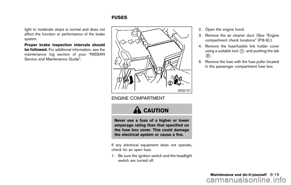
SDI2107
ENGINE COMPARTMENT
CAUTION
Never use a fuse of a higher or lower
amperage rating than that specified on
the fuse box cover. This could damage
the electrical system or cause a fire.
If any electrical equipment does not operate,
check for an open fuse.
1. Be sure the ignition switch and the headlight switch are turned off. 2. Open the engine hood.
3. Remove the air cleaner duct. (See “Engine
compartment check locations” (P.8-6) .)
4. Remove the fuse/fusible link holder cover using a suitable tool
*1and pushing the tab
*2.
5. Remove the fuse with the fuse puller located in the passenger compartment fuse box.
Maintenance and do-it-yourself8-19
FUSES
Page 261 of 322
8-20Maintenance and do-it-yourself
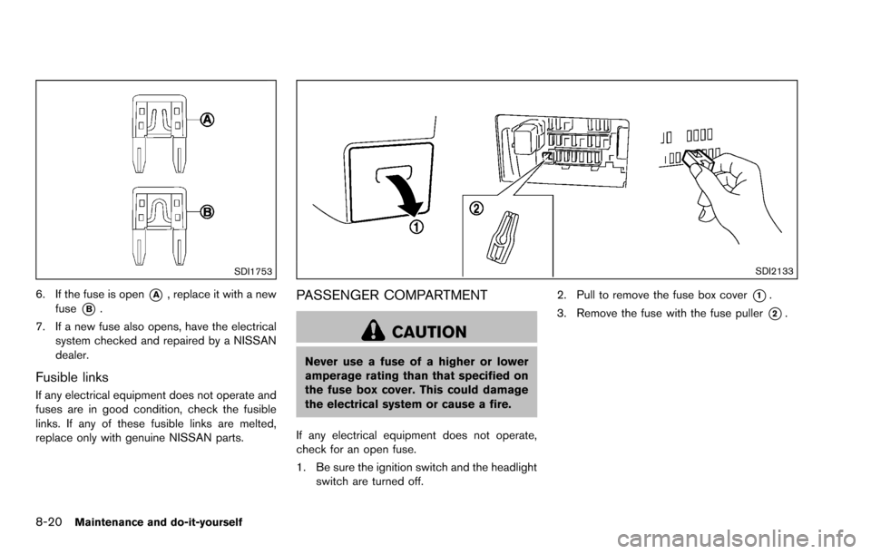
SDI1753
6. If the fuse is open*A, replace it with a new
fuse
*B.
7. If a new fuse also opens, have the electrical system checked and repaired by a NISSAN
dealer.
Fusible links
If any electrical equipment does not operate and
fuses are in good condition, check the fusible
links. If any of these fusible links are melted,
replace only with genuine NISSAN parts.
SDI2133
PASSENGER COMPARTMENT
CAUTION
Never use a fuse of a higher or lower
amperage rating than that specified on
the fuse box cover. This could damage
the electrical system or cause a fire.
If any electrical equipment does not operate,
check for an open fuse.
1. Be sure the ignition switch and the headlight switch are turned off. 2. Pull to remove the fuse box cover
*1.
3. Remove the fuse with the fuse puller
*2.
Page 262 of 322
SDI1753
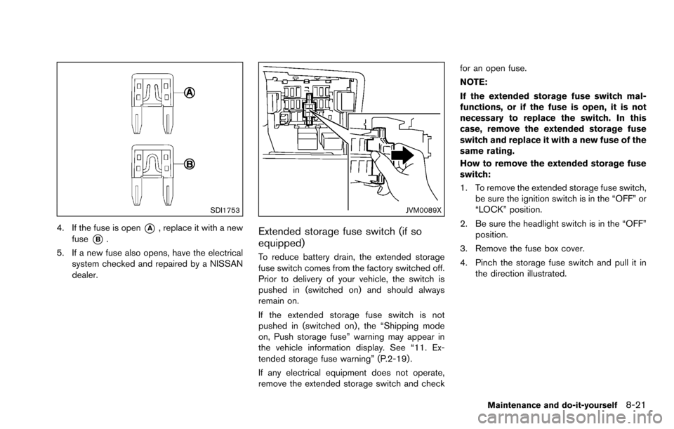
4. If the fuse is open*A, replace it with a new
fuse
*B.
5. If a new fuse also opens, have the electrical system checked and repaired by a NISSAN
dealer.
JVM0089X
Extended storage fuse switch (if so
equipped)
To reduce battery drain, the extended storage
fuse switch comes from the factory switched off.
Prior to delivery of your vehicle, the switch is
pushed in (switched on) and should always
remain on.
If the extended storage fuse switch is not
pushed in (switched on) , the “Shipping mode
on, Push storage fuse” warning may appear in
the vehicle information display. See “11. Ex-
tended storage fuse warning” (P.2-19) .
If any electrical equipment does not operate,
remove the extended storage switch and check for an open fuse.
NOTE:
If the extended storage fuse switch mal-
functions, or if the fuse is open, it is not
necessary to replace the switch. In this
case, remove the extended storage fuse
switch and replace it with a new fuse of the
same rating.
How to remove the extended storage fuse
switch:
1. To remove the extended storage fuse switch,
be sure the ignition switch is in the “OFF” or
“LOCK” position.
2. Be sure the headlight switch is in the “OFF” position.
3. Remove the fuse box cover.
4. Pinch the storage fuse switch and pull it in the direction illustrated.
Maintenance and do-it-yourself8-21
Page 265 of 322
8-24Maintenance and do-it-yourself
JVM0520X
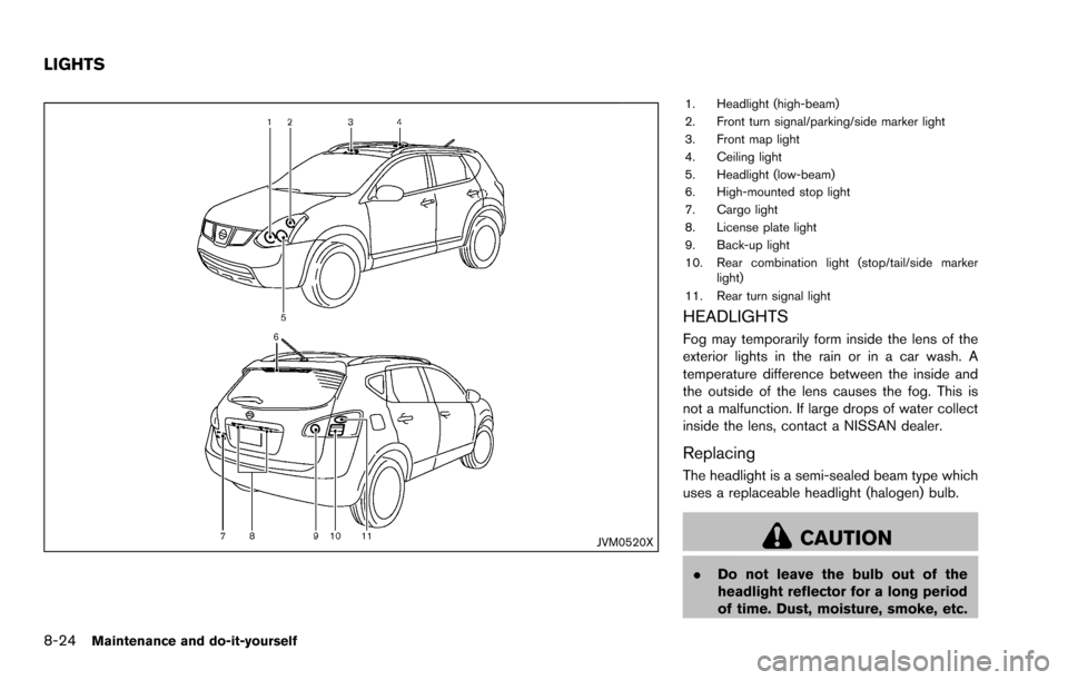
1. Headlight (high-beam)
2. Front turn signal/parking/side marker light
3. Front map light
4. Ceiling light
5. Headlight (low-beam)
6. High-mounted stop light
7. Cargo light
8. License plate light
9. Back-up light
10. Rear combination light (stop/tail/side markerlight)
11. Rear turn signal light
HEADLIGHTS
Fog may temporarily form inside the lens of the
exterior lights in the rain or in a car wash. A
temperature difference between the inside and
the outside of the lens causes the fog. This is
not a malfunction. If large drops of water collect
inside the lens, contact a NISSAN dealer.
Replacing
The headlight is a semi-sealed beam type which
uses a replaceable headlight (halogen) bulb.
CAUTION
. Do not leave the bulb out of the
headlight reflector for a long period
of time. Dust, moisture, smoke, etc.
LIGHTS