battery replacement NISSAN ROGUE SPORT 2018 Owners Manual
[x] Cancel search | Manufacturer: NISSAN, Model Year: 2018, Model line: ROGUE SPORT, Model: NISSAN ROGUE SPORT 2018Pages: 512, PDF Size: 3.33 MB
Page 105 of 512

2-28Instruments and controls
VEHICLE INFORMATION DISPLAY
WARNINGS AND INDICATORS
1. Engine start operation indicator
(for Continuously Variable Trans-
mission (CVT) models)
This indicator appears when the shift
lever is in the P (Park) position.
This indicator means that the engine will
start by pushing the ignition switch with
the brake pedal depressed. You can start
the engine directly in any position of the
ignition switch.
2. Engine start operation indicator
(for Manual Transmission (MT)
models)
This indicator means that the engine will
start by pushing the ignition switch with
the clutch pedal depressed. You can start
the engine directly in any position of the
ignition switch.
You can also start the engine by pushing
the ignition switch with the brake pedal
depressed when the shift lever is in the N
(Neutral) position.
3. No Key detected warning (if so
equipped)
This warning appears when the door is
closed with the Intelligent Key left outside
the vehicle and the ignition switch in the
ON position. Make sure that the Intelligent
Key is inside the vehicle.
See “Intelligent Key system” (P.3-11) for
more details.
4. Shift to Park warning (CVT mod-
els) (if so equipped)
This warning appears when the ignition
switch is pushed to stop the engine with
the shift lever in any position except the P
(Park) position.
If this warning appears, move the shift
lever to the P (Park) position or place the
ignition switch in the ON position.
An inside warning chime will also sound.
(See “Intelligent Key system” (P.3-11).)
5. Key battery low warning (if so
equipped)
This warning appears when the Intelli-
gent Key battery is running out of power.
If this indicator appears, replace the
battery with a new one. See “Intelligent
Key battery replacement” (P.8-23).
6. Engine start operation for Intelli-
gent Key system indicator (if so
equipped)
This indicator appears when the Intelli-
gent Key battery is running out of power
and when the Intelligent Key system and
vehicle are not communicating normally.
If this indicator appears, touch the igni-
tion switch with the Intelligent Key while
depressing the brake pedal. (See “Intelli-
gent Key battery discharge” (P.5-17).)
7. Key ID incorrect warning (if so
equipped)
This warning appears when the ignition
switch is placed from the LOCK position
and the Intelligent Key cannot be recog-
nized by the system. You cannot start the
engine with an unregistered key. Use the
registered Intelligent Key.
See “Intelligent Key system” (P.3-11).
8. Release Parking Brake warning
This warning appears when the vehicle
speed is above 4 MPH (7 km/h) (models
not equipped with electronic parking
brake) or 2 MPH (4 km/h) (models
equipped with electronic parking brake)
and the parking brake is applied. Stop the
vehicle and release the parking brake.
Page 153 of 512
3-8Pre-driving checks and adjustments
It is possible to lock/unlock all doors
(including the liftgate), and activate the
panic alarm by using the key fob from
outside the vehicle.
Before locking the doors, make sure the
key is not left in the vehicle.
The key fob can operate at a distance of
approximately 33 ft (10 m) from the
vehicle. (The effective distance depends
upon the conditions around the vehicle.)
As many as 4 key fobs can be used with
one vehicle. For information concerning
the purchase and use of additional key
fobs, contact a NISSAN dealer.
The key fob will not function:
.When the key fob is not within the
operational range.
. When the doors are open or not
closed securely.
. When the key is in the ignition switch.
. When the battery is discharged.
WARNING
The remote keyless entry key fob
transmits radio waves when the
buttons are pushed. The FAA advises
that the radio waves may affect
aircraft navigation and communica-
tion systems. Do not operate the key fob while on an airplane. Make sure
the buttons are not operated unin-
tentionally when the unit is stored
during a flight.
CAUTION
The following conditions or occur-
rences will damage the key fob.
.
Do not allow the key fob to
become wet.
. Do not drop the key fob.
. Do not strike the key fob sharply
against another object.
. If the outside temperature is be-
low 14°F (-10°C) degrees, the bat-
tery of key fob may not function
properly.
. Do not place the key fob for an
extended period in an area where
temperatures exceed 140°F
(60°C).
If a key fob is lost or stolen, NISSAN
recommends erasing the ID code of
that key fob. This will prevent the key
fob from unauthorized use to unlock
the vehicle. For information regard-
ing the erasing procedure, it is re-
commended that you visit a NISSAN dealer.
For information regarding the replace-
ment of a battery, see “Key fob battery
replacement” (P.8-21).
REMOTE KEYLESS ENTRY SYSTEM
(if so equipped)
Page 155 of 512

3-10Pre-driving checks and adjustments
.Any of the buttons on the key fob ispushed. (Note: the PANIC button
must be pushed for more than 1
second.)
Battery indicator light
The battery indicator lightilluminates
when you push any button. If the light
does not illuminate, the battery is weak or
needs replacement. For information re-
garding replacement of a battery, see
“Key fob battery replacement” (P.8-21).
Setting hazard indicator and horn
mode
This vehicle is set in hazard indicator and
horn mode when you first receive the
vehicle.
In hazard indicator and horn mode, when
the LOCK
buttonis pushed, the
hazard indicator flashes twice and the
horn chirps once. When the UNLOCK
buttonis pushed, the hazard indicator
flashes once.
If the horn chirp is not necessary, you can
switch to hazard indicator only mode by
following the switching procedure.
In hazard indicator only mode, when the
LOCK
button is pushed, the hazard
indicator flashes twice. When the UNLOCK
button is pushed, neither the hazard
indicator nor the horn operates.
Mode (Pushing theorbutton) DOOR LOCK
DOOR UNLOCK
Hazard indicator and horn mode HAZARD -
twice
HORN - once HAZARD -
once
HORN - none
Hazard indicator mode HAZARD - twiceHAZARD - none
Page 157 of 512
3-12Pre-driving checks and adjustments
.When the vehicle is parked near a
parking meter.
In such cases, correct the operating
conditions before using the Intelligent
Key function or use the mechanical key.
Although the life of the battery varies
depending on the operating conditions,
the battery’s life is approximately 2 years.
If the battery is discharged, replace it with
a new one.
Since the Intelligent Key is continuously
receiving radio waves, if the key is left
near equipment which transmits strong
radio waves, such as signals from a TV
and personal computer, the battery life
may become shorter.
For information regarding replacement of
a battery, see “Intelligent Key battery
replacement” (P.8-23).
As many as 4 Intelligent Keys can be
registered and used with one vehicle. For
information about the purchase and use
of additional Intelligent Keys, it is recom-
mended that you contact a NISSAN deal-
er.
CAUTION
. Do not allow the Intelligent Key,
which contains electrical compo-
nents, to come into contact with water or salt water. This could
affect the system function.
. Do not drop the Intelligent Key.
. Do not strike the Intelligent Key
sharply against another object.
. Do not change or modify the
Intelligent Key.
. Wetting may damage the Intelli-
gent Key. If the Intelligent Key
gets wet, immediately wipe until
it is completely dry.
. If the outside temperature is be-
low 14°F (−10°C) degrees, the bat-
tery of the Intelligent Key may not
function properly.
. Do not place the Intelligent Key
for an extended period in an area
where temperatures exceed
140°F (60°C).
. Do not attach the Intelligent Key
with a key holder that contains a
magnet.
. Do not place the Intelligent Key
near equipment that produces a
magnetic field, such as a TV,
audio equipment, personal com-
puters or cellular phone.
If an Intelligent Key is lost or stolen,
NISSAN recommends erasing the ID code of that Intelligent Key from the vehicle.
This may prevent the unauthorized use of
the Intelligent Key to operate the vehicle.
For information regarding the erasing
procedure, it is recommended that you
contact a NISSAN dealer.
The Intelligent Key function can be dis-
abled. For information about disabling
the Intelligent Key function, it is recom-
mended that you contact a NISSAN deal-
er.
Page 302 of 512

JVS0404X
INTELLIGENT KEY BATTERY DIS-
CHARGE
If the battery of the Intelligent Key is
discharged, or environmental conditions
interfere with the Intelligent Key opera-
tion, start the engine according to the
following procedure:
1. Move the shift lever to the P (Park)position (for CVT models) or the shift
lever to the N (Neutral) position (for MT
models).
2. Firmly apply the foot brake.
3. Touch the ignition switch with the Intelligent Key as illustrated. (A chime
will sound.) 4. Push the ignition switch while depres-
sing the brake pedal within 10 sec-
onds after the chime sounds. The
engine will start.
After step 3 is performed, when the
ignition switch is pushed without depres-
sing the brake pedal, the ignition switch
position will change to ACC.
NOTE:
. When the ignition switch is pushed
to the ON position or the engine is
started by the above procedures, the
“Key Battery Low” warning appears
(on the Vehicle information display)
even if the Intelligent Key is inside
the vehicle. This is not a malfunction.
To turn off the warning, touch the
ignition switch with the Intelligent
Key again.
. If the “Key Battery Low” warning
appears (on the Vehicle information
display), replace the battery as soon
as possible. (See “Intelligent Key
battery replacement” (P.8-23).) .
Make sure the area around the vehicle
is clear.
. Check fluid levels such as engine oil,
coolant, brake fluid, and window
washer fluid as frequently as possible,
or at least whenever you refuel.
. Check that all windows and lights are
clean.
. Visually inspect tires for their appear-
ance and condition. Also check tires
for proper inflation.
. Lock all doors.
. Position seat and adjust head re-
straints.
. Adjust inside and outside mirrors.
. Fasten seat belts and ask all passen-
gers to do likewise.
. Check the operation of warning lights
when the ignition switch is placed in
the ON position. (See “Warning lights,
indicator lights and audible remin-
ders” (P.2-10).)
Starting and driving5-17
BEFORE STARTING THE ENGINE
Page 426 of 512

8 Do-it-yourself
Maintenance precautions ...................................................... 8-2
Engine compartment check locations ........................ 8-3MR20DD engine model ..................................................... 8-4
Engine cooling system ............................................................. 8-4 Checking engine coolant level .................................... 8-5
Changing engine coolant ................................................ 8-6
Engine oil ........................................................................\
..................... 8-6 Checking engine oil level ................................................. 8-6
Changing engine oil and filter ..................................... 8-6
Continuously Variable Transmission
(CVT) fluid ........................................................................\
.................... 8-9
Brake and clutch (if so equipped) fluid ....................... 8-9
Window washer fluid .............................................................. 8-10
Battery ........................................................................\
........................ 8-11 Jump starting ........................................................................\
. 8-12
Variable voltage control system ................................... 8-13
Drive belt ........................................................................\
.................. 8-13
Spark plugs ........................................................................\
............. 8-14 Replacing spark plugs ..................................................... 8-14
Air cleaner ........................................................................\
............... 8-15 Windshield wiper blades ..................................................... 8-16
Cleaning ........................................................................\
........... 8-16
Replacing ........................................................................\
........ 8-16
Rear window wiper blade .................................................. 8-17
Brakes ........................................................................\
........................ 8-17 Self-adjusting brakes ..................................................... 8-17
Brake pad wear warning ............................................ 8-17
Fuses ........................................................................\
........................... 8-18 Engine compartment .................................................... 8-18
Passenger compartment ........................................... 8-20
Key fob battery replacement .......................................... 8-21
Intelligent Key battery replacement .......................... 8-23
Lights ........................................................................\
.......................... 8-25 Headlights ........................................................................\
...... 8-25
Exterior and interior lights ........................................ 8-27
Wheels and tires ........................................................................\
8-29
Tire pressure ........................................................................\
8-29
Tire labeling ........................................................................\
.. 8-33
Types of tires ....................................................................... 8-35
Tire chains ........................................................................\
...... 8-36
Changing wheels and tires ...................................... 8-37
Page 446 of 512
JVM0415X
Extended storage fuse switch (if so
equipped)
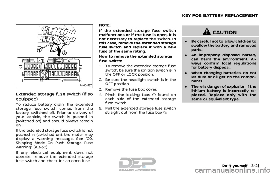
To reduce battery drain, the extended
storage fuse switch comes from the
factory switched off. Prior to delivery of
your vehicle, the switch is pushed in
(switched on) and should always remain
on.
If the extended storage fuse switch is not
pushed in (switched on), the meter may
display a warning message. See “20.
Shipping Mode On Push Storage Fuse
warning” (P.2-30).
If any electrical equipment does not
operate, remove the extended storage
fuse switch and check for an open fuse.NOTE:
If the extended storage fuse switch
malfunctions or if the fuse is open, it is
not necessary to replace the switch. In
this case, remove the extended storage
fuse switch and replace it with a new
fuse of the same rating.
How to remove the extended storage
fuse switch:
1. To remove the extended storage fuse
switch, be sure the ignition switch is in
the OFF or LOCK position.
2. Be sure the headlight switch is in the OFF position.
3. Remove the fuse box cover.
4. Pinch the locking tabs
found on
each side of the extended storage
fuse switch.
5. Pull the extended storage fuse switch straight out from the fuse box
.
CAUTION
.Be careful not to allow children to
swallow the battery and removed
parts.
. An improperly disposed battery
can harm the environment. Al-
ways confirm local regulations
for battery disposal.
. When changing batteries, do not
let dust or oil get on the compo-
nents.
. There is danger of explosion if the
lithium battery is incorrectly re-
placed. Replace only with the
same or equivalent type.
Do-it-yourself8-21
KEY FOB BATTERY REPLACEMENT
Page 447 of 512

8-22Do-it-yourself
JVM0381X
To replace the battery:
1. Insert a small screwdriver into the slit
to open the lid. Use a cloth to
protect the casing.
2. Replace the battery with a new one. Recommended battery: CR2032 or
equivalent
.Do not touch the internal circuitand electric terminals as doing so
could cause a malfunction.
.Hold the battery by the edges.Holding the battery across the
contact points will seriously deplete
the storage capacity.
.Make sure that the +side faces the
bottom of the case.
3. Close the lid securely.
4. Operate the buttons to check its operation.
See a NISSAN dealer if you need assis-
tance for replacement.
FCC Notice:
For USA:
This device complies with Part 15 of the
FCC Rules. Operation is subject to the
following two conditions: (1) This device
may not cause harmful interference,
and (2) this device must accept any
interference received, including inter-
ference that may cause undesired op-
eration.
Note: Changes or modifications not
expressly approved by the party re-
sponsible for compliance could void
the user’s authority to operate the
equipment. For Canada:
This device complies with Industry Ca-
nada licence-exempt RSS standard(s).
Operation is subject to the following
two conditions: (1) this device may not
cause interference, and (2) this device
must accept any interference, including
interference that may cause undesired
operation of the device.
Page 448 of 512
CAUTION
.Be careful not to allow children to
swallow the battery and removed
parts.
. An improperly disposed battery
can harm the environment. Al-
ways confirm local regulations
for battery disposal.
. When changing batteries, do not
let dust or oil get on the compo-
nents.
. There is danger of explosion if the
lithium battery is incorrectly re-
placed. Replace only with the
same or equivalent type.
SDI2451
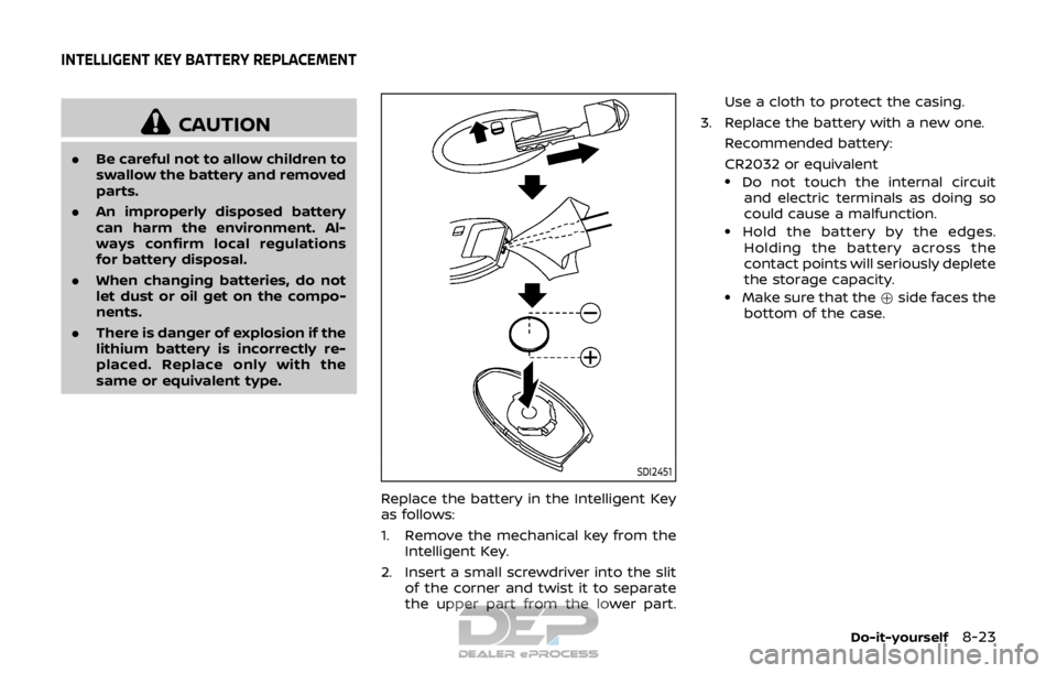
Replace the battery in the Intelligent Key
as follows:
1. Remove the mechanical key from the
Intelligent Key.
2. Insert a small screwdriver into the slit of the corner and twist it to separate
the upper part from the lower part. Use a cloth to protect the casing.
3. Replace the battery with a new one. Recommended battery:
CR2032 or equivalent
.Do not touch the internal circuitand electric terminals as doing so
could cause a malfunction.
.Hold the battery by the edges.
Holding the battery across the
contact points will seriously deplete
the storage capacity.
.Make sure that the +side faces the
bottom of the case.
Do-it-yourself8-23
INTELLIGENT KEY BATTERY REPLACEMENT
Page 451 of 512
8-26Do-it-yourself
Replacing
LED headlight model:
If LED headlight replacement is required,
it is recommended that you visit a NISSAN
dealer for this service.
Halogen headlight model:
The headlight is a semi-sealed beam type
which uses a replaceable headlight (halo-
gen) bulb.
CAUTION
.Do not leave the bulb out of the
headlight reflector for a long
period of time. Dust, moisture,
smoke, etc. entering the head-
light body may affect bulb per-
formance.
. High pressure halogen gas is
sealed inside the halogen bulb.
The bulb may break if the glass
envelope is scratched or the bulb
is dropped.
. Only touch the base when hand-
ling the bulb. Never touch the
glass envelope. Touching the
glass envelope could significantly
affect bulb life and/or headlight
performance. .
Aiming is not necessary after
replacing the bulb. When aiming
adjustment is necessary, it is
recommended you visit a NISSAN
dealer for this service.
Use the same number and wattage as
originally installed as shown in the chart.
JVM0395X
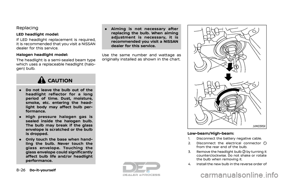
Low-beam/High-beam:
1. Disconnect the battery negative cable.
2. Disconnect the electrical connector
from the rear end of the bulb.
3. Remove the headlight bulb
by turning it
counterclockwise. Do not shake or rotate
the bulb when removing it.
4. Install the new bulb in the reverse order of