ESP NISSAN ROGUE SPORT 2019 Owners Manual
[x] Cancel search | Manufacturer: NISSAN, Model Year: 2019, Model line: ROGUE SPORT, Model: NISSAN ROGUE SPORT 2019Pages: 500, PDF Size: 2.37 MB
Page 38 of 500
1-18Safety — Seats, seat belts and supplemental restraint system
There are three basic types of child
restraint systems:
.Rear-facing child restraint
. Forward-facing child restraint
. Booster seat
The proper restraint depends on the
child’s size. Generally, infants up to about
1 year and less than 20 lbs (9 kg) should
be placed in rear-facing child restraints.
Forward-facing child restraints are avail-
able for children who outgrow rear-facing
child restraints and are at least 1 year old.
Booster seats are used to help position a
vehicle lap/shoulder belt on a child who
can no longer use a forward-facing child
restraint.
WARNING
Infants and children need special
protection. The vehicle’s seat belts
may not fit them properly. The
shoulder belt may come too close
to the face or neck. The lap belt may
not fit over their small hip bones. In
an accident, an improperly fitting
seat belt could cause serious or fatal
injury. Always use appropriate child
restraints.
All U.S. states and Canadian provinces or territories require the use of approved
child restraints for infants and small
children. See “Child restraints” (P.1-20).
A child restraint may be secured in the
vehicle by using either the LATCH (Lower
Anchors and Tethers for CHildren) system
or with the vehicle seat belt. See “Child
restraints” (P.1-20) for more information.
NISSAN recommends that all pre-teens
and children be restrained in the rear
seat. Studies show that children are
safer when properly restrained in the
rear seat than in the front seat.
This is especially important because
your vehicle has a supplemental re-
straint system (Air bag system) for the
front passenger. See “Supplemental
Restraint System (SRS)” (P.1-40).
INFANTS
Infants up to at least 1 year old should be
placed in a rear-facing child restraint.
NISSAN recommends that infants be
placed in child restraints that comply with
Federal Motor Vehicle Safety Standards
or Canadian Motor Vehicle Safety Stan-
dards. You should choose a child restraint
that fits your vehicle and always follow
the manufacturer’s instructions for instal-
lation and use.
SMALL CHILDREN
Children that are over 1 year old and
weigh at least 20 lbs (9 kg) should remain
in a rear-facing child restraint as long as
possible up to the height or weight limit
of the child restraint. Children who out-
grow the height or weight limit of the
rear-facing child restraint and are at least
1 year old should be secured in a forward-
facing child restraint with a harness. Refer
to the manufacturer’s instructions for
minimum and maximum weight and
height recommendations. NISSAN recom-
mends that small children be placed in
child restraints that comply with Federal
Motor Vehicle Safety Standards or Cana-
dian Motor Vehicle Safety Standards. You
should choose a child restraint that fits
your vehicle and always follow the man-
ufacturer’s instructions for installation
and use.
LARGER CHILDREN
Children should remain in a forward-
facing child restraint with a harness until
they reach the maximum height or
weight limit allowed by the child restraint
manufacturer.
Once a child outgrows the height or
weight limit of the harness-equipped
forward-facing child restraint, NISSAN
recommends that the child be placed in
a commercially available booster seat to
Page 65 of 500
.The curtain air bags ordinarily will
not inflate in the event of a front
impact, rear impact, or lower
severity side collision. Always
wear your seat belts to help
reduce the risk or severity of
injury in various kinds of acci-
dents.
. The seat belts, the side air bags
and curtain air bags are most
effective when you are sitting
well back and upright in the seat.
The side air bags and curtain air
bags inflate with great force. Do
not allow anyone to place their
hand, leg or face near the side air
bags on the side of the seatback
of the front seat or near the side
roof rails. Do not allow anyone
sitting in the front seats or rear
outboard seats to extend their
hand out of the window or lean
against the door. Some examples
of dangerous riding positions are
shown in the previous illustra-
tions.
. When sitting in the rear seat, do
not hold onto the seatback of the
front seat. If the side air bag
inflates, you may be seriously
injured. Be especially careful with
children, who should always be properly restrained. Some exam-
ples of dangerous riding posi-
tions are shown in the
illustrations.
. Do not use seat covers on the
front seatbacks. They may inter-
fere with side air bag inflation.
Safety — Seats, seat belts and supplemental restraint system1-45
Page 92 of 500
2-12Instruments and controls
gerous.
. Pressing the brake pedal with the
engine stopped and/or low brake
fluid level may increase your
stopping distance and braking
will require greater pedal effort
as well as pedal travel.
. If the brake fluid level is below the
minimum or MIN mark on the
brake fluid reservoir, do not drive
until the brake system has been
checked. It is recommended you
visit a NISSAN dealer for this
service.
Charge warning light
If the light illuminates while the engine is
running, it may indicate the charging
system is not functioning properly. Turn
the engine off and check the alternator
belt. If the belt is loose, broken, missing or
if the light remains on, have your vehicle
serviced immediately. It is recommended
you visit a NISSAN dealer for this service.
CAUTION
Do not continue driving if the alter-
nator belt is loose, broken or miss- ing.
Electric power steering warn-
ing light
When the ignition switch is in the ON
position, the electric power steering
warning light illuminates. After starting
the engine, the electric power steering
warning light turns off. This indicates the
electric power steering is operational.
If the electric power steering warning
light illuminates while the engine is run-
ning, it may indicate the electric power
steering is not functioning properly and
may need servicing. Have the system
checked. It is recommended that you visit
a NISSAN dealer for this service.
When the electric power steering warning
light illuminates with the engine running,
the power assist to the steering will cease
operation but you will still have control of
the vehicle. At this time, greater steering
efforts are required to operate the steer-
ing wheel, especially in sharp turns and at
low speeds.
(See “Electric power steering” (P.5-144).)
Electronic parking brake
warning light (yellow) (if so
equipped)
The electronic parking brake warning
light functions for the electronic parking
brake system. When the ignition switch is
placed in the ON position, the light
illuminates for a few seconds. If the
warning light illuminates at any other
time, it may indicate that the electronic
parking brake system is not functioning
properly. Have the brake system checked,
and, if necessary, repaired. It is recom-
mended that you visit a NISSAN dealer for
this service.
Automatic Emergency Braking
(AEB) system warning light
When the ignition switch is in the ON
position, the AEB system warning light
illuminates. After starting the engine, the
warning light turns off.
This light illuminates when the AEB sys-
tem is set to OFF on the vehicle informa-
tion display.
If the light illuminates when the AEB
system is ON, it may indicate that the
system is unavailable. See “Automatic
Emergency Braking (AEB)” (P.5-115) or
“Automatic Emergency Braking (AEB) with
Page 104 of 500
2-24Instruments and controls
“Lighting” menu, select “Light Sensitiv-
ity”. Use thebuttonsand the OKto select the required sensitivity.
The following options are available:
— Turn on earliest
— Turn on earlier
— Turn on standard
— Turn on later
. Light Off Delay (if so equipped)
The duration of the automatic head-
lights can be changed from 0 to 180
seconds. From the “Lighting” menu,
select “Light Off Delay”. Use the OK
to change the duration.
Turn indicator:
The “3 Flash Pass” overtaking feature can
be set to be ON or OFF. From the “Turn
indicator” menu, select “3 Flash Pass”. Use
the OK
to turn this feature ON or OFF.
Locking:
There are the following options in the
“Locking” menu:
. I–Key Door Lock (if so equipped)
When this item is turned on, the
request switch on the door is acti-
vated. From the “Locking” menu, select
“I-Key Door Lock”. Use the OK
to
activate or deactivate this function. .
Selective Unlock
When this item is turned on, and the
door handle request switch on the
driver’s or front passenger’s side door
is pushed, only the corresponding
door is unlocked. All the doors can
be unlocked if the door handle re-
quest switch is pushed again within 1
minute. When this item is turned to off,
all the doors will be unlocked when
the door handle request switch is
pushed once. From the “Locking”
menu, select “Selective Unlock”. Use
the OK
to activate or deactivate this
function.
. Auto Door Unlock
The “Auto Door Unlock” feature allows
the customer to customize the auto
door unlock options.
— Ignition OFF
— Shift to Park (for Continuously Vari-
able Transmission (CVT) models)
— Off
. Answer Bk. Horn (if so equipped)
When the answer back horn is on, the
horn will chirp and the hazard indica-
tors will flash twice when locking the
vehicle with the Intelligent Key or
remote keyless entry function. Wipers:
.
Speed Dependent
The “Speed Dependent” feature can be
activated or deactivated. From the
“Wipers” menu, select “Speed Depen-
dent”. Use the OK
to turn this
feature ON or OFF.
. Reverse Link
The “Reverse Link” wiper feature can
be set to be ON or OFF. From the
“Wipers” menu, select “Reverse Link”.
Use the OK
to turn this feature ON
or OFF.
. Drip wipe
The “Drip wipe” feature can be set to
be ON or OFF. From the “Wipers” menu,
select “Drip wipe”. Use the OK
to turn
this feature ON or OFF.
Rear Door Alert:
. Horn & Alert
When selected, the alert is displayed
and the horn sounds.
. Alert Only
When selected, only the alert is dis-
played.
. OFF
When selected, no alert or horn will be
active.
For additional information, refer to “Rear
door alert” (P.2-58).
Page 147 of 500
JVI1335X
CAUTION
Make sure the parcel shelf is care-
fully stored when not in use in order
to prevent any damage.
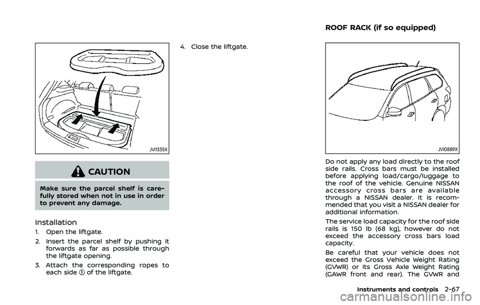
Installation
1. Open the liftgate.
2. Insert the parcel shelf by pushing itforwards as far as possible through
the liftgate opening.
3. Attach the corresponding ropes to each side
of the liftgate. 4. Close the liftgate.
JVI0889X
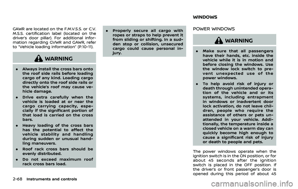
Do not apply any load directly to the roof
side rails. Cross bars must be installed
before applying load/cargo/luggage to
the roof of the vehicle. Genuine NISSAN
accessory cross bars are available
through a NISSAN dealer. It is recom-
mended that you visit a NISSAN dealer for
additional information.
The service load capacity for the roof side
rails is 150 lb (68 kg), however do not
exceed the accessory cross bars load
capacity.
Be careful that your vehicle does not
exceed the Gross Vehicle Weight Rating
(GVWR) or its Gross Axle Weight Rating
(GAWR front and rear). The GVWR and
Instruments and controls2-67
ROOF RACK (if so equipped)
Page 148 of 500
2-68Instruments and controls
GAWR are located on the F.M.V.S.S. or C.V.
M.S.S. certification label (located on the
driver’s door pillar). For additional infor-
mation regarding GVWR and GAWR, refer
to “Vehicle loading information” (P.10-11).
WARNING
.Always install the cross bars onto
the roof side rails before loading
cargo of any kind. Loading cargo
directly onto the roof side rails or
the vehicle’s roof may cause ve-
hicle damage.
. Drive extra carefully when the
vehicle is loaded at or near the
cargo carrying capacity, espe-
cially if the significant portion of
that load is carried on the cross
bars.
. Heavy loading of the cross bars
has the potential to affect the
vehicle stability and handling
during sudden or unusual hand-
ling maneuvers.
. Roof rack cross bars should be
evenly distributed.
. Do not exceed maximum roof
rack cross bars load. .
Properly secure all cargo with
ropes or straps to help prevent it
from sliding or shifting. In a sud-
den stop or collision, unsecured
cargo could cause personal in-
jury.
POWER WINDOWS
WARNING
.Make sure that all passengers
have their hands, etc. inside the
vehicle while it is in motion and
before closing the windows. Use
the window lock switch to pre-
vent unexpected use of the
power windows.
. To help avoid risk of injury or
death through unintended opera-
tion of the vehicle and or its
systems, including entrapment
in windows or inadvertent door
lock activation, do not leave chil-
dren, people who require the
assistance of others or pets un-
attended in your vehicle. Addi-
tionally, the temperature inside a
closed vehicle on a warm day can
quickly become high enough to
cause a significant risk of injury
or death to people and pets.
The power windows operate when the
ignition switch is in the ON position, or for
about 45 seconds after the ignition
switch is placed in the OFF position. If
the driver’s or front passenger’s door is
opened during this period of about 45
WINDOWS
Page 150 of 500
2-70Instruments and controls
SIC4523
Passenger side power window
switch
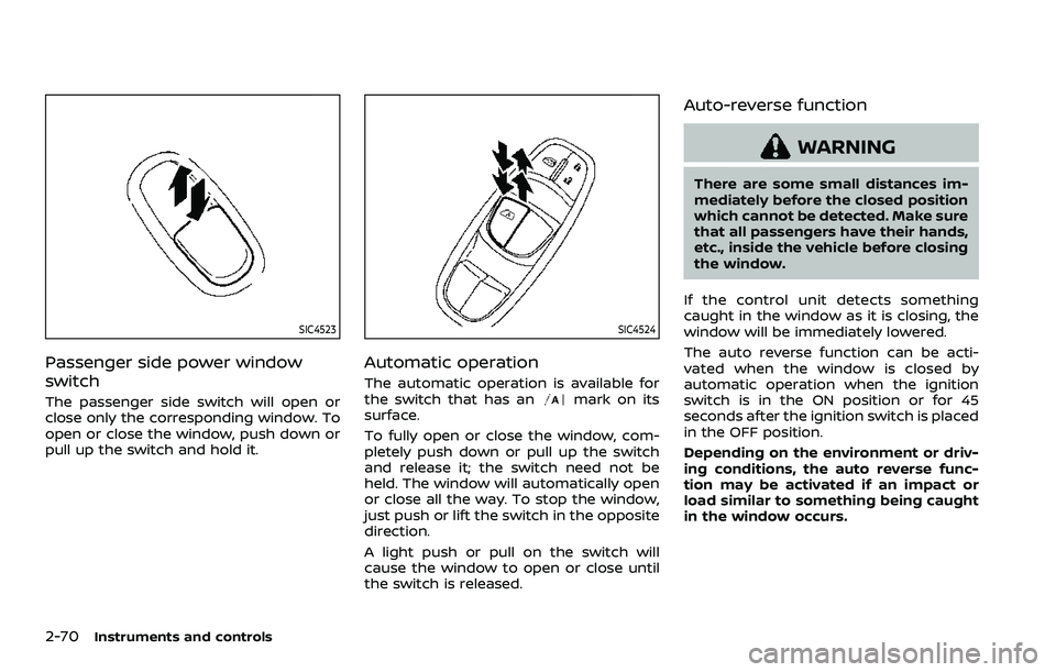
The passenger side switch will open or
close only the corresponding window. To
open or close the window, push down or
pull up the switch and hold it.
SIC4524
Automatic operation
The automatic operation is available for
the switch that has anmark on its
surface.
To fully open or close the window, com-
pletely push down or pull up the switch
and release it; the switch need not be
held. The window will automatically open
or close all the way. To stop the window,
just push or lift the switch in the opposite
direction.
A light push or pull on the switch will
cause the window to open or close until
the switch is released.
Auto-reverse function
WARNING
There are some small distances im-
mediately before the closed position
which cannot be detected. Make sure
that all passengers have their hands,
etc., inside the vehicle before closing
the window.
If the control unit detects something
caught in the window as it is closing, the
window will be immediately lowered.
The auto reverse function can be acti-
vated when the window is closed by
automatic operation when the ignition
switch is in the ON position or for 45
seconds after the ignition switch is placed
in the OFF position.
Depending on the environment or driv-
ing conditions, the auto reverse func-
tion may be activated if an impact or
load similar to something being caught
in the window occurs.
Page 159 of 500
CLEARING THE PROGRAMMED IN-
FORMATION
The following procedure clears the pro-
grammed information from both buttons.
Individual buttons cannot be cleared.
However, individual buttons can be re-
programmed, see “Reprogramming a sin-
gle HomeLink® button” (P.2-79).
To clear all programming
1. Press and hold the two outerHomeLink® buttons until the indicator
light begins to flash in approximately
10 seconds. Do not hold for longer
than 20 seconds.
2. Release both buttons.
HomeLink® is now in the programming
mode and can be programmed at any
time beginning with “Programming
HomeLink®” - Step 1.
REPROGRAMMING A SINGLE
HomeLink® BUTTON
To reprogram a HomeLink® Universal
Transceiver button, complete the follow-
ing.
1. Press and hold the desired HomeLink® button. Do notrelease the button.
2. The indicator light will begin to flash after 20 seconds. Without releasing
the HomeLink® button, proceed with “Programming HomeLink®” - Step 1.
For questions or comments, contact
HomeLink® at: www.homelink.com/
nissan or 1-800-355-3515.
The HomeLink® Universal Transceiver
button has now been reprogrammed.
The new device can be activated by
pushing the HomeLink® button that was
just programmed. This procedure will not
affect any other programmed HomeLink®
buttons.
IF YOUR VEHICLE IS STOLEN
If your vehicle is stolen, you should
change the codes of any non-rolling code
device that has been programmed into
HomeLink®. Consult the Owner’s Manual
of each device or call the manufacturer or
dealer of those devices for additional
information.
When your vehicle is recovered, you will
need to reprogram the HomeLink® Uni-
versal Transceiver with your new trans-
mitter information.
FCC Notice:
For USA:
This device complies with Part 15 of the
FCC Rules. Operation is subject to the
following two conditions: (1) This device
may not cause harmful interference,
and (2) this device must accept any interference received, including inter-
ference that may cause undesired op-
eration.
NOTE:
Changes or modifications not expressly
approved by the party responsible for
compliance could void the user’s
authority to operate the equipment.
For Canada:
This device complies with Industry Ca-
nada licence-exempt RSS standard(s).
Operation is subject to the following
two conditions: (1) this device may not
cause interference, and (2) this device
must accept any interference, including
interference that may cause undesired
operation of the device.
Instruments and controls2-79
Page 167 of 500
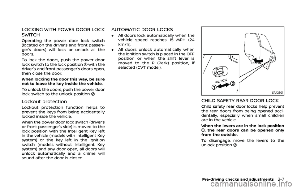
LOCKING WITH POWER DOOR LOCK
SWITCH
Operating the power door lock switch
(located on the driver’s and front passen-
ger’s doors) will lock or unlock all the
doors.
To lock the doors, push the power door
lock switch to the lock position
with the
driver’s and front passenger’s doors open,
then close the door.
When locking the door this way, be sure
not to leave the key inside the vehicle.
To unlock the doors, push the power door
lock switch to the unlock position
.
Lockout protection
Lockout protection function helps to
prevent the keys from being accidentally
locked inside the vehicle.
When the power door lock switch (driver’s
or front passenger’s side) is moved to the
lock position with the Intelligent Key left
in the vehicle (models with Intelligent Key
system) or the key left in the ignition
switch (models without Intelligent Key
system) and any door open, all doors will
unlock automatically and a chime will
sound after the door is closed.
AUTOMATIC DOOR LOCKS
. All doors lock automatically when the
vehicle speed reaches 15 MPH (24
km/h).
. All doors unlock automatically when
the ignition switch is placed in the OFF
position or when the shift lever is
moved to the P (Park) position, if
selected (CVT model).
SPA2801
CHILD SAFETY REAR DOOR LOCK
Child safety rear door locks help prevent
the rear doors from being opened acci-
dentally, especially when small children
are in the vehicle.
When the levers are in the lock position
, the rear doors can be opened only
from the outside.
To disengage, move the levers to the
unlock position
.
Pre-driving checks and adjustments3-7
Page 175 of 500
Welcome light and farewell light
function
When you lock or unlock the doors or the
liftgate, the daytime running lights, park-
ing lights and the tail lights will illuminate
for a period of time. The welcome light
and farewell light function can be dis-
abled. For information about disabling
the welcome light and farewell light
function, see “Vehicle Settings” (P.2-23).
Locking doors
1. Move the shift lever to the P (Park)position (Continuously Variable Trans-
mission (CVT) models), or the shift
lever in the N (Neutral) position (Man-
ual Transmission (MT) models), place
the ignition switch in the OFF position
and make sure you carry the Intelli-
gent Key with you.
2. Close all doors.
3. Push any door handle request switch while carrying the Intelligent Key with
you.
4. All doors and the liftgate will lock.
5. The hazard indicator lights flash twice and the outside buzzer sounds twice.
NOTE:
. Request switches for all doors and
the liftgate can be deactivated when
the I-Key Door Lock setting is turned off in the Vehicle Settings of the
vehicle information display. For ad-
ditional information, see “Vehicle
Settings” (P.2-23).
. Doors lock with the door handle
request switch while the ignition
switch is not in the LOCK position.
. Doors do not lock by pushing the
door handle request switch while
any door is open. However, doors
lock with the mechanical key even if
any door is open.
. Doors do not lock with the door
handle request switch with the In-
telligent Key inside the vehicle and a
beep sounds to warn you. However,
when an Intelligent Key is inside the
vehicle, doors can be locked with
another Intelligent Key.
CAUTION
.After locking the doors using the
request switch, make sure that
the doors have been securely
locked by operating the door
handles or the liftgate opener
switch.
. When locking the doors using the
request switch, make sure to
have the Intelligent Key in your possession before operating the
request switch to prevent the
Intelligent Key from being left in
the vehicle.
. The request switch is operational
only when the Intelligent Key has
been detected by the Intelligent
Key system.
Unlocking doors
1. Push the door handle request switchor the liftgate request switchwhile carrying the Intelligent Key with
you.
2. The hazard indicator flashes once and outside chime sounds once. The cor-
responding door or the liftgate will
unlock.
3. Push the request switch again within 1 minute.
4. The hazard indicator flashes once and outside chime sounds once again. All
the doors and the liftgate will unlock.
All doors will be locked automatically
unless one of the following operations is
performed within 1 minute after pushing
the request switch while the doors are
locked.
. Opening any door.
Pre-driving checks and adjustments3-15