heater NISSAN ROGUE SPORT 2020 Owners Manual
[x] Cancel search | Manufacturer: NISSAN, Model Year: 2020, Model line: ROGUE SPORT, Model: NISSAN ROGUE SPORT 2020Pages: 492, PDF Size: 2.02 MB
Page 7 of 492

Illustrated table of contents0
Safety — Seats, seat belts and supplemental restraint
system1
Instruments and controls
Pre-driving checks and adjustments
Monitor, heater, air conditioner, audio and phone
systems
Starting and driving
In case of emergency
Appearance and care
Do-it-yourself
Maintenance and schedules
Technical and consumer information
2
3
4
5
6
7
8
9
10
Table of
Contents
Index11
Page 15 of 492

WAA0119X
1. Side ventilator (P.4-25)
2. Meters and gauges (P.2-5)/Clock (P.2-42)
3. Center ventilator (P.4-25)
4. Audio system** or navigation system**— RearView Monitor* (P.4-2)
— Intelligent Around View® Monitor*
(P.4-10) — Bluetooth® Hands-Free Phone Sys-
tem**
5. Front passenger supplemental air bag (P.1-42)
6. Fuse box cover (P.8-20)
7. Fuel-filler door release handle (P.3-28)
8. Hood release handle (P.3-25) 9. Steering wheel lock lever (P.3-30)
10. Driver’s front-impact air bag (P.1-42)/Horn
(P.2-59)
11. Driver supplemental knee air bag (P.1-42)
12. Heater/air conditioner control (P.4-26)
13. Auxiliary input jack** and USB connection port**
14. Power outlet (P.2-65)
15. Defroster switch (P.2-52)
16. Passenger supplemental knee air bag (P.1-42)
17. Glove box (P.2-68)
*: if so equipped
**: See the separate NissanConnect® Own- er’s Manual (if so equipped).
Illustrated table of contents0-7
INSTRUMENT PANEL
Page 86 of 492

2-4Instruments and controls
WAA0119X
1. Side ventilator
2. Meters and gauges/Clock
3. Center ventilator
4. Audio system** or navigation system**— RearView Monitor*
— Intelligent Around View® Monitor*
— Bluetooth® Hands-Free Phone Sys- tem**
5. Front passenger supplemental air bag
6. Fuse box cover
7. Fuel-filler door release handle
8. Hood release handle
9. Steering wheel lock lever
10. Driver’s front-impact air bag /Horn 11. Driver supplemental knee air bag
12. Heater/air conditioner control
13. Auxiliary input jack** and USB connection
port**
14. Power outlet
15. Defroster switch
16. Passenger supplemental knee air bag
17. Glove box
*: if so equipped
**: See the separate NissanConnect® Own- er’s Manual (if so equipped).
INSTRUMENT PANEL
Page 142 of 492

2-60Instruments and controls
WARNING
Do not use or allow occupants to use
the seat heater if you or the occu-
pants cannot monitor elevated seat
temperatures or have an inability to
feel pain in body parts that contact
the seat. Use of the seat heater by
such people could result in serious
injury.
CAUTION
.The battery could run down if the
seat heater is operated while the
engine is not running.
. Do not use the seat heater for
extended periods or when no one
is using the seat.
. Do not put anything on the seat
which insulates heat, such as a
blanket, cushion, seat cover, etc.
Otherwise, the seat may become
overheated.
. Do not place anything hard or
heavy on the seat or pierce it with
a pin or similar object. This may
result in damage to the heater. .
Any liquid spilled on the heated
seat should be removed immedi-
ately with a dry cloth.
. When cleaning the seat, never use
gasoline, thinner, or any similar
materials.
. If any malfunctions are found or
the heated seat does not operate,
turn the switch off and have the
system checked. It is recom-
mended you visit a NISSAN dealer
for this service.
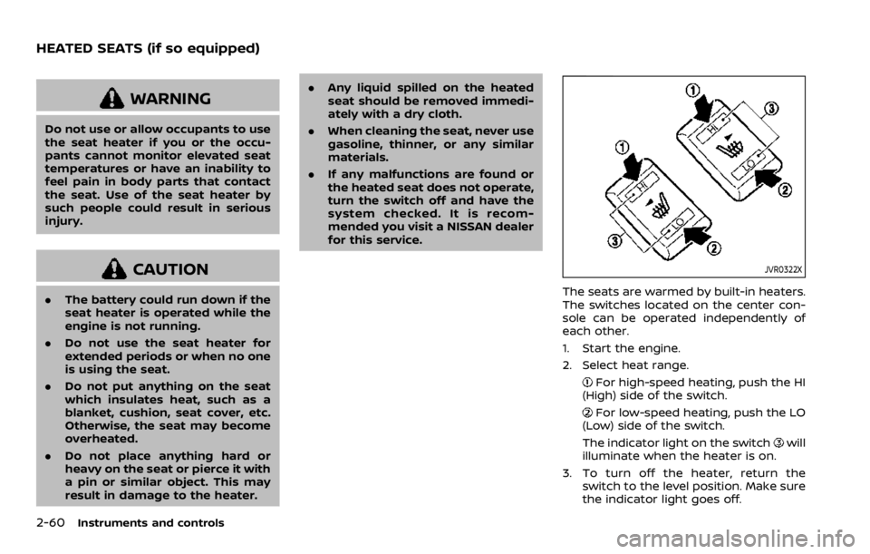
JVR0322X
The seats are warmed by built-in heaters.
The switches located on the center con-
sole can be operated independently of
each other.
1. Start the engine.
2. Select heat range.
For high-speed heating, push the HI
(High) side of the switch.
For low-speed heating, push the LO
(Low) side of the switch.
The indicator light on the switch
will
illuminate when the heater is on.
3. To turn off the heater, return the switch to the level position. Make sure
the indicator light goes off.
HEATED SEATS (if so equipped)
Page 143 of 492

The heater is controlled by a thermo-
stat, automatically turning the heater
on and off. The indicator light will
remain on as long as the switch is on.
When the vehicle’s interior is warmed,
or before you leave the vehicle, be
sure to turn off the switch.
JVI1593X
The dynamic driver assistance switch is
used to temporarily turn on and off the
Intelligent Lane Intervention (I-LI) system.
The I-LI system must be turned on with
the dynamic driver assistance switch
every time the ignition is placed in the
ON position.
When the dynamic driver assistance
switch is turned off, the indicator
on
the switch is off. The indicator will also be
off if the I-LI system is deactivated using
the vehicle information display.
The I-LI system warns the driver with an
indicator and a chime, and helps assist
the driver to return the vehicle to the
center of the traveling lane by applying the brakes to the left or right wheels
individually (for a short period of time). For
additional information, see “Intelligent
Lane Intervention (I-LI)” (P.5-40).
Instruments and controls2-61
DYNAMIC DRIVER ASSISTANCE SWITCH
(models without ProPILOT assist)
Page 203 of 492

4 Monitor, heater, air conditioner, audioand phone systems
NissanConnect® Owner’s Manual .................................... 4-2
RearView Monitor (if so equipped) ................................. 4-2
RearView Monitor system operation ..................... 4-3
How to read the displayed lines ................................ 4-3
Difference between predictive and
actual distances ...................................................................... 4-4
How to park with predictive course lines .......... 4-5
Adjusting the screen ........................................................... 4-7
How to turn ON and OFF predictive course
lines ........................................................................\
......................... 4-7
RearView Monitor system limitations .................... 4-7
System maintenance .......................................................... 4-9
Intelligent Around View® Monitor (if so
equipped) ........................................................................\
................. 4-10 Intelligent Around View® Monitor system
operation ........................................................................\
........... 4-11
Difference between predictive and
actual distances ................................................................... 4-14
How to park with predictive course lines ....... 4-16
How to switch the display ........................................... 4-17
Adjusting the screen ........................................................ 4-18 Intelligent Around View® Monitor system
limitations ........................................................................\
....... 4-18
System maintenance .................................................... 4-20
Moving Object Detection (MOD) (if
so equipped) ........................................................................\
......... 4-21 MOD system operation ................................................ 4-21
Turning MOD on and off ............................................ 4-23
MOD system limitations .............................................. 4-23
System maintenance .................................................... 4-24
Ventilators ........................................................................\
.............. 4-25
Center ventilators ............................................................ 4-25
Side ventilators .................................................................. 4-25
Rear ventilators (if so equipped) .......................... 4-25
Heater and air conditioner ................................................ 4-26 Manual air conditioner and heater .................... 4-27
Automatic air conditioner and heater ............ 4-30
Operating tips (for automatic air
conditioner) ........................................................................\
... 4-33
Servicing air conditioner ............................................. 4-33
Antenna ........................................................................\
.................... 4-33
Car phone or CB radio ......................................................... 4-34
Page 204 of 492

4-2Monitor, heater, air conditioner, audio and phone systems
For models with NissanConnect® system,
refer to NissanConnect® Owner’s Manual
that includes the following information.
For models with NissanConnect® System
and Services featuring Apple CarPlay®
and Android Auto
TM, refer to the Nissan-
Connect® Owner’s Manual regarding the
following information.
Available functions may vary depending
on the models and specifications.
. Audio
. Hands-Free Phone
. Apple CarPlay®
. Android Auto
TM
.NissanConnect® Services powered by
SiriusXM®
. Navigation system
. Voice recognition
. Information and settings viewable on
NissanConnect®
WAE0016X
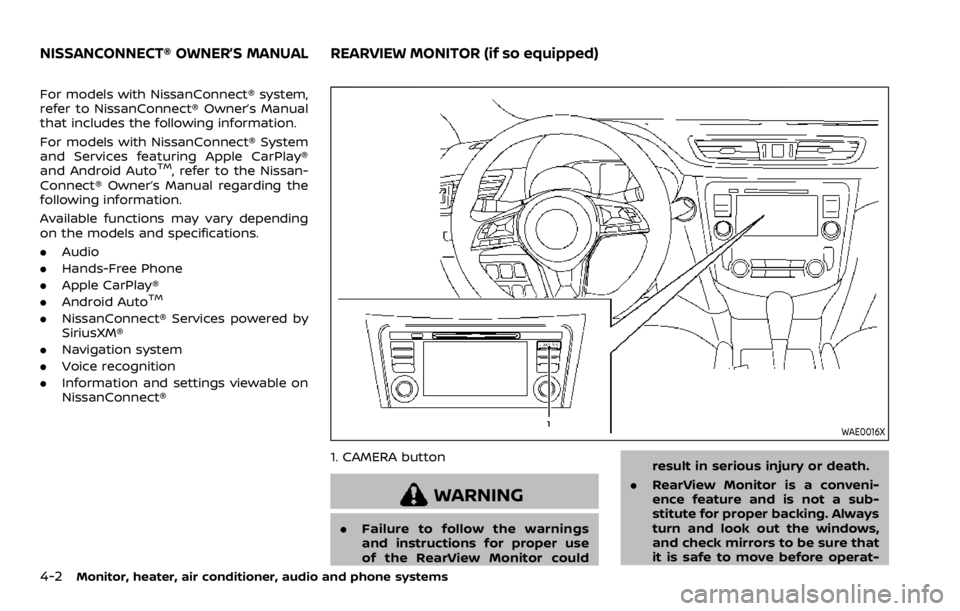
1. CAMERA button
WARNING
.Failure to follow the warnings
and instructions for proper use
of the RearView Monitor could result in serious injury or death.
. RearView Monitor is a conveni-
ence feature and is not a sub-
stitute for proper backing. Always
turn and look out the windows,
and check mirrors to be sure that
it is safe to move before operat-
NISSANCONNECT® OWNER’S MANUALREARVIEW MONITOR (if so equipped)
Page 205 of 492

ing the vehicle. Always back up
slowly.
. The system is designed as an aid
to the driver in showing large
stationary objects directly behind
the vehicle, to help avoid dama-
ging the vehicle.
. The distance guide line and the
vehicle width line should be used
as a reference only when the
vehicle is on a level paved sur-
face. The distance viewed on the
monitor is for reference only and
may be different than the actual
distance between the vehicle and
displayed objects.
CAUTION
Do not scratch the camera lens when
cleaning dirt or snow from the front
of the camera.
The RearView Monitor system automati-
cally shows a rear view of the vehicle
when the shift lever is placed in the R
(Reverse) position.
The radio can still be heard while the
RearView Monitor is active.
JVH1585X
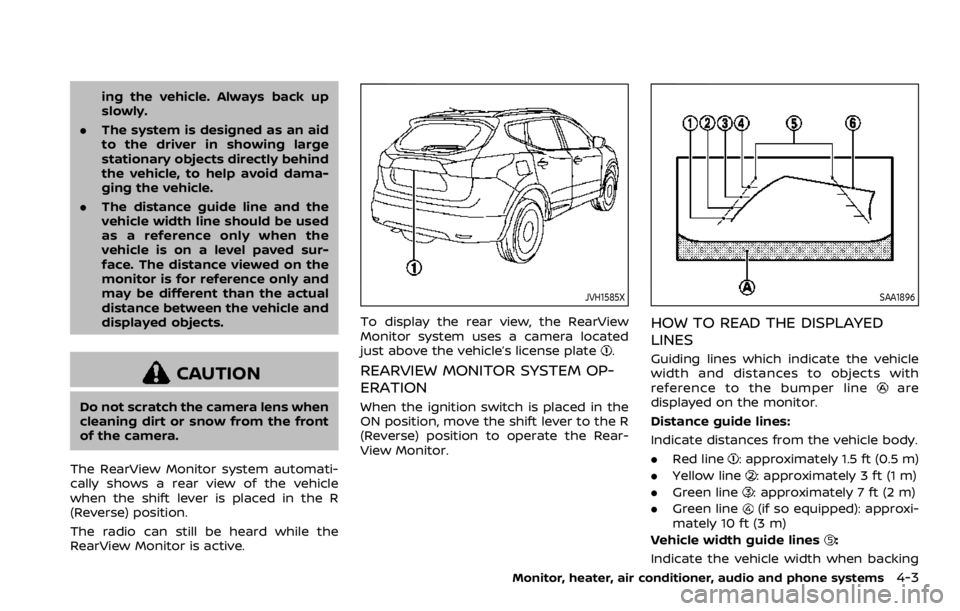
To display the rear view, the RearView
Monitor system uses a camera located
just above the vehicle’s license plate
.
REARVIEW MONITOR SYSTEM OP-
ERATION
When the ignition switch is placed in the
ON position, move the shift lever to the R
(Reverse) position to operate the Rear-
View Monitor.
SAA1896
HOW TO READ THE DISPLAYED
LINES
Guiding lines which indicate the vehicle
width and distances to objects with
reference to the bumper line
are
displayed on the monitor.
Distance guide lines:
Indicate distances from the vehicle body.
. Red line
: approximately 1.5 ft (0.5 m)
. Yellow line
: approximately 3 ft (1 m)
. Green line
: approximately 7 ft (2 m)
. Green line
(if so equipped): approxi-
mately 10 ft (3 m)
Vehicle width guide lines
:
Indicate the vehicle width when backing
Monitor, heater, air conditioner, audio and phone systems4-3
Page 206 of 492

4-4Monitor, heater, air conditioner, audio and phone systems
up.
Predictive course lines
:
Indicate the predictive course when back-
ing up. The predictive course lines will be
displayed on the monitor when the shift
lever is in the R (Reverse) position and if
the steering wheel is turned. The predic-
tive course lines will move depending on
how much the steering wheel is turned
and will not be displayed while the steer-
ing wheel is in the straight ahead position.
The vehicle width guide lines and the
width of the predictive course lines are
wider than the actual width and course.
DIFFERENCE BETWEEN PREDICTIVE
AND ACTUAL DISTANCES
The displayed guidelines and their loca-
tions on the ground are for approximate
reference only. Objects on uphill or down-
hill surfaces or projecting objects will be
actually located at distances different
from those displayed in the monitor
relative to the guidelines (refer to illustra-
tions). When in doubt, turn around and
view the objects as you are backing up, or
park and exit the vehicle to view the
positioning of objects behind the vehicle.
JVH1159X
Backing up on a steep uphill
When backing up the vehicle up a hill, the
distance guide lines and the vehicle width
guide lines are shown closer than the
actual distance. Note that any object on
the hill is farther than it appears on the
monitor.
JVH1160X
Backing up on a steep downhill
When backing up the vehicle down a hill,
the distance guide lines and the vehicle
width guide lines are shown farther than
the actual distance. Note that any object
on the hill is closer than it appears on the
monitor.
Page 207 of 492

SAA1923
Backing up near a projecting object
The predictive course linesdo not
touch the object in the display. However,
the vehicle may hit the object if it projects
over the actual backing up course.
SAA1980
Backing up behind a projecting
object
The positionis shown farther than the
positionin the display. However, the
positionis actually at the same dis-
tance as the position. The vehicle may
hit the object when backing up to the position
if the object projects over the
actual backing up course.
HOW TO PARK WITH PREDICTIVE
COURSE LINES
WARNING
. If the tires are replaced with
different sized tires, the predic-
tive course lines may be dis-
played incorrectly.
. On a snow-covered or slippery
road, there may be a difference
between the predictive course
line and the actual course line.
. If the battery is disconnected or
becomes discharged, the predic-
tive course lines may be dis-
played incorrectly. If this occurs,
please perform the following pro-
cedures:
— Turn the steering wheel from
lock to lock while the engine is
running.
— Drive the vehicle on a straight road for more than 5 minutes.
. When the steering wheel is
turned with the ignition switch in
the ON position, the predictive
course lines may be displayed
Monitor, heater, air conditioner, audio and phone systems4-5