tires NISSAN SENTRA 1997 B14 / 4.G Owners Manual
[x] Cancel search | Manufacturer: NISSAN, Model Year: 1997, Model line: SENTRA, Model: NISSAN SENTRA 1997 B14 / 4.GPages: 194, PDF Size: 1.62 MB
Page 89 of 194
1) Move the shift lever into the P (Park)
position.
2) Turn the ignition key slightly in the ON
direction.
3) Turn the key toward the LOCK position.
4) Remove the key.
If the key is removed from the ignition
switch, the shift lever cannot be moved from
P (Park).The shift lever can be moved if
the ignition switch is in the ACC posi-
tion. The shift lever can also be moved if
the ignition switch is in the ON position
and the foot brake pedal is depressed.
There is an OFF position in between LOCK
and ACC, although it does not show on the
key cylinder. When the ignition is in OFF the
steering wheel is not locked.
In order for the steering wheel to be locked,
it must be turned about 1/8 of a turn coun-
terclockwise from the straight up position,
and the key must be removed from the
ignition.
To lock the steering wheel, remove the
key. To unlock the steering wheel, insert
the key and turn it gently while rotating
the steering wheel slightly right and left.WARNING
Never remove the key while driving. If
the key is removed, the steering wheel
will lock. This may cause the driver to
lose control of the vehicle and could
result in serious vehicle damage or
personal injury.
Key positions
LOCK: Normal parking position (0)
OFF: (Manual transmission model) (1)
The engine can be turned off without locking
the steering wheel.
ACC: (Accessories) (2)
This position activates electrical accesso-
ries such as the radio when the engine is
not running.
ON: Normal operating position (3)
This position turns on the ignition system
and the electrical accessories.
START: (4)
This position activates the starter motor,
which starts the engine.cMake sure the area around the vehicle is
clear.
cMaintenance items listed here should be
checked periodically, e.g., each time you
check engine oil.
cCheck that all windows and lights are
clean.
cVisually inspect tires for their appearance
and condition. Also check tires for proper
inflation.
cLock all doors.
cPosition seat and adjust head restraints.
cAdjust inside and outside mirrors.
cFasten seat belts and ask all passengers
to do likewise.
cCheck the operation of warning lights
when key is turned to the ON (3) position.
BEFORE STARTING THE
ENGINE
4-5
ZX
Page 99 of 194
cKeep your engine tuned up.
cFollow the recommended periodic main-
tenance schedule.
cKeep the tires inflated to the correct
pressure. Low pressure increases tire
wear and wastes fuel.
cKeep the front wheels in correct align-
ment. Improper alignment increases tire
wear and lowers fuel economy.
cAir conditioner operation lowers fuel
economy. Use the air conditioner only
when necessary.
cWhen cruising at highway speeds, it is
more economical to use the air condi-
tioner and leave the windows closed to
reduce drag.
WARNING
Do not park the vehicle over flammable
materials such as dry grass, waste pa-
per or rags. They may ignite and cause
a fire.
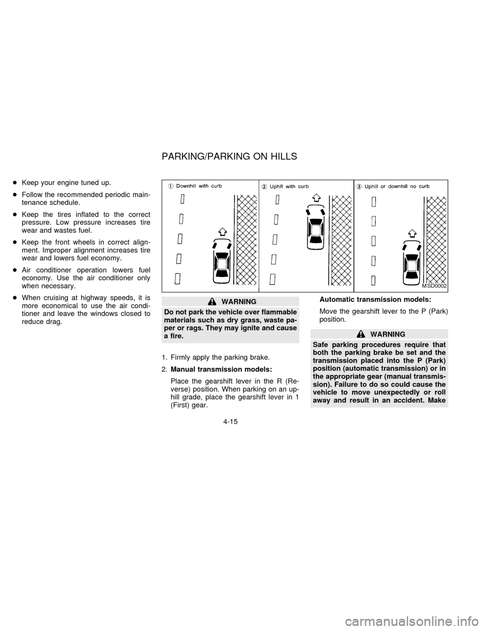
1. Firmly apply the parking brake.
2.Manual transmission models:
Place the gearshift lever in the R (Re-
verse) position. When parking on an up-
hill grade, place the gearshift lever in 1
(First) gear.Automatic transmission models:
Move the gearshift lever to the P (Park)
position.
WARNING
Safe parking procedures require that
both the parking brake be set and the
transmission placed into the P (Park)
position (automatic transmission) or in
the appropriate gear (manual transmis-
sion). Failure to do so could cause the
vehicle to move unexpectedly or roll
away and result in an accident. Make
MSD0002
PARKING/PARKING ON HILLS
4-15
ZX
Page 102 of 194
and releases hydraulic pressure (like pump-
ing the brakes very quickly). While the ac-
tuator is working, you may feel a pulsation in
the brake pedal and hear a noise or vibra-
tion from the actuator under the hood. This
is normal and indicates that the anti-lock
system is working properly. However, the
pulsation may indicate that road conditions
are hazardous and extra care is required
while driving.
Self-test feature
The anti-lock brake system is sophisticated,
with electronic sensors, electric pumps, and
hydraulic solenoids controlled by a com-
puter. The computer has a built-in diagnos-
tic feature that tests the system each time
you start the engine and move the vehicle at
a low speed in forward or reverse. When the
self-test occurs, you may hear a ``clunk''
noise and/or feel a pulsation in the brake
pedal. This is normal and is not an indica-
tion of any malfunction. If the computer
senses any malfunction, it switches the anti-
lock brake system OFF and turns on the
ABS brake warning light in the dashboard.
The brake system then operates normally,
but without anti-lock assistance.
If the light comes on during the self check orwhile driving, take your vehicle to your NIS-
SAN dealer for repair at your earliest con-
venience.
WARNING
cThe anti-lock brake system is a so-
phisticated device, but it cannot pre-
vent accidents resulting from care-
less or dangerous driving tech-
niques. It can help maintain vehicle
control during braking on slippery
surfaces, but remember that the
stopping distance on slippery sur-
faces will be longer than on normal
surfaces, even with the anti-lock
system. Stopping distances may
also be longer on rough, gravel or
snow covered roads, or if you are
using tire chains. Always maintain a
safe distance from the vehicle in
front of you. Ultimately, the respon-
sibility for safety of self and others
rests in the hands of the driver.
cTire type and condition may also
affect braking effectiveness.
cWhen replacing tires, install the
specified size of tires on all 4 wheels.c
When installing a spare tire, make
sure it is the proper size and type as
specified on the tire placard. For tire
placard location information, refer to
``Tire placard'' in the Owner's Manual
index.
cRefer to ``Wheels and tires'' in the
``Do-it-yourself operations'' section
of this manual.
4-18
ZX
Page 103 of 194

Freeing a frozen door lock
To prevent a door lock from freezing, apply
de-icer or glycerin to it through the key hole.
If the lock becomes frozen, heat the key
before inserting it into the key hole.
Anti-freeze
In the winter when it is anticipated that the
temperature will drop below 32ÉF (0ÉC),
check the anti-freeze (ethylene glycol base)
to assure proper winter protection. For de-
tails, see ``Engine cooling system'' in the
``Do-it-yourself operations'' section.
Battery
If the battery is not fully charged during
extremely cold weather conditions, the bat-
tery fluid may freeze and damage the bat-
tery. To maintain maximum efficiency, the
battery should be checked regularly. For
details, see ``Battery'' in the ``Do-it-yourself
operations'' section.
Draining of coolant water
If the vehicle is to be left outside without
anti-freeze, drain the cooling system by
opening the drain valves located under the
radiator and on the engine block. Refillbefore operating the vehicle. See ``Chang-
ing Engine Coolant'' in the ``Do-it-yourself
operations'' section.
Tire equipment
1. SUMMER tires are of a tread design to
provide superior performance on dry
pavement. However, the performance of
these tires will be substantially reduced
in snowy and icy conditions. If you oper-
ate your vehicle on snowy or icy roads,
NISSAN recommends the use of MUD &
SNOW or ALL SEASON TIRES on all
four wheels. Please consult your NIS-
SAN dealer for the tire type, size, speed
rating and availability information.
2. For additional traction on icy roads, stud-
ded tires may be used. However, some
provinces and states prohibit their use.
Check local, state and provincial laws
before installing studded tires.
Skid and traction capabilities of studded
snow tires on wet or dry surfaces may be
poorer than that of non-studded snow
tires.
3. Tire chains may be used if desired. Make
sure they are of proper size for the tires
on your vehicle and are installed accord-ing to the chain manufacturer's sugges-
tions.
Use of tire chains may be prohibited
according to location. Check the local
laws before installing tire chains. When
installing tire chains, make sure they are
of proper size for the tires on your vehicle
and are installed according to the chain
manufacturer's suggestions.Use only
SAE Class ªSº chains.Other types may
damage your vehicle. Use chain tension-
ers when recommended by the tire chain
manufacturer to ensure a tight fit. Loose
end links of the tire chain must be se-
cured or removed to prevent the possi-
bility of whipping action damage to the
fenders or underbody. If possible, avoid
fully loading your vehicle when using tire
chains. In addition, drive at a reduced
speed. Otherwise, your vehicle may be
damaged and/or vehicle handling and
performance may be adversely affected.
Never install tire chains on T-type spare
tires. Do not use tire chains on dry roads.
COLD WEATHER DRIVING
4-19
ZX
Page 106 of 194
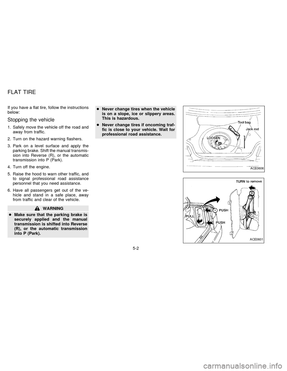
If you have a flat tire, follow the instructions
below:
Stopping the vehicle
1. Safely move the vehicle off the road and
away from traffic.
2. Turn on the hazard warning flashers.
3. Park on a level surface and apply the
parking brake. Shift the manual transmis-
sion into Reverse (R), or the automatic
transmission into P (Park).
4. Turn off the engine.
5. Raise the hood to warn other traffic, and
to signal professional road assistance
personnel that you need assistance.
6. Have all passengers get out of the ve-
hicle and stand in a safe place, away
from traffic and clear of the vehicle.
WARNING
cMake sure that the parking brake is
securely applied and the manual
transmission is shifted into Reverse
(R), or the automatic transmission
into P (Park).cNever change tires when the vehicle
is on a slope, ice or slippery areas.
This is hazardous.
cNever change tires if oncoming traf-
fic is close to your vehicle. Wait for
professional road assistance.
ACE0606
ACE0601
FLAT TIRE
5-2
ZX
Page 110 of 194
cNever jack up the vehicle more than
necessary.
cNever use blocks on or under the
jack.
cDo not start or run engine while
vehicle is on the jack as it may cause
the vehicle to move.
cDo not allow passengers to stay in
the vehicle while it is on the jack.
cNever run the engine with a wheel off
the ground. It may cause the vehicle
to move. This is especially true for
models equipped with limited slip
differential carrier.
Installing wheel
The T-type spare tire is designed for
emergency use. See specific instruc-
tions under the heading ``Wheels and
tires'' in the ``Do-it- yourself operations''
section.
1. Clean any mud or dirt from the surface
between the wheel and hub.
2. Carefully put the spare tire on and tighten
the wheel nuts finger tight.
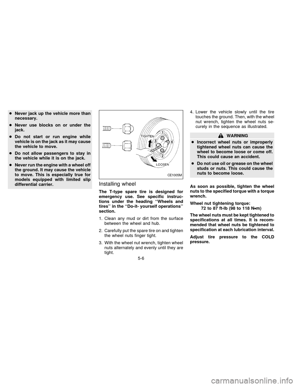
3. With the wheel nut wrench, tighten wheel
nuts alternately and evenly until they are
tight.4. Lower the vehicle slowly until the tire
touches the ground. Then, with the wheel
nut wrench, tighten the wheel nuts se-
curely in the sequence as illustrated.
WARNING
cIncorrect wheel nuts or improperly
tightened wheel nuts can cause the
wheel to become loose or come off.
This could cause an accident.
cDo not use oil or grease on the wheel
studs or nuts. This could cause the
nuts to become loose.
As soon as possible, tighten the wheel
nuts to the specified torque with a torque
wrench.
Wheel nut tightening torque:
72 to 87 ft-lb (98 to 118 N²m)
The wheel nuts must be kept tightened to
specifications at all times. It is recom-
mended that wheel nuts be tightened to
specification at each lubrication interval.
Adjust tire pressure to the COLD
pressure.
CE1005M
5-6
ZX
Page 111 of 194
COLD pressure:
After vehicle has been parked for three
hours or more or driven less than 1 mile
(1.6 km).
COLD tire pressures are shown on thetire placard affixed to the driver side
center pillar.
cRetighten the wheel nuts when the
vehicle has been run for 600 miles
(1,000 km).
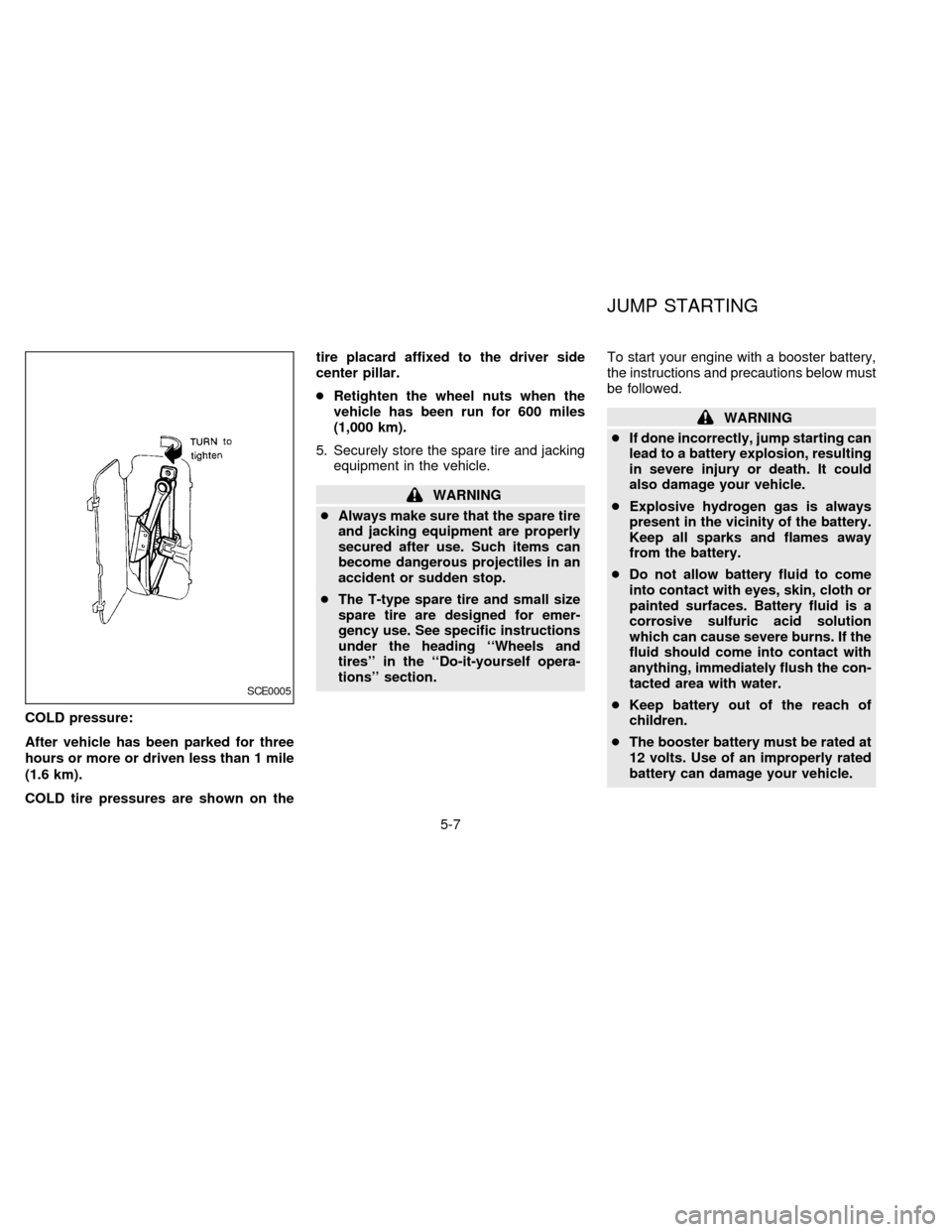
5. Securely store the spare tire and jacking
equipment in the vehicle.
WARNING
cAlways make sure that the spare tire
and jacking equipment are properly
secured after use. Such items can
become dangerous projectiles in an
accident or sudden stop.
cThe T-type spare tire and small size
spare tire are designed for emer-
gency use. See specific instructions
under the heading ``Wheels and
tires'' in the ``Do-it-yourself opera-
tions'' section.To start your engine with a booster battery,
the instructions and precautions below must
be followed.
WARNING
cIf done incorrectly, jump starting can
lead to a battery explosion, resulting
in severe injury or death. It could
also damage your vehicle.
cExplosive hydrogen gas is always
present in the vicinity of the battery.
Keep all sparks and flames away
from the battery.
cDo not allow battery fluid to come
into contact with eyes, skin, cloth or
painted surfaces. Battery fluid is a
corrosive sulfuric acid solution
which can cause severe burns. If the
fluid should come into contact with
anything, immediately flush the con-
tacted area with water.
cKeep battery out of the reach of
children.
cThe booster battery must be rated at
12 volts. Use of an improperly rated
battery can damage your vehicle.
SCE0005
JUMP STARTING
5-7
ZX
Page 116 of 194
CAUTION
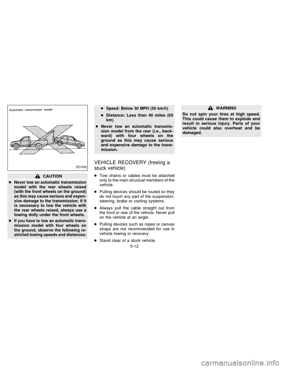
c
Never tow an automatic transmission
model with the rear wheels raised
(with the front wheels on the ground)
as this may cause serious and expen-
sive damage to the transmission. If it
is necessary to tow the vehicle with
the rear wheels raised, always use a
towing dolly under the front wheels.
cIf you have to tow an automatic trans-
mission model with four wheels on
the ground, observe the following re-
stricted towing speeds and distances:cSpeed: Below 30 MPH (50 km/h)
cDistance: Less than 40 miles (65
km)
cNever tow an automatic transmis-
sion model from the rear (i.e., back-
ward) with four wheels on the
ground as this may cause serious
and expensive damage to the trans-
mission.
VEHICLE RECOVERY (freeing a
stuck vehicle)
cTow chains or cables must be attached
only to the main structual members of the
vehicle.
cPulling devices should be routed so they
do not touch any part of the suspension,
steering, brake or cooling systems.
cAlways pull the cable straight out from
the front or rear of the vehicle. Never pull
on the vehicle at an angle.
cPulling devices such as ropes or canvas
straps are not recommended for use in
vehicle towing or recovery.
cStand clear of a stuck vehicle.
WARNING
Do not spin your tires at high speed.
This could cause them to explode and
result in serious injury. Parts of your
vehicle could also overheat and be
damaged.
CE1052
5-12
ZX
Page 123 of 194

7Do-it-yourself operations
Maintenance precautions .......................................7-2
Engine compartment check locations -
GA engine .............................................................7-3
Engine compartment check locations -
SR engine ..............................................................7-4
Engine cooling system ...........................................7-5
Checking engine coolant level ...............................7-5
Changing engine coolant .......................................7-6
Engine oil ...............................................................7-8
Checking engine oil level .......................................7-8
Changing engine oil ...............................................7-9
Changing engine oil filter .....................................7-10
Automatic transmission fluid (ATF) ......................7-11
Temperature conditions for checking ATF ...........7-12
Power steering fluid..............................................7-13
Brake fluid ............................................................7-14
Window washer fluid ............................................7-14
Battery ..................................................................7-15Jump starting ........................................................7-16
Drive belts ............................................................7-17
Spark plug replacement .......................................7-18
Air cleaner housing filter ......................................7-19
Wiper blades ........................................................7-20
Parking brake check.............................................7-21
Brake pedal ..........................................................7-21
Brake booster .......................................................7-22
Clutch pedal .........................................................7-23
Fuses ....................................................................7-23
Light bulbs ............................................................7-25
Headlights ............................................................7-25
Headlight aiming adjustment ................................7-26
Bulb replacement .................................................7-26
Front fog light bulb replacement (if so
equipped) .............................................................7-31
Wheels and tires ..................................................7-32
ZX
Page 148 of 194
cAiming is not necessary after replac-
ing the bulb.
cDo not leave the bulb out of the
headlight reflector for a long period
of time as dust, moisture, and smoke
may enter the headlight body and
affect the performance of the head-
light.
Before adjusting the headlights, make sure
all of the tires are properly inflated, the
vehicle is on level ground and there is no
excess weight in the vehicle that would
affect the level of the vehicle.
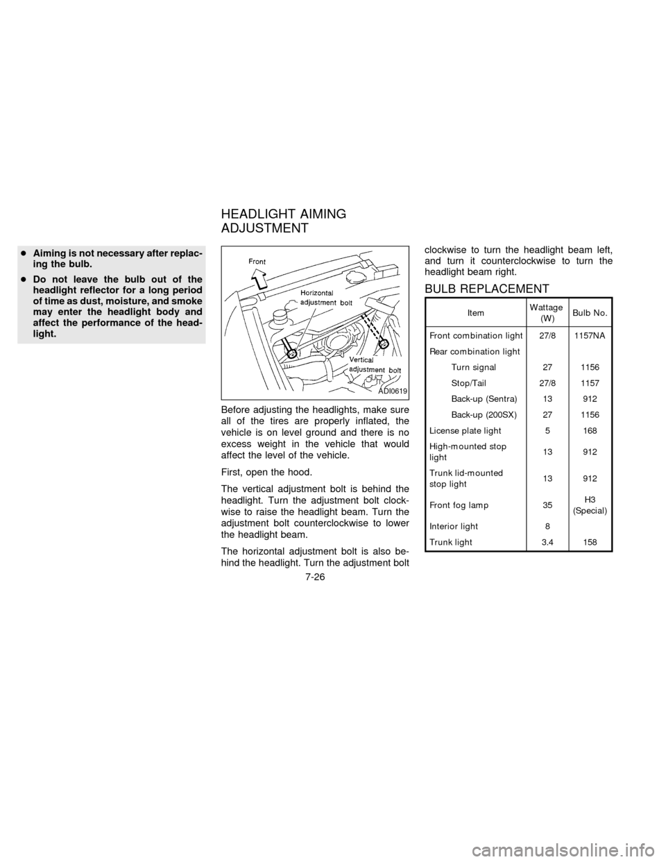
First, open the hood.
The vertical adjustment bolt is behind the
headlight. Turn the adjustment bolt clock-
wise to raise the headlight beam. Turn the
adjustment bolt counterclockwise to lower
the headlight beam.
The horizontal adjustment bolt is also be-
hind the headlight. Turn the adjustment boltclockwise to turn the headlight beam left,
and turn it counterclockwise to turn the
headlight beam right.
BULB REPLACEMENT
ItemWattage
(W)Bulb No.
Front combination light 27/8 1157NA
Rear combination light
Turn signal 27 1156
Stop/Tail 27/8 1157
Back-up (Sentra) 13 912
Back-up (200SX) 27 1156
License plate light 5 168
High-mounted stop
light13 912
Trunk lid-mounted
stop light13 912
Front fog lamp 35H3
(Special)
Interior light 8
Trunk light 3.4 158
ADI0619
HEADLIGHT AIMING
ADJUSTMENT
7-26
ZX