ABS NISSAN SENTRA 2020 Owner´s Manual
[x] Cancel search | Manufacturer: NISSAN, Model Year: 2020, Model line: SENTRA, Model: NISSAN SENTRA 2020Pages: 528, PDF Size: 3.56 MB
Page 21 of 528
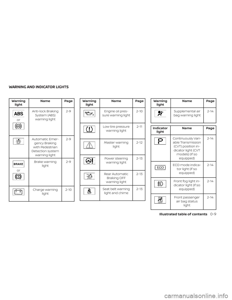
Warninglight Name Page
or
Anti-lock Braking
System (ABS)warning light 2-9
Automatic Emer-
gency Braking
with Pedestrian
Detection system warning light 2-9
or
Brake warning
light 2-9
Charge warning
light 2-10
Warning
light Name Page
Engine oil pres-
sure warning light 2-10
Low tire pressure
warning light 2-11
Master warning
light 2-12
Power steering
warning light 2-13
Rear Automatic
Braking OFF
warning light 2-13
Seat belt warning
light and chime 2-13
Warning
light Name Page
Supplemental air
bag warning light 2-14
Indicator
light Name Page
Continuously Vari-
able Transmission (CVT) position in-
dicator light (CVT models) (if soequipped) 2-14
ECO mode indica-
tor light (if soequipped) 2-14
Front fog light in-
dicator light (if so equipped) 2-14
Front passenger
air bag status light 2-14
WARNING AND INDICATOR LIGHTS
Illustrated table of contents0-9
Page 98 of 528
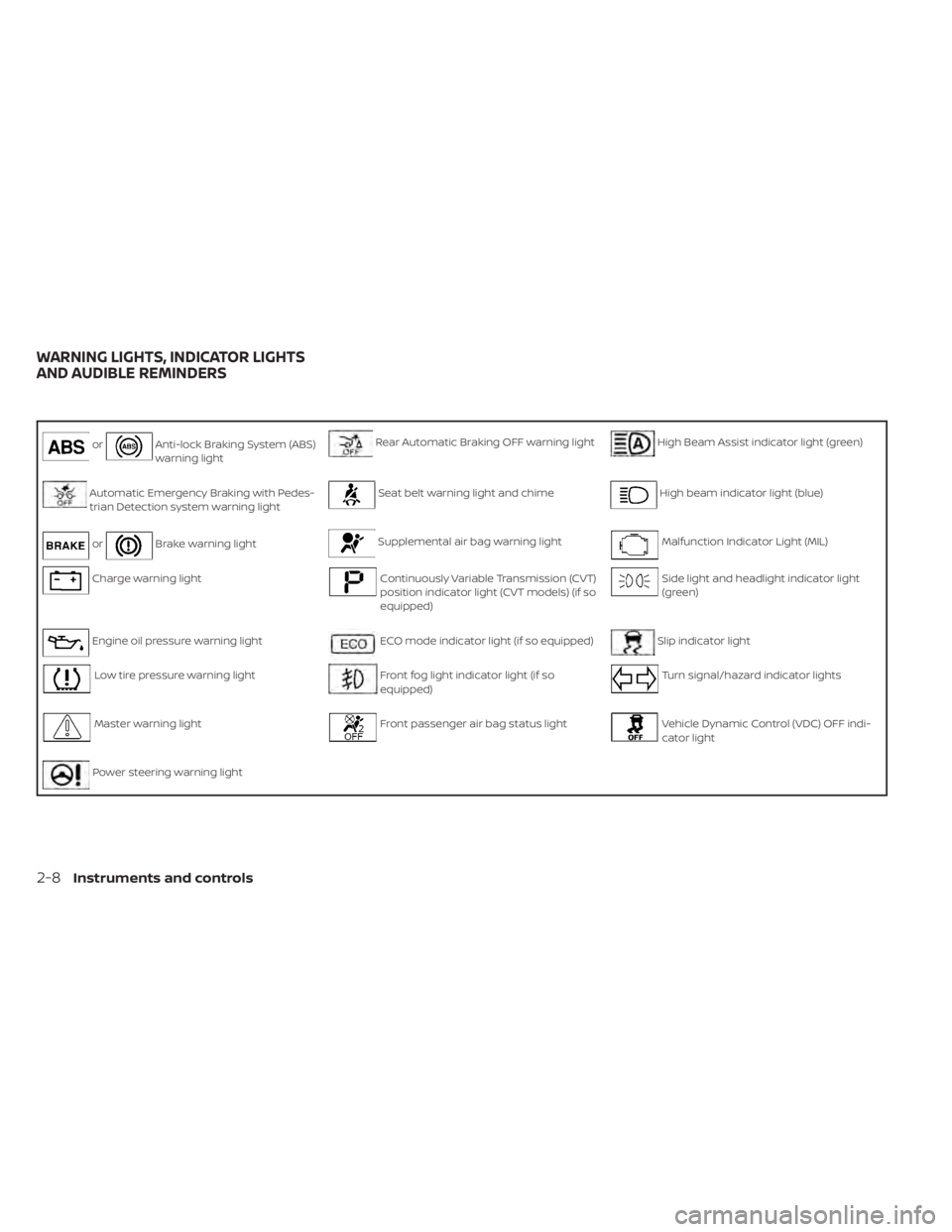
orAnti-lock Braking System (ABS)
warning lightRear Automatic Braking OFF warning lightHigh Beam Assist indicator light (green)
Automatic Emergency Braking with Pedes-
trian Detection system warning lightSeat belt warning light and chimeHigh beam indicator light (blue)
orBrake warning lightSupplemental air bag warning lightMalfunction Indicator Light (MIL)
Charge warning lightContinuously Variable Transmission (CVT)
position indicator light (CVT models) (if so
equipped)Side light and headlight indicator light
(green)
Engine oil pressure warning lightECO mode indicator light (if so equipped)Slip indicator light
Low tire pressure warning lightFront fog light indicator light (if so
equipped)Turn signal/hazard indicator lights
Master warning lightFront passenger air bag status lightVehicle Dynamic Control (VDC) OFF indi-
cator light
Power steering warning light
WARNING LIGHTS, INDICATOR LIGHTS
AND AUDIBLE REMINDERS
2-8Instruments and controls
Page 99 of 528
CHECKING LIGHTS
With all doors closed, apply the parking
brake, fasten the seat belts and place the
ignition switch in the ON position without
starting the engine. The following lights (if
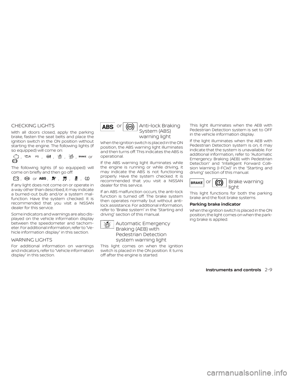
so equipped) will come on:
,,,,,or
The following lights (if so equipped) will
come on briefly and then go off:
,or,,,,
If any light does not come on or operate in
a way other than described, it may indicate
a burned-out bulb and/or a system mal-
function. Have the system checked. It is
recommended that you visit a NISSAN
dealer for this service.
Some indicators and warnings are also dis-
played on the vehicle information display
between the speedometer and tachom-
eter. For additional information, refer to “Ve-
hicle information display” in this section.
WARNING LIGHTS
For additional information on warnings
and indicators, refer to “Vehicle information
display” in this section.
orAnti-lock Braking
System (ABS)
warning light
When the ignition switch is placed in the ON
position, the ABS warning light illuminates
and then turns off. This indicates the ABS is
operational.
If the ABS warning light illuminates while
the engine is running or while driving, it
may indicate the ABS is not functioning
properly. Have the system checked. It is
recommended that you visit a NISSAN
dealer for this service.
If an ABS malfunction occurs, the anti-lock
function is turned off. The brake system
then operates normally but without anti-
lock assistance. For additional information,
refer to “Brake system” in the “Starting and
driving” section of this manual.
Automatic Emergency
Braking (AEB) with
Pedestrian Detection
system warning light
This light comes on when the ignition
switch is placed in the ON position. It turns
off af ter the engine is started.This light illuminates when the AEB with
Pedestrian Detection system is set to OFF
in the vehicle information display.
If the light illuminates when the AEB with
Pedestrian Detection system is on, it may
indicate that the system is unavailable. For
additional information, refer to “Automatic
Emergency Braking (AEB) with Pedestrian
Detection” and “Intelligent Forward Colli-
sion Warning (I-FCW)” in the “Starting and
driving” section of this manual.
orBrake warning
light
This light functions for both the parking
brake and the foot brake systems.
Parking brake indicator
When the ignition switch is placed in the ON
position, the light comes on when the park-
ing brake is applied.
Instruments and controls2-9
Page 278 of 528
• Call HistoryDisplays the Call History screen. For addi-
tional information, refer to “Making a call”
in this section.
• Dial Number Displays the Dial Number screen. For ad-
ditional information, refer to “Making a
call” in this section.
• Text Message Displays the received message screen.
For additional information, refer to “Text
messaging” in this section.
• Connections Displays the Connections screen. For ad-
ditional information, refer to “Bluetooth®
connections screen” in this section.
• Volume Displays the volume adjustment screen.
For additional information, refer to “Vol-
ume & beeps” in this section.MAKING A CALL
To make a call press thebutton on the
control panel. Touch an option from menu
screen:
• Phonebook Select a person and the phone number
you wish to call from the phonebook.
Depending on the device, the phonebook
will be downloaded from the cellular
phone automatically when it is con-
nected. If the automatic download does
not take place, the phone number must
be transferred to the hands-free phone
system from the cellular phone prior to
using this method. For additional infor-
mation, refer to “Phone and text message
settings” in this section.
• Call History Select a phonebook name or phone
number from the recent incoming, out-
going or missed calls tabs. Touch a
phonebook name or phone number
listed to initiate the call.
• Dial Number Enter the phone number manually using
the keypad displayed on the screen.
Touch the “OK” key on the screen to initi-
ate the call.
For additional options to make a call, refer
to “Voice commands” in this section.
Quick Dial
Quick Dial entries can be used to quickly
make a call. The system allows up to 20
entries to be stored. To set up a quick dial
press the
button on the control panel.
Touch the “Quick Dial” key to display a list of
quick dial entries. Touch the “Edit” key to
edit current entries or touch the “Add New”
key to make a new entry. Two methods are
given to create a quick dial entry:
• Touch the “Copy from Call History ” key to save a phone number from the Incoming,
Outgoing or Missed call history lists. Se-
lect the person or phone number from
the menu to be added. A registration
menu will display the Entry #, phone num-
ber, phone number type stored in the cel-
lular phone and Voice Tag. Select the “OK”
key.
• Touch the “Copy from Phonebook” key to save a number from the phonebook. Use
the scroll keys on the side to move up and
down through the menu. Select a person
to be added. A menu will display the Entry
#, phone number, phone number type
stored in the cellular phone and Voice
Tag. Select the “OK” key.
4-76Monitor, climate, audio, phone and voice recognition systems
Page 289 of 528
Increasing fuel economy.......................5-111
Parking/parking on hills .......................5-112
Power steering ................................ 5-113
Brake system ................................. 5-114
Brake precautions .......................... 5-114
Anti-lock Braking System (ABS) .............5-114
Brake Assist ................................ 5-116
Vehicle Dynamic Control (VDC) system ........5-116
Rise-up and build-up ....................... 5-118
Brake force distribution ....................5-118
Chassis Control ............................... 5-119
Intelligent Trace Control (I-TC) ..............5-119
Active Ride Control (ARC) ...................5-119
Hill start assist system ........................ 5-119
Rear Sonar System (RSS) ......................5-120System operation
.......................... 5-121
How to enable/disable the sonar
system ..................................... 5-122
Sonar limitations ........................... 5-124
System temporarily unavailable ............5-124
System maintenance ......................5-125
Cold weather driving .......................... 5-125
Freeing a frozen door lock ..................5-125
Antifreeze .................................. 5-125
Battery..................................... 5-125
Draining of coolant water ..................5-126
Tire equipment ............................. 5-126
Special winter equipment ..................5-126
Driving on snow or ice ......................5-126
Engine block heater (if so equipped) ........5-127
Page 350 of 528
Operating ICC
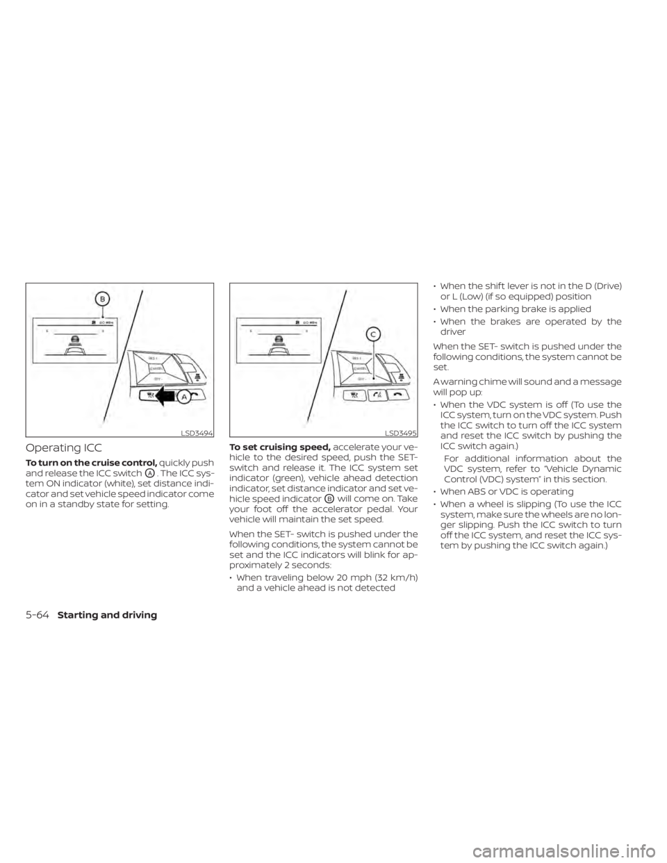
To turn on the cruise control,quickly push
and release the ICC switch
OA. The ICC sys-
tem ON indicator (white), set distance indi-
cator and set vehicle speed indicator come
on in a standby state for setting. To set cruising speed,
accelerate your ve-
hicle to the desired speed, push the SET-
switch and release it. The ICC system set
indicator (green), vehicle ahead detection
indicator, set distance indicator and set ve-
hicle speed indicator
OBwill come on. Take
your foot off the accelerator pedal. Your
vehicle will maintain the set speed.
When the SET- switch is pushed under the
following conditions, the system cannot be
set and the ICC indicators will blink for ap-
proximately 2 seconds:
• When traveling below 20 mph (32 km/h) and a vehicle ahead is not detected • When the shif t lever is not in the D (Drive)
or L (Low) (if so equipped) position
• When the parking brake is applied
• When the brakes are operated by the driver
When the SET- switch is pushed under the
following conditions, the system cannot be
set.
A warning chime will sound and a message
will pop up:
• When the VDC system is off (To use the ICC system, turn on the VDC system. Push
the ICC switch to turn off the ICC system
and reset the ICC switch by pushing the
ICC switch again.)
For additional information about the
VDC system, refer to “Vehicle Dynamic
Control (VDC) system” in this section.
• When ABS or VDC is operating
• When a wheel is slipping (To use the ICC system, make sure the wheels are no lon-
ger slipping. Push the ICC switch to turn
off the ICC system, and reset the ICC sys-
tem by pushing the ICC switch again.)
LSD3494LSD3495
5-64Starting and driving
Page 354 of 528
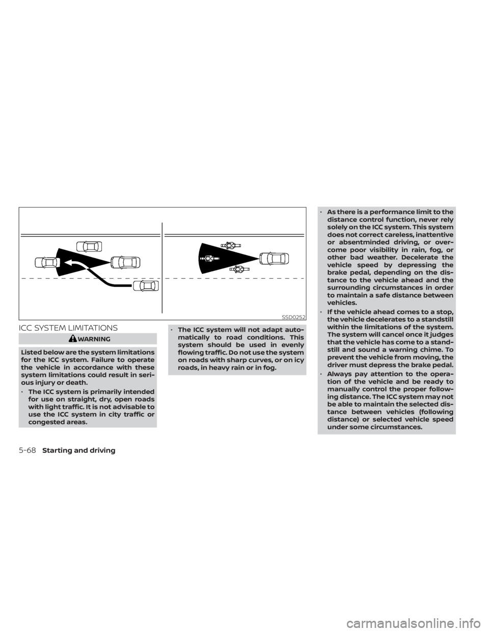
ICC SYSTEM LIMITATIONS
WARNING
Listed below are the system limitations
for the ICC system. Failure to operate
the vehicle in accordance with these
system limitations could result in seri-
ous injury or death.
• The ICC system is primarily intended
for use on straight, dry, open roads
with light traffic. It is not advisable to
use the ICC system in city traffic or
congested areas. •
The ICC system will not adapt auto-
matically to road conditions. This
system should be used in evenly
flowing traffic. Do not use the system
on roads with sharp curves, or on icy
roads, in heavy rain or in fog. •
As there is a performance limit to the
distance control function, never rely
solely on the ICC system. This system
does not correct careless, inattentive
or absentminded driving, or over-
come poor visibility in rain, fog, or
other bad weather. Decelerate the
vehicle speed by depressing the
brake pedal, depending on the dis-
tance to the vehicle ahead and the
surrounding circumstances in order
to maintain a safe distance between
vehicles.
• If the vehicle ahead comes to a stop,
the vehicle decelerates to a standstill
within the limitations of the system.
The system will cancel once it judges
that the vehicle has come to a stand-
still and sound a warning chime. To
prevent the vehicle from moving, the
driver must depress the brake pedal.
• Always pay attention to the opera-
tion of the vehicle and be ready to
manually control the proper follow-
ing distance. The ICC system may not
be able to maintain the selected dis-
tance between vehicles (following
distance) or selected vehicle speed
under some circumstances.
SSD0252
5-68Starting and driving
Page 357 of 528
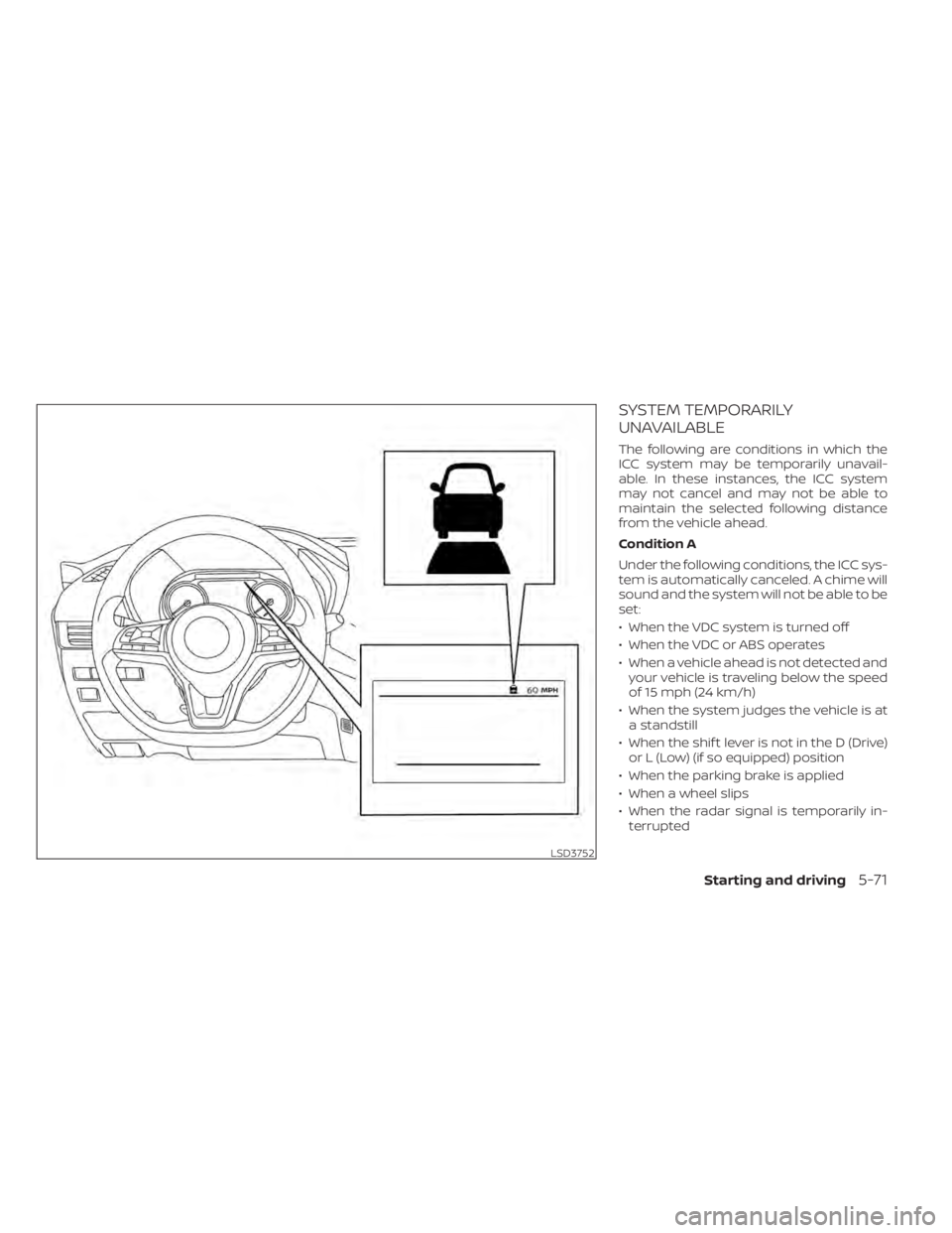
SYSTEM TEMPORARILY
UNAVAILABLE
The following are conditions in which the
ICC system may be temporarily unavail-
able. In these instances, the ICC system
may not cancel and may not be able to
maintain the selected following distance
from the vehicle ahead.
Condition A
Under the following conditions, the ICC sys-
tem is automatically canceled. A chime will
sound and the system will not be able to be
set:
• When the VDC system is turned off
• When the VDC or ABS operates
• When a vehicle ahead is not detected andyour vehicle is traveling below the speed
of 15 mph (24 km/h)
• When the system judges the vehicle is at a standstill
• When the shif t lever is not in the D (Drive) or L (Low) (if so equipped) position
• When the parking brake is applied
• When a wheel slips
• When the radar signal is temporarily in- terrupted
LSD3752
Starting and driving5-71
Page 365 of 528
–Objects that suddenly appear
– Thin objects such as rope, wire,
chain, etc.
• The RAB system may not operate for
the following obstacles:
– Obstacles located high off the
ground
– Obstacles in a position offset from
your vehicle
– Obstacles, such as spongy materi-
als or snow, that have sof t outer
surfaces and can easily absorb a
sound wave
• The RAB system may not operate in
the following conditions:
– There is rain, snow, ice, dirt, etc.,
attached to the sonar sensors.
– A loud sound is heard in the area
around the vehicle.
– The surface of the obstacle is di-
agonal to the rear of the vehicle.
• The RAB system may unintentionally
operate in the following conditions:
– There is overgrown grass in the
area around the vehicle. –
There is a structure (e.g., a wall, toll
gate equipment, a narrow tunnel,
a parking lot gate) near the side of
the vehicle.
– There are bumps, protrusions, or
manhole covers on the road
surface.
– The vehicle drives through a
draped flag or a curtain.
– There is an accumulation of snow
or ice behind the vehicle.
– An ultrasonic wave source, such as
another vehicle’s sonar, is near
the vehicle.
• Once the automatic brake control
operates, it does not operate again if
the vehicle approaches the same
obstacle.
• The automatic brake control can only
operate for a short period of time.
Therefore, the driver must depress
the brake pedal.
• In the following situations, the RAB
system may not operate properly or
may not function sufficiently:
– The vehicle is driven in bad
weather (rain, fog, snow, etc.).
– The vehicle is driven on a steep
hill. –
The vehicle’s posture is changed
(e.g., when driving over a bump).
– The vehicle is driven on a slippery
road.
– The vehicle is turned sharply by
turning the steering wheel fully.
– Snow chains are used.
– Wheels or tires other than NISSAN
recommended are used.
– The brakes are cold at low ambi-
ent temperatures or immediately
af ter driving has started.
– The braking force becomes poor
due to wet brakes af ter driving
through a puddle or washing the
vehicle.
• Turn the RAB system off in the follow-
ing conditions to prevent the occur-
rence of an unexpected accident re-
sulting from sudden system
operation:
– The vehicle is towed.
– The vehicle is carried on a flatbed
truck.
– The vehicle is on the chassis
dynamometer.
– The vehicle drives on an uneven
road surface.
Starting and driving5-79
Page 400 of 528
The brake system has two separate hy-
draulic circuits. If one circuit malfunctions,
you will still have braking at two wheels.
BRAKE PRECAUTIONS
Vacuum assisted brakes
The brake booster aids braking by using
engine vacuum. If the engine stops, you
can stop the vehicle by depressing the
brake pedal. However, greater foot pres-
sure on the brake pedal will be required to
stop the vehicle and stopping distance will
be longer.
Using the brakes
Avoid resting your foot on the brake pedal
while driving. This will overheat the brakes,
wear out the brake pads faster, and reduce
gas mileage.
To help reduce brake wear and to prevent
the brakes from overheating, reduce speed
and downshif t to a lower gear before going
down a slope or long grade. Overheated
brakes may reduce braking performance
and could result in loss of vehicle control.
WARNING
• While driving on a slippery surface,
be careful when braking, accelerat-
ing or downshif ting. Abrupt braking
or accelerating could cause the
wheels to skid and result in an
accident.
• If the engine is not running or is
turned off while driving, the power
assist for the brakes will not work.
Braking will be harder.
Wet brakes
When the vehicle is washed or driven
through water, the brakes may get wet. As
a result, your braking distance will be lon-
ger and the vehicle may pull to one side
during braking.
To dry the brakes, drive the vehicle at a safe
speed while lightly pressing the brake
pedal to heat up the brakes. Do this until
the brakes return to normal. Avoid driving
the vehicle at high speeds until the brakes
function correctly.
Parking brake break-in
Break in the parking brake shoes whenever
the stopping effect of the parking brake is
weakened or whenever the parking brake
shoes and/or drums/rotors are replaced,
in order to assure the best braking perfor-
mance.
This procedure is described in the vehicle
service manual. It is recommended that
you visit a NISSAN dealer for this service.
ANTI-LOCK BRAKING SYSTEM (ABS)
WARNING
• The ABS is a sophisticated device, but
it cannot prevent accidents resulting
from careless or dangerous driving
techniques. It can help maintain ve-
hicle control during braking on slip-
pery surfaces. Remember that stop-
ping distances on slippery surfaces
will be longer than on normal sur-
faces even with ABS. Stopping dis-
tances may also be longer on rough,
gravel or snow covered roads, or if
you are using tire chains. Always
maintain a safe distance from the ve-
hicle in front of you. Ultimately, the
driver is responsible for safety.
BRAKE SYSTEM
5-114Starting and driving