NISSAN SERENA 1993 Service Repair Manual
SERENA 1993
NISSAN
NISSAN
https://www.carmanualsonline.info/img/5/57387/w960_57387-0.png
NISSAN SERENA 1993 Service Repair Manual
Trending: wiring diagram, high beam, coolant, check engine, door lock, oil reset, fuel pump
Page 901 of 1254
REAN
DRUM
BBAXE
ffi@ lnstallation
(Confd)
4. Conn&t parking
bdke €bl6lo lolgle l*t,
0, Ohe.k all part3
ar€ instEll6d prop6ny.
Fby dbndon to
dbdon ot diusbi
€. When lnstalling n4 whel cylind€r or ov€'heling wh*l
oyrind6r, ble6d air. Feter to 'Bl4di.g
pl@do€' ln "AlR
BLEEOING".
BR.Zz
Page 902 of 1254
PARKING
BRAKE CONTROL
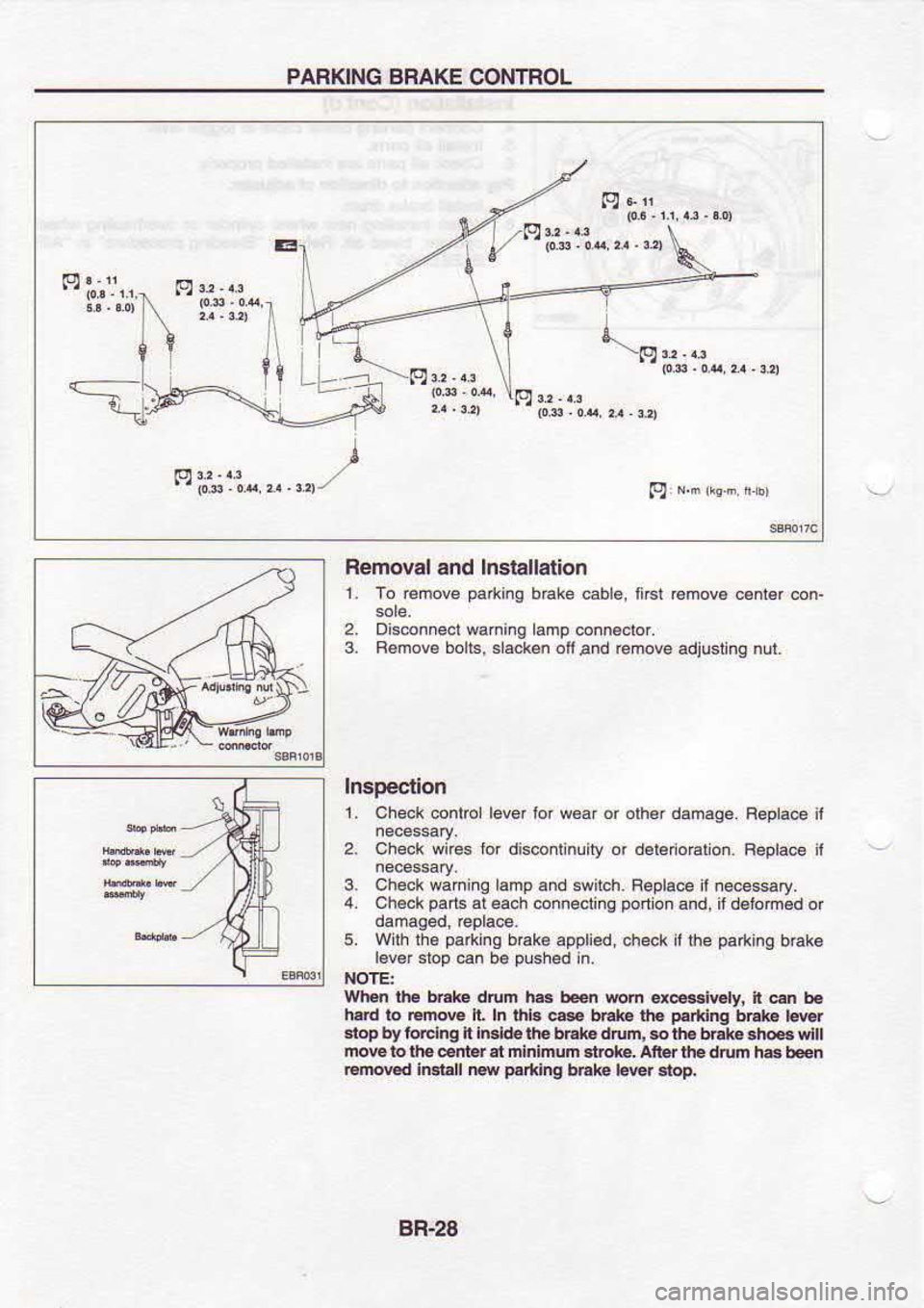
Removal and lnstallation
1. To remove pad{i.g
bake eble, ftst romove cenld con-
Disconnect wariing amp enn€crof.
R6mov€ boll6, slacken
ofi and remove
adjusbng nut.
2.
3.
Inspection
2. 1,
Check.onto lever for woaf or olh€r damage
Check wnes tor disconlinliry or deledo@lon.
3. Checkwahing lamp and
iwitch Feplace I necessary.
4. Ch€ck paris
at each connectino portion
and, it d€lom€d or
5. Wilh lhe pa*ing
brake applied, check if ihe pafting
bdk6
r6v€f sroD
can be Dlshed in.
NOTE:
Wt€n ihE b..k drum h.r
ben mm ex€siGty, it en b6
h.rd to Em@
E h thb c@ bEk€ th.
F*ing bEl€
l€wf
slop by ioElng ft In.ld6lho bhl€ drun, $ th.
bEle.tF! vill
mow to lho 6ni.r et frininun 3tot4
aner th drum ha ben
€mEd in.r.ll |Ew pr*ing
bhke lerer stop,
BB-28
Page 903 of 1254
PARKING
BRAKE CONTROL
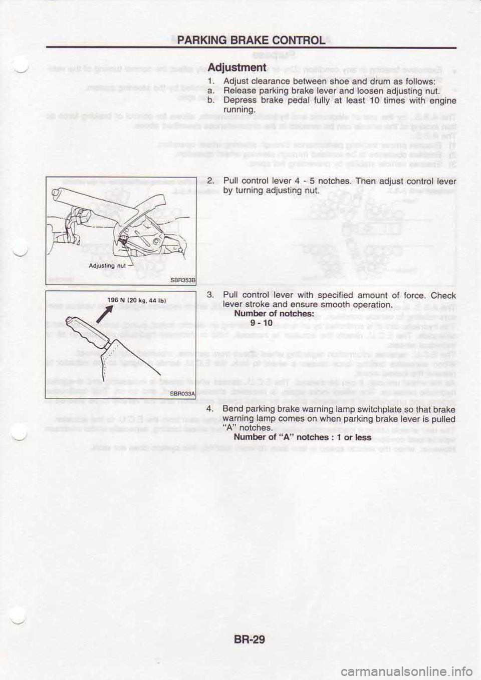
Adiuslmenl 1 . Adiust
cleaEnce between sh@ and drum as lollow.:
a. Felease parkins
bEke lBv€r
and [email protected]
adjustinq nu.t.
b. Deprcss b€k€ p€dal
lully at least 10 time wilh 6ngin6
2. Plll @ntro lever 4 5 notch€s. Then
adjusi @ntor tev€.
by tunifg adjust n9 nut
3. Pull @mrol lEvBr with spe.ilied
ahou|l ot torc€. Check
ever slok6snd 6n5!r6
snoolh ope€lion.
Nufrb.r ol nd!ch6:
4. Bend parking
bEke waning lamp
swiichptats so lhat
b.ake
waninq ramp comes
on when pafting
b€ke l€ver
is puled
Numb.r of
"A" mtch6
: 1 d bs
8R.29
Page 904 of 1254
ANTI.LOCK
BRAKING SYSTEM
PurDose
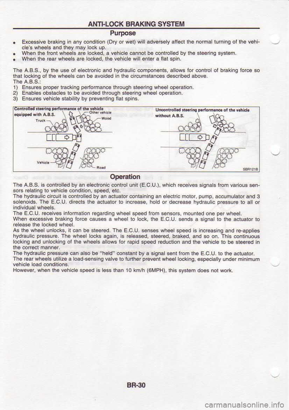
. Ex@ssi@ braking in
any .ondilion (Dry
or w€t) wi I advers€ly atf€cl lh€ nomal llh ng ot lh6 v6hi'
oles wheels and they may
Lo.k
uP.
. whenlhe to.i wheels are lo.ked, a vehicle
ca.nol be controled by
lhe
sleenno syst€m.
. When
dre Garwhees are locked,lhe vehi.le wl enlerailalspin.
The A.B.S., by the lse ol eleclronc a.d hydraulic componenls, allows lor.onlrc of braking ior@ so
thal lockinq ot lhe wheels €n be avoided in the crcunstai@s des.rbed above.
1) Ensur€s prcper
lracking perfomance
lhrcuQh steefng wheelopealion.
2) Enabl6s obsiacles lo b€ avo d6d lhough sbenng who6lopeaton.
3) Ensur€6 vehicl€ slabilily by p6v6ntng
llat spins.
o s 0
$'
rFl ttEF-d
Yffi- "Wod
Ooeration
The A.B.S. is 6nlbll6d by an €laclbnic
@nlrolunit (E
C U.), whioh rece ves signals tom vafous s€n-
sors relalinq lo v€hi.le conditon.
speed, elc.
The hydraulc
circuit is
@nlrolled by an actuabr oontaining an e ecnc molof, pump,
accumllalor and
3
sole.oids. The E.C.U. dneds lhe aclualor to ncrease, hod or docr€ase hvdElli.
Dressure to
allor
Th6 E.C.U. rcc6iv€s inlomaton reqarding
wheelspeed trom senso6, houiled one pef
wh€€|.
When ex@ssiv€ takng
lorce
causes a whee b lock, the E.C.U. sends a sgnallo th6 acrualor ro
release the rocked
wlieer.
as the wheelu.lo.ks, l €n be steercd. The E.c.u. s.nses wh6elspeed is indeasng
and re-apples
hydGulic pressu€.
The wh6e locks aoain, is €leas6d, sleered,
baked, and so on. rhs @nlinuous
lock nq and unlocking oi
lhe whees
alos lor €pid speed reduction and the vehicl€ lo b€
6leeed in
Ths hydraulic pfgssurs€n
also b6 "h€ld" conslant
bya signalsenl lom the E.C.U. to lhe aclualof.
Th6 €ar wh€€ls utl26 a load's€nsing va ve
lo ilnher prcveni
whee ocking, especially undef min mum
However, when rhe vehicre
speed is ress
than l0 ktr/h (6MPH),
rhis sysl.m do6s nor wolk
BBSO
Page 905 of 1254
ANFLOCK
BRAKING SYSTEM
Operatlon (Cont'd)
i; !l
ii*
-ii
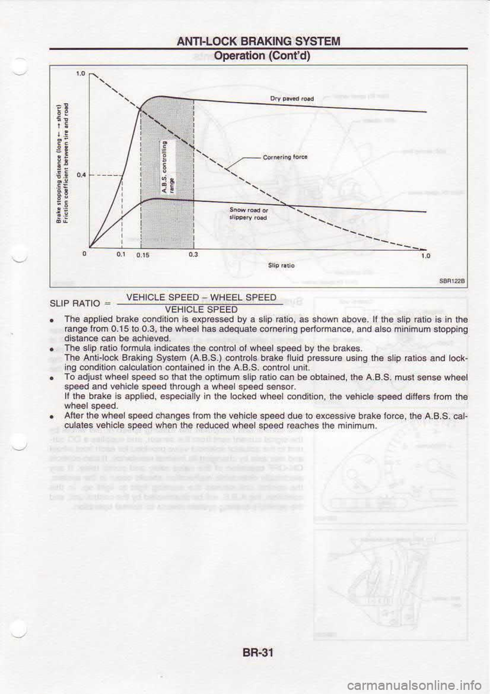
VEHICLE SPEED
. The appll€d bal@ @ndldon ls dp6ssEd by a slip €iio, s shown abova. ll lh€ slip
Etio i6
in th.
€ng€ lom 0.15 lo O.3, tha sh€.| hs ad€quarg coh€ nO p€rloma.@,
and d$ minimum siopplng
distan@ €n b€ achi€v€d.
. Th. srip 6rio lomula indi@r€s rhe @nrrcl ol wheel sp@d by rhe bEk6s.
The Aili-lock Sraklng Sysl€m (A-8.S.)
conlrcls b€k6lluid p@su€
usi.s th. 6lip ratios and lock-
Ing @ndlllon @lculaid ontain€d in rh. A.B-S. control unit.
. To adjusl whel sp€.d so lhrr fi6 oprinum 3lip htio
6 b. obiain.d, th. a,a.s, musi s6ns6 wh4l
3p4d sd v€hiolE sp.6d lhrcugh
a wh*l
.pe€d 5en6or.
ll lha bak
i6
appli€d, €speclally in lhe l@ked wh66l condirion, tE whicl6 sp@d
difi€c fom
th€
. All€r
lh6 wh€.| sp€6d chang€. l@n
th€ vohicle
sp*d due to ex@$lve brake for€, th6 A.B.S. dL
culat€s Ehicle.oe€d when lhe €du@d wh@l so4d @ch6s thB minimum.
VEHICLE
SPEED -
WHEEL SPEED
BB-€1
Page 906 of 1254
ANI}LOCK
BRAKING
SYSTEM
System Components
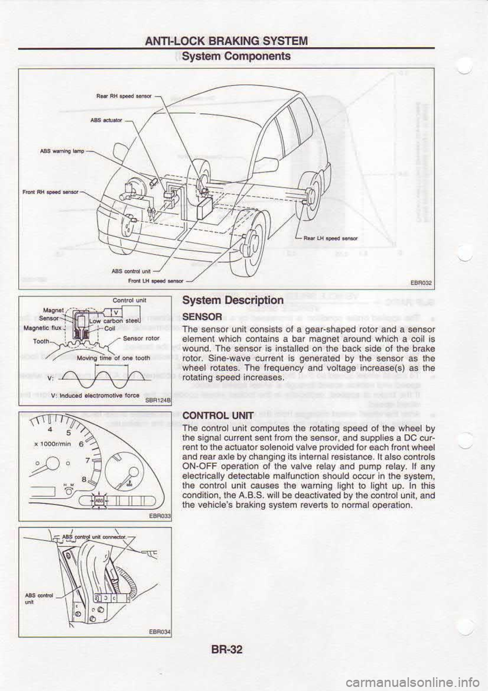
System Descriplion
SENSOF
Th6 sercof unil corcbb ol6 q€aFshgp.d
blor.nd a sensor
alamenl which
conlain6 a bar magnel
around which a coil is
wound. The sener is insialled on the back side ot lh6 b€k€
rotor. sin6'wav€ curent is g.neEted
by lhe sn.or a5 lhe
wh€€l rolale6.
Th. l@quency
and vollage inc€ase(s) as lhe
eialina speed inc€ases,
CONTBOL UNIT
Th. @ntrc! unit computes the oiating speed ol ihe wheet by
ihe siqnalcunentsenl fbn the *nsor, and supples a Dc cur
renl lo the a.iuaior solenoid valve provided
lor each lonr whe6l
and rear a e by cha.g ng its intemal resisla.€. ll also @ntrcl.
ON-OFF operaiion oi the valve rclay and pump
r6lay. ll any
6l6crric.lly d.reciable malluncrion
sholld odur in the system,
ihe contDl unir €uses the waning liqhr ro light up. In lhE
conditio., lhe A.B.S. wil be deaclival.d bv lh6 @ntrol
unt, and
the v6h cls s b€king sr€l€m r6v6ns
b noma
opeElion,
BR-32
Page 907 of 1254
AI{T|.LOCK
BRAKING SYSIEII
System De€crlplion (Coni'd)
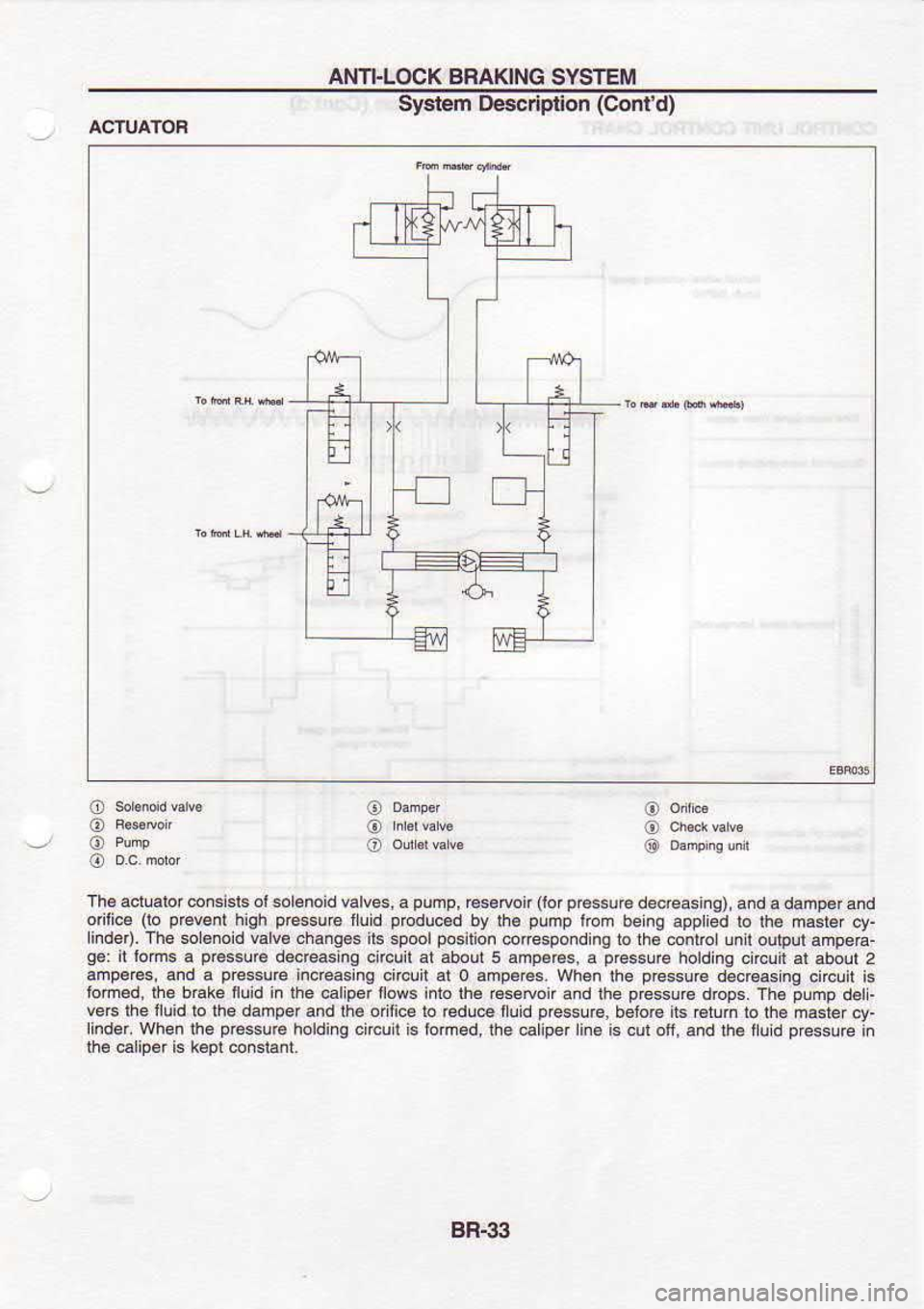
ACTUATOR
o
@
@
@
o
o
o
o
J@
@
Th6 actuslor consisrs
or solenoid valves, a pump,
rcs.tron (brp€ssuB
decreasi.g), a.d adamperand
orilice (lo
pevent
hrgh pressu
6 llud pEouced
bv fe oLnp lron oeng appked to rh€ n4t€r
ct-
nd6r). rh6
$l€rod wlv. +.rqe6 it6
6poolpos'hon @respoad ns ro rr€ 6ntbtunt
oubut amperr-
q.: il lom6
a p€56!@
decreaslng circuit at abour 5 amp6e6.
a pfesure
holding onclir al aboul 2
amp€Fs, and a p@ssure
Increasing circuit 51 0 amp6res.
when ihe p€ssurc
d€crcas no cn@t is
tom€d, |he bdke fuld in the @liperflows inlo lh6 €sedoir
a.d lhe pG$!re
drops- Th6 plmp
d€l-
ve6 lhe iluid lo the dafrper and the odiica
to €du@ tluld
Dre$u@, belorc
irs r6tun ro
lhe m$ter
cv-
hnder. When rh€ p,€surc
holdirq crrcu
I 's
lortred,
fte catrper rin€
is cut of, .nd th€ ,u
d oe$Lre i"
lhe €liod is k€Dl
conslant.
BR-3il
Page 908 of 1254
AI.I]]-LOCK
BRAKING SYSTEM
S'yslern De6cription (Cont
d)
CONTBOL UNTI CONTFOL CHART
a
BR-34
Page 909 of 1254
AI,ITI.LOCK
BRAICNG SYSTEM
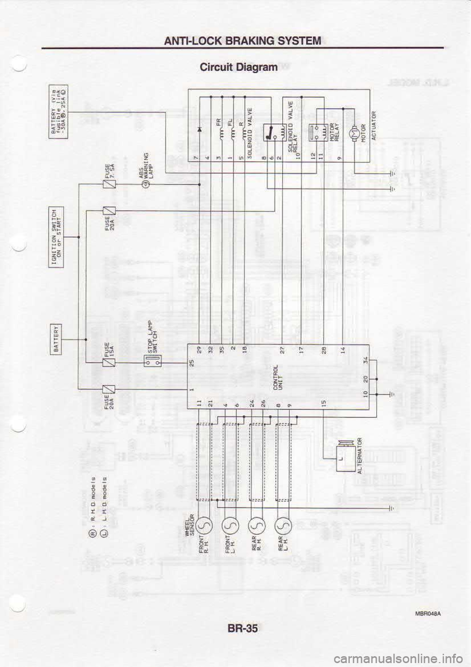
Circuit Dieg|?m
5
e
as
tt
@o Z, Z, at
E; E: ** 9-
6a
EE
;!
T ai
BR€5
Page 910 of 1254
ANTI-LOCK
BRAKING
SYSTEM
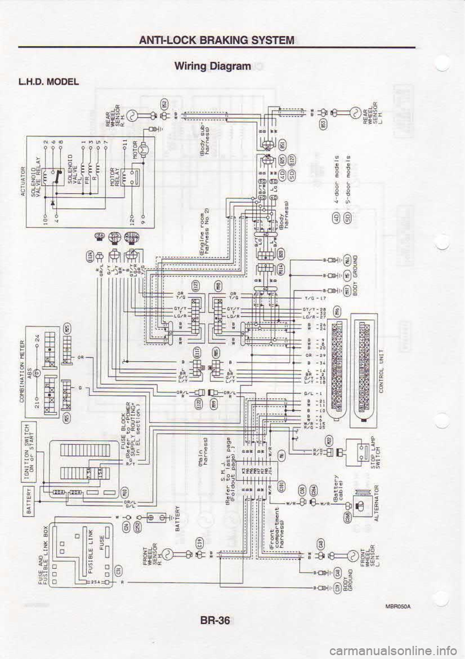
Wiring Diagram
Lh.D MODEL
r30
-a
ng;-
3:
@r'6q
sr'e:
*€E
@€)
F:
35
;!
PI :e
@
e
o
il
)-j:'-:q5
'''d6"'' @
+,,"91e €)
(A
la
€
*'g
{:
'"2
!-@r'i
@ 6
6)
rs
--E
at9
f 4". .E
6r
'i
I
I
E @@@
e+ ffiffil
l-
e
ffil
lffii ffi
t .oi Gl e
i$i I6JBE
u!:
"ng
.I
t!
8R.36
Trending: water pump, radio, oil level, stop start, oil temperature, change time, ESP

![NISSAN SERENA 1993 Service Repair Manual AI.I]]-LOCK
BRAKING SYSTEM
Syslern De6cription (Cont
d)
CONTBOL UNTI CONTFOL CHART
a
BR-34 NISSAN SERENA 1993 Service Repair Manual AI.I]]-LOCK
BRAKING SYSTEM
Syslern De6cription (Cont
d)
CONTBOL UNTI CONTFOL CHART
a
BR-34](/img/5/57387/w960_57387-907.png)
