battery location NISSAN TEANA 2008 Owner's Manual
[x] Cancel search | Manufacturer: NISSAN, Model Year: 2008, Model line: TEANA, Model: NISSAN TEANA 2008Pages: 5121, PDF Size: 69.03 MB
Page 2055 of 5121
![NISSAN TEANA 2008 Owners Manual EXL-26
< FUNCTION DIAGNOSIS >[XENON TYPE]
EXTERIOR LAMP BATTERY SAVER SYSTEM
Component Parts Location
INFOID:0000000003773545
Component DescriptionINFOID:0000000003773546
1. Combination switch 2. IPDM](/img/5/57391/w960_57391-2054.png "NISSAN TEANA 2008 Owners Manual EXL-26
< FUNCTION DIAGNOSIS >[XENON TYPE]
EXTERIOR LAMP BATTERY SAVER SYSTEM
Component Parts Location
INFOID:0000000003773545
Component DescriptionINFOID:0000000003773546
1. Combination switch 2. IPDM")
EXL-26
< FUNCTION DIAGNOSIS >[XENON TYPE]
EXTERIOR LAMP BATTERY SAVER SYSTEM
Component Parts Location
INFOID:0000000003773545
Component DescriptionINFOID:0000000003773546
1. Combination switch 2. IPDM E/R 3. BCM
A. Engine room (LH) B. Behind the combination meter
JPLIA1124ZZ
Part Description
BCM Detects each switch condition by the combination switch reading function.
Activates the battery saver to turn the exterior lamps OFF according to the vehicle
condition.
- Requests each relay OFF to IPDM E/R (with CAN communication).
IPDM E/RControls the integrated relay according to the request from BCM (with CAN communi-
cation).
Combination switch
(Lighting & turn signal switch)Refer to BCS-8, "
System Diagram".
Page 2080 of 5121
![NISSAN TEANA 2008 Owners Manual POWER SUPPLY AND GROUND CIRCUIT
EXL-51
< COMPONENT DIAGNOSIS >[XENON TYPE]
C
D
E
F
G
H
I
J
K
MA
B
EXL
N
O
P
Is the fuse fusing?
YES >> Replace the blown fuse or fusible link after repairing the affect](/img/5/57391/w960_57391-2079.png "NISSAN TEANA 2008 Owners Manual POWER SUPPLY AND GROUND CIRCUIT
EXL-51
< COMPONENT DIAGNOSIS >[XENON TYPE]
C
D
E
F
G
H
I
J
K
MA
B
EXL
N
O
P
Is the fuse fusing?
YES >> Replace the blown fuse or fusible link after repairing the affect")
POWER SUPPLY AND GROUND CIRCUIT
EXL-51
< COMPONENT DIAGNOSIS >[XENON TYPE]
C
D
E
F
G
H
I
J
K
MA
B
EXL
N
O
P
Is the fuse fusing?
YES >> Replace the blown fuse or fusible link after repairing the affected circuit if a fuse or fusible link is
blown.
NO >> GO TO 2.
2.CHECK POWER SUPPLY CIRCUIT
1. Turn ignition switch OFF.
2. Disconnect IPDM E/R connector.
3. Check voltage between IPDM E/R harness connector and ground.
Is the measurement value normal?
YES >> GO TO 3.
NO >> Repair harness or connector.
3.CHECK GROUND CIRCUIT
Check continuity between IPDM E/R harness connectors and ground.
Does continuity exist?
YES >> INSPECTION END
NO >> Repair harness or connector.
AUTO LEVELIZER CONTROL UNIT
AUTO LEVELIZER CONTROL UNIT : Diagnosis ProcedureINFOID:0000000003774348
1.CHECK FUSES
Check that any of the following fuses are fusing
Is the fuse fusing?
YES >> Repair the applicable circuit. And then replace the fuse.
NO >> GO TO 2.
2.CHECK POWER SUPPLY CIRCUIT
1. Turn the ignition switch OFF.
2. Disconnect auto levelizer control unit connector.
3. Turn the ignition switch ON.
4. Check voltage between auto levelizer control unit harness connector and ground.
Signal name Fuses and fusible link No.
Battery power supplyE
50
51
Te r m i n a l s
Voltag e
(Approx.) (+)
(−)
IPDM E/R
Connector Terminal
Ground
E9 1 Battery voltage
IPDM E/R
GroundContinuity
Connector Terminal
E10 12
Existed
E11 41
Signal name Location Fuse No. Capacity
Ignition power supply Fuse block (J/B) 3 10A
Page 2103 of 5121
![NISSAN TEANA 2008 Owners Manual EXL-74
< COMPONENT DIAGNOSIS >[XENON TYPE]
TAIL LAMP CIRCUIT
TAIL LAMP CIRCUIT
Component Function CheckINFOID:0000000003773578
NOTE:
Check the license plate lamp circuit if the tail lamp and the licen](/img/5/57391/w960_57391-2102.png "NISSAN TEANA 2008 Owners Manual EXL-74
< COMPONENT DIAGNOSIS >[XENON TYPE]
TAIL LAMP CIRCUIT
TAIL LAMP CIRCUIT
Component Function CheckINFOID:0000000003773578
NOTE:
Check the license plate lamp circuit if the tail lamp and the licen")
EXL-74
< COMPONENT DIAGNOSIS >[XENON TYPE]
TAIL LAMP CIRCUIT
TAIL LAMP CIRCUIT
Component Function CheckINFOID:0000000003773578
NOTE:
Check the license plate lamp circuit if the tail lamp and the license plate lamp are not turned ON. Refer to EXL-
76, "Component Function Check".
1.CHECK TAIL LAMP OPERATION
IPDM E/R AUTO ACTIVE TEST
1. Activate IPDM E/R auto active test. Refer to PCS-11, "
Diagnosis Description".
2. Check that the tail lamp is turned ON.
CONSULT-III ACTIVE TEST
1. Select “EXTERNAL LAMPS” of IPDM E/R active test item.
2. With operating the test items, check that the tail lamp is turned ON.
Is the tail lamp turned ON?
YES >> Tail lamp circuit is normal.
NO >> Refer to EXL-74, "
Diagnosis Procedure".
Diagnosis ProcedureINFOID:0000000003773579
1.CHECK TAIL LAMP FUSE
1. Turn the ignition switch OFF.
2. Check that the following fuses are not fusing.
Is the fuse fusing?
YES >> Repair the malfunctioning part before replacing the fuse.
NO >> GO TO 2.
2.CHECK TAIL LAMP OUTPUT VOLTAGE
CONSULT-III ACTIVE TEST
1. Disconnect the rear combination lamp connector.
2. Turn the ignition switch ON.
3. Select “EXTERNAL LAMPS” of IPDM E/R active test item.
4. With operating the test items, check the voltage between the IPDM E/R harness connector and the
ground.
Is the measurement value normal?
YES >> GO TO 3.
NO >> Replace IPDM E/R.
3.CHECK TAIL LAMP OPEN CIRCUIT
1. Turn the ignition switch OFF.TAIL : Tail Lamp ON
Off : Tail lamp OFF
Unit Location Fuse No. Capacity
Tail lamp IPDM E/R #53 10 A
Te r m i n a l s
Te s t i t e m
Voltag e
(Approx.) (+) (−)
IPDM E/R
GroundEXTERNAL
LAMPS
Connector Terminal
E10 7TA I LBattery volt-
age
Off 0 V
Page 2232 of 5121
![NISSAN TEANA 2008 Owners Manual AUTO LIGHT SYSTEM
EXL-203
< FUNCTION DIAGNOSIS >[HALOGEN TYPE]
C
D
E
F
G
H
I
J
K
MA
B
EXL
N
O
P
Turns the exterior lamp OFF with the ignition switch ACC or the light switch OFF.
*: The preset time i](/img/5/57391/w960_57391-2231.png "NISSAN TEANA 2008 Owners Manual AUTO LIGHT SYSTEM
EXL-203
< FUNCTION DIAGNOSIS >[HALOGEN TYPE]
C
D
E
F
G
H
I
J
K
MA
B
EXL
N
O
P
Turns the exterior lamp OFF with the ignition switch ACC or the light switch OFF.
*: The preset time i")
AUTO LIGHT SYSTEM
EXL-203
< FUNCTION DIAGNOSIS >[HALOGEN TYPE]
C
D
E
F
G
H
I
J
K
MA
B
EXL
N
O
P
Turns the exterior lamp OFF with the ignition switch ACC or the light switch OFF.
*: The preset time is 45 seconds. The timer operating time can be set by CONSULT-III. Refer to EXL-215,
"HEADLAMP : CONSULT-III Function (BCM - HEAD LAMP)".
NOTE:
When any position other than the light switch AUTO is set, the auto light system function switches to the exte-
rior lamp battery saver function.
Component Parts LocationINFOID:0000000003894283
Component DescriptionINFOID:0000000003894284
1. Combination switch 2. Optical sensor 3. IPDM E/R
4. BCM
A. Instrument upper panel (RH) B. Engine room (LH) C. Behind the combination meter
J P L I A 111 9 Z Z
Part Description
BCM Detects each switch condition by the combination switch reading function.
Judges the outside brightness from the optical sensor signal.
Judges the OFF timing according to the vehicle condition.
Judges the ON/OFF status of the exterior lamp and each illumination according to the
outside brightness and the vehicle condition.
Requests ON/OFF of each relay to IPDM E/R (with CAN communication).
IPDM E/RControls the integrated relay, and supplies voltage to the load according to the request
from BCM (with CAN communication).
Combination switch
(Lighting & turn signal switch)Refer to BCS-8, "
System Diagram".
Optical sensor Refer to EXL-238, "
Description".
Page 2242 of 5121
![NISSAN TEANA 2008 Owners Manual EXTERIOR LAMP BATTERY SAVER SYSTEM
EXL-213
< FUNCTION DIAGNOSIS >[HALOGEN TYPE]
C
D
E
F
G
H
I
J
K
MA
B
EXL
N
O
P
Component Parts LocationINFOID:0000000003894303
Component DescriptionINFOID:00000000038](/img/5/57391/w960_57391-2241.png "NISSAN TEANA 2008 Owners Manual EXTERIOR LAMP BATTERY SAVER SYSTEM
EXL-213
< FUNCTION DIAGNOSIS >[HALOGEN TYPE]
C
D
E
F
G
H
I
J
K
MA
B
EXL
N
O
P
Component Parts LocationINFOID:0000000003894303
Component DescriptionINFOID:00000000038")
EXTERIOR LAMP BATTERY SAVER SYSTEM
EXL-213
< FUNCTION DIAGNOSIS >[HALOGEN TYPE]
C
D
E
F
G
H
I
J
K
MA
B
EXL
N
O
P
Component Parts LocationINFOID:0000000003894303
Component DescriptionINFOID:0000000003894304
1. Combination switch 2. IPDM E/R 3. BCM
A. Engine room (LH) B. Behind the combination meter
JPLIA1124ZZ
Part Description
BCM Detects each switch condition by the combination switch reading function.
Activates the battery saver to turn the exterior lamps OFF according to the vehicle
condition.
- Requests each relay OFF to IPDM E/R (with CAN communication).
IPDM E/RControls the integrated relay according to the request from BCM (with CAN communi-
cation).
Combination switch
(Lighting & turn signal switch)Refer to BCS-8, "
System Diagram".
Page 2272 of 5121
![NISSAN TEANA 2008 Owners Manual TAIL LAMP CIRCUIT
EXL-243
< COMPONENT DIAGNOSIS >[HALOGEN TYPE]
C
D
E
F
G
H
I
J
K
MA
B
EXL
N
O
P
TAIL LAMP CIRCUIT
Component Function CheckINFOID:0000000003894331
NOTE:
Check the license plate lamp ci](/img/5/57391/w960_57391-2271.png "NISSAN TEANA 2008 Owners Manual TAIL LAMP CIRCUIT
EXL-243
< COMPONENT DIAGNOSIS >[HALOGEN TYPE]
C
D
E
F
G
H
I
J
K
MA
B
EXL
N
O
P
TAIL LAMP CIRCUIT
Component Function CheckINFOID:0000000003894331
NOTE:
Check the license plate lamp ci")
TAIL LAMP CIRCUIT
EXL-243
< COMPONENT DIAGNOSIS >[HALOGEN TYPE]
C
D
E
F
G
H
I
J
K
MA
B
EXL
N
O
P
TAIL LAMP CIRCUIT
Component Function CheckINFOID:0000000003894331
NOTE:
Check the license plate lamp circuit if the tail lamp and the license plate lamp are not turned ON. Refer to EXL-
245, "Component Function Check".
1.CHECK TAIL LAMP OPERATION
IPDM E/R AUTO ACTIVE TEST
1. Activate IPDM E/R auto active test. Refer to PCS-11, "
Diagnosis Description".
2. Check that the tail lamp is turned ON.
CONSULT-III ACTIVE TEST
1. Select “EXTERNAL LAMPS” of IPDM E/R active test item.
2. With operating the test items, check that the tail lamp is turned ON.
Is the tail lamp turned ON?
YES >> Tail lamp circuit is normal.
NO >> Refer to EXL-243, "
Diagnosis Procedure".
Diagnosis ProcedureINFOID:0000000003894332
1.CHECK TAIL LAMP FUSE
1. Turn the ignition switch OFF.
2. Check that the following fuses are not fusing.
Is the fuse fusing?
YES >> Repair the malfunctioning part before replacing the fuse.
NO >> GO TO 2.
2.CHECK TAIL LAMP OUTPUT VOLTAGE
CONSULT-III ACTIVE TEST
1. Disconnect the rear combination lamp connector.
2. Turn the ignition switch ON.
3. Select “EXTERNAL LAMPS” of IPDM E/R active test item.
4. With operating the test items, check the voltage between the IPDM E/R harness connector and the
ground.
Is the measurement value normal?
YES >> GO TO 3.
NO >> Replace IPDM E/R.
3.CHECK TAIL LAMP OPEN CIRCUIT
1. Turn the ignition switch OFF.TAIL : Tail Lamp ON
Off : Tail lamp OFF
Unit Location Fuse No. Capacity
Tail lamp IPDM E/R #53 10 A
Te r m i n a l s
Te s t i t e m
Vo l ta g e
(Approx.) (+) (−)
IPDM E/R
GroundEXTERNAL
LAMPS
Connector Terminal
E10 7TA I LBattery volt-
age
Off 0 V
Page 2390 of 5121

EXT-1
BODY EXTERIOR, DOORS, ROOF & VEHICLE SECURITY
C
D
E
F
G H
I
J
L
M
SECTION EXT
A
B
EXT
N
O P
CONTENTS
EXTERIOR
SYMPTOM DIAGNOSIS ..... ..........................2
SQUEAK AND RATTLE TROUBLE DIAG-
NOSES ........................ ........................................
2
Work Flow ........................................................... ......2
Inspection Procedure ................................................4
Diagnostic Worksheet ...............................................6
PRECAUTION ...............................................8
PRECAUTIONS .............................................. .....8
Precaution for Supplemental Restraint System
(SRS) "AIR BAG" and "SEAT BELT PRE-TEN-
SIONER" ............................................................. ......
8
Precaution Necessary for Steering Wheel Rota-
tion after Battery Disconnect .....................................
8
Precaution for Procedure without Cowl Top Cover ......9
Precaution for Work ..................................................9
PREPARATION ...........................................10
PREPARATION .............................................. ....10
Commercial Service Tools ................................. ....10
ON-VEHICLE REPAIR .................................11
FRONT BUMPER ........................................... ....11
Exploded View .................................................... ....11
Removal and Installation .........................................12
REAR BUMPER .................................................15
Exploded View .................................................... ....15
Removal and Installation .........................................16
FRONT GRILLE .................................................18
Exploded View .................................................... ....18
Removal and Installation .........................................18
COWL TOP .........................................................20
Exploded View .................................................... ....20
Removal and Installation .........................................20
FENDER PROTECTOR ......................................22
FENDER PROTECTOR ......................................... ....22
FENDER PROTECTOR : Exploded View ...............22
FENDER PROTECTOR : Removal and Installa-
tion ...........................................................................
22
REAR WHEEL HOUSE PROTECTOR .................. ....23
REAR WHEEL HOUSE PROTECTOR : Exploded
View .........................................................................
24
REAR WHEEL HOUSE PROTECTOR : Removal
and Installation ........................................................
24
CENTER MUD GUARD .....................................26
Exploded View .........................................................26
Removal and Installation .........................................26
FLOOR SIDE FAIRING .....................................28
Exploded View .........................................................28
Removal and Installation .........................................28
ROOF SIDE MOLDING .....................................29
Exploded View .........................................................29
Removal and Installation .........................................29
DRIP MOLDING ................................................32
Exploded View .........................................................32
Removal and Installation .........................................32
DOOR OUTSIDE MOLDING .............................33
Exploded View .........................................................33
Removal and Installation .........................................33
DOOR PARTING SEAL ....................................35
Exploded View .........................................................35
Removal and Installation .........................................35
SIDE GUARD MOLDING ..................................36
Component Parts Location .................................. ....36
Removal and Installation .........................................36
TRUNK LID FINISHER ......................................38
Exploded View .........................................................38
Removal and Installation .........................................38
Page 2431 of 5121
PRECAUTIONS
FAX-3
< PRECAUTION >
C
E
F
G
H
I
J
K
L
MA
B
FA X
N
O
P
PRECAUTION
PRECAUTIONS
Precaution for Supplemental Restraint System (SRS) "AIR BAG" and "SEAT BELT
PRE-TENSIONER"
INFOID:0000000003890158
The Supplemental Restraint System such as “AIR BAG” and “SEAT BELT PRE-TENSIONER”, used along
with a front seat belt, helps to reduce the risk or severity of injury to the driver and front passenger for certain
types of collision. Information necessary to service the system safely is included in the “SRS AIRBAG” and
“SEAT BELT” of this Service Manual.
WARNING:
• To avoid rendering the SRS inoperative, which could increase the risk of personal injury or death in
the event of a collision which would result in air bag inflation, all maintenance must be performed by
an authorized NISSAN/INFINITI dealer.
Improper maintenance, including incorrect removal and installation of the SRS, can lead to personal
injury caused by unintentional activation of the system. For removal of Spiral Cable and Air Bag
Module, see the “SRS AIRBAG”.
Never use electrical test equipment on any circuit related to the SRS unless instructed to in this Ser-
vice Manual. SRS wiring harnesses can be identified by yellow and/or orange harnesses or harness
connectors.
Precaution Necessary for Steering Wheel Rotation after Battery Disconnect
INFOID:0000000003890159
NOTE:
Before removing and installing any control units, first turn the push-button ignition switch to the LOCK posi-
tion, then disconnect both battery cables.
After finishing work, confirm that all control unit connectors are connected properly, then re-connect both
battery cables.
Always use CONSULT-III to perform self-diagnosis as a part of each function inspection after finishing work.
If a DTC is detected, perform trouble diagnosis according to self-diagnosis results.
This vehicle is equipped with a push-button ignition switch and a steering lock unit.
If the battery is disconnected or discharged, the steering wheel will lock and cannot be turned.
If turning the steering wheel is required with the battery disconnected or discharged, follow the procedure
below before starting the repair operation.
OPERATION PROCEDURE
1. Connect both battery cables.
NOTE:
Supply power using jumper cables if battery is discharged.
2. Turn the push-button ignition switch to ACC position.
(At this time, the steering lock will be released.)
3. Disconnect both battery cables. The steering lock will remain released with both battery cables discon-
nected and the steering wheel can be turned.
4. Perform the necessary repair operation.
5. When the repair work is completed, re-connect both battery cables. With the brake pedal released, turn
the push-button ignition switch from ACC position to ON position, then to LOCK position. (The steering
wheel will lock when the push-button ignition switch is turned to LOCK position.)
6. Perform self-diagnosis check of all control units using CONSULT-III.
Precautions for Drive ShaftINFOID:0000000003811071
CAUTION:
Note the following precautions when disassembling and assembling drive shaft.
Never disassemble joint sub-assembly because it is non-overhaul parts.
Perform work in a dust-free location.
Before disassembling and assembling, clean the parts.
Prevent the entry of foreign objects during disassembly of the service location.
Page 2499 of 5121
GI-6
< HOW TO USE THIS MANUAL >
HOW TO FOLLOW TROUBLE DIAGNOSES
HOW TO FOLLOW TROUBLE DIAGNOSES
DescriptionINFOID:0000000003852763
NOTICE:
Trouble diagnoses indicate work procedures required to diagnose problems effectively. Observe the following
instructions before diagnosing.
Before performing trouble diagnoses, read the “Work Flow” in each section.
After repairs, re-check that the problem has been completely eliminated.
Refer to Component Parts and Harness Connector Location for the Systems described in each section for
identification/location of components and harness connectors.
When checking circuit continuity, ignition switch should be OFF.
Refer to the Circuit Diagram for quick pinpoint check.
If you need to check circuit continuity between harness connectors in more detail, such as when a sub-har-
ness is used, refer to Wiring Diagram in each individual section and Harness Layout in PG section for identi-
fication of harness connectors.
Before checking voltage at connectors, check battery voltage.
After accomplishing the Diagnosis Procedures and Electrical Components Inspection, make sure that all
harness connectors are reconnected as they were.
How to Follow Test Groups in Trouble DiagnosisINFOID:0000000003852764
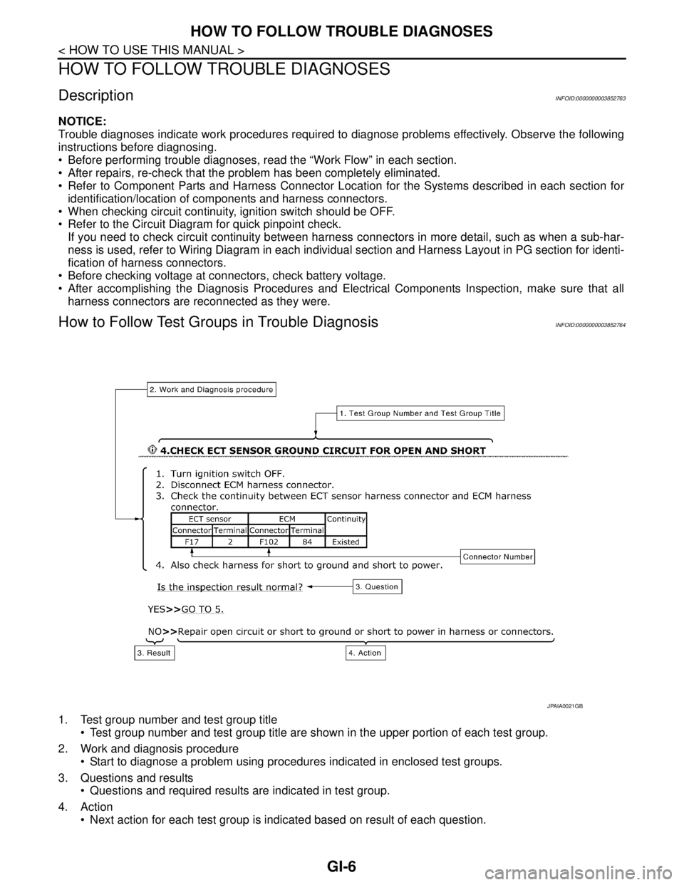
1. Test group number and test group title
Test group number and test group title are shown in the upper portion of each test group.
2. Work and diagnosis procedure
Start to diagnose a problem using procedures indicated in enclosed test groups.
3. Questions and results
Questions and required results are indicated in test group.
4. Action
Next action for each test group is indicated based on result of each question.
JPAIA0021GB
Page 2519 of 5121
GI-26
< PRECAUTION >
PRECAUTIONS
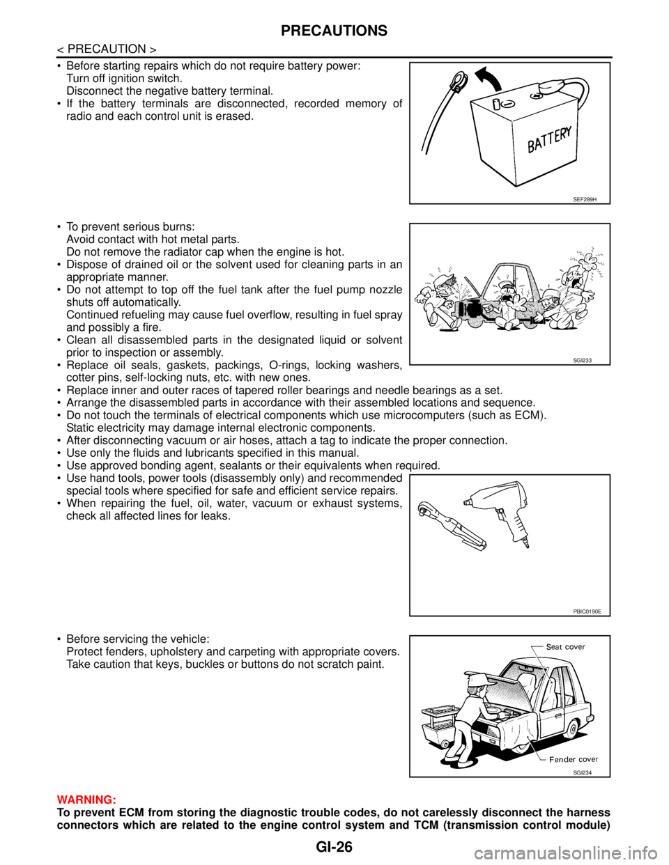
Before starting repairs which do not require battery power:
Turn off ignition switch.
Disconnect the negative battery terminal.
If the battery terminals are disconnected, recorded memory of
radio and each control unit is erased.
To prevent serious burns:
Avoid contact with hot metal parts.
Do not remove the radiator cap when the engine is hot.
Dispose of drained oil or the solvent used for cleaning parts in an
appropriate manner.
Do not attempt to top off the fuel tank after the fuel pump nozzle
shuts off automatically.
Continued refueling may cause fuel overflow, resulting in fuel spray
and possibly a fire.
Clean all disassembled parts in the designated liquid or solvent
prior to inspection or assembly.
Replace oil seals, gaskets, packings, O-rings, locking washers,
cotter pins, self-locking nuts, etc. with new ones.
Replace inner and outer races of tapered roller bearings and needle bearings as a set.
Arrange the disassembled parts in accordance with their assembled locations and sequence.
Do not touch the terminals of electrical components which use microcomputers (such as ECM).
Static electricity may damage internal electronic components.
After disconnecting vacuum or air hoses, attach a tag to indicate the proper connection.
Use only the fluids and lubricants specified in this manual.
Use approved bonding agent, sealants or their equivalents when required.
Use hand tools, power tools (disassembly only) and recommended
special tools where specified for safe and efficient service repairs.
When repairing the fuel, oil, water, vacuum or exhaust systems,
check all affected lines for leaks.
Before servicing the vehicle:
Protect fenders, upholstery and carpeting with appropriate covers.
Take caution that keys, buckles or buttons do not scratch paint.
WARNING:
To prevent ECM from storing the diagnostic trouble codes, do not carelessly disconnect the harness
connectors which are related to the engine control system and TCM (transmission control module)
SEF289H
SGI233
PBIC0190E
SGI234