Water drain plug NISSAN TEANA 2008 Service Manual
[x] Cancel search | Manufacturer: NISSAN, Model Year: 2008, Model line: TEANA, Model: NISSAN TEANA 2008Pages: 5121, PDF Size: 69.03 MB
Page 1131 of 5121
CO-8
< ON-VEHICLE MAINTENANCE >
ENGINE COOLANT
ON-VEHICLE MAINTENANCE
ENGINE COOLANT
InspectionINFOID:0000000003793166
LEVEL
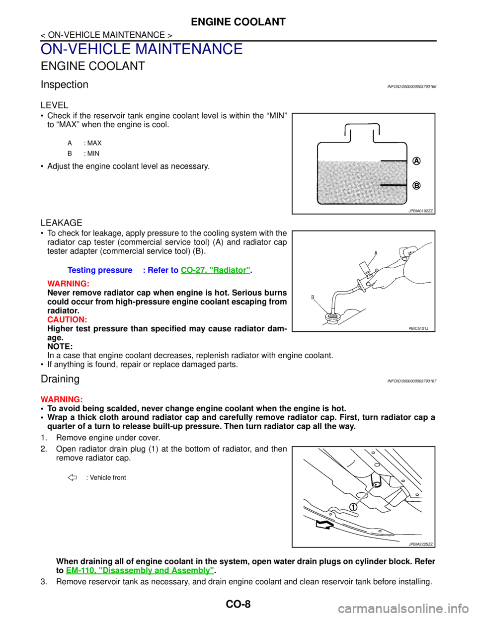
Check if the reservoir tank engine coolant level is within the “MIN”
to “MAX” when the engine is cool.
Adjust the engine coolant level as necessary.
LEAKAGE
To check for leakage, apply pressure to the cooling system with the
radiator cap tester (commercial service tool) (A) and radiator cap
tester adapter (commercial service tool) (B).
WARNING:
Never remove radiator cap when engine is hot. Serious burns
could occur from high-pressure engine coolant escaping from
radiator.
CAUTION:
Higher test pressure than specified may cause radiator dam-
age.
NOTE:
In a case that engine coolant decreases, replenish radiator with engine coolant.
If anything is found, repair or replace damaged parts.
DrainingINFOID:0000000003793167
WARNING:
To avoid being scalded, never change engine coolant when the engine is hot.
Wrap a thick cloth around radiator cap and carefully remove radiator cap. First, turn radiator cap a
quarter of a turn to release built-up pressure. Then turn radiator cap all the way.
1. Remove engine under cover.
2. Open radiator drain plug (1) at the bottom of radiator, and then
remove radiator cap.
When draining all of engine coolant in the system, open water drain plugs on cylinder block. Refer
to EM-110, "
Disassembly and Assembly".
3. Remove reservoir tank as necessary, and drain engine coolant and clean reservoir tank before installing.
A: MAX
B: MIN
JPBIA0102ZZ
Testing pressure : Refer to CO-27, "Radiator".
PBIC5121J
: Vehicle front
JPBIA2225ZZ
Page 1132 of 5121
ENGINE COOLANT
CO-9
< ON-VEHICLE MAINTENANCE >
C
D
E
F
G
H
I
J
K
L
MA
CO
N
P O
4. Check drained engine coolant for contaminants such as rust, corrosion or discoloration.
If contaminated, flush the engine cooling system. Refer to CO-10, "
Flushing".
RefillingINFOID:0000000003793168
1. Install reservoir tank if removed, and radiator drain plug.
CAUTION:
Be sure to clean drain plug and install with new O-ring.
If water drain plugs on cylinder block are removed, close and tighten them. Refer to EM-110, "
Dis-
assembly and Assembly".
2. Check that each hose clamp has been firmly tightened.
3. Remove air duct assembly and air cleaner cases (upper and lower) assembly. Refer to EM-26, "
Exploded
View".
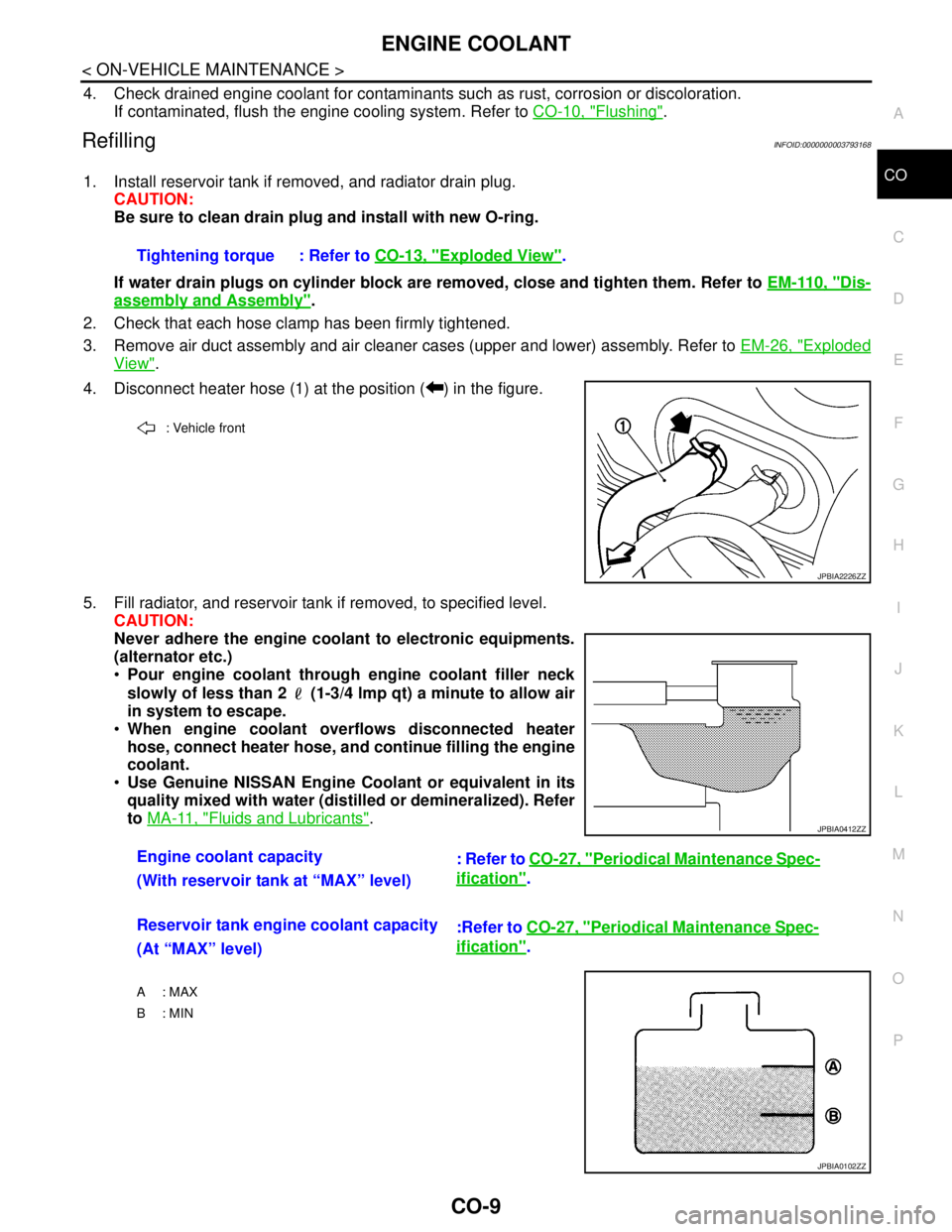
4. Disconnect heater hose (1) at the position ( ) in the figure.
5. Fill radiator, and reservoir tank if removed, to specified level.
CAUTION:
Never adhere the engine coolant to electronic equipments.
(alternator etc.)
Pour engine coolant through engine coolant filler neck
slowly of less than 2 (1-3/4 lmp qt) a minute to allow air
in system to escape.
When engine coolant overflows disconnected heater
hose, connect heater hose, and continue filling the engine
coolant.
Use Genuine NISSAN Engine Coolant or equivalent in its
quality mixed with water (distilled or demineralized). Refer
to MA-11, "
Fluids and Lubricants". Tightening torque : Refer to CO-13, "
Exploded View".
: Vehicle front
JPBIA2226ZZ
Engine coolant capacity
: Refer to CO-27, "Periodical Maintenance Spec-
ification".
(With reservoir tank at “MAX” level)
Reservoir tank engine coolant capacity
:Refer to CO-27, "
Periodical Maintenance Spec-
ification".
(At “MAX” level)
A : MAX
B: MIN
JPBIA0412ZZ
JPBIA0102ZZ
Page 1133 of 5121
CO-10
< ON-VEHICLE MAINTENANCE >
ENGINE COOLANT
6. Install air duct assembly and air cleaner cases (upper and lower) assembly. Refer to EM-26, "Exploded
View".
7. Install radiator cap.
8. Warm up engine until opening thermostat. Standard for warming-up time is approximately 10 minutes at
3,000 rpm.
Check thermostat opening condition by touching radiator hose (lower) to see a flow of warm water.
CAUTION:
Watch water temperature gauge so as not to overheat engine.
9. Stop the engine and cool down to less than approximately 50°C (122°F).
Cool down using fan to reduce the time.
If necessary, refill radiator up to filler neck with engine coolant.
CAUTION:
Never adhere the engine coolant to electronic equipments. (alternator etc.)
10. Refill reservoir tank to “MAX” level line with engine coolant.
11. Repeat steps 7 through 10 two or more times with radiator cap installed until engine coolant level no
longer drops.
12. Check cooling system for leakage with engine running.
13. Warm up the engine, and check for sound of engine coolant flow while running engine from idle up to
3,000 rpm with heater temperature controller set at several position between “COOL” and “WARM”.
Sound may be noticeable at heater unit.
14. Repeat step 13 three times.
15. If sound is heard, bleed air from cooling system by repeating step 5, and steps from 7 to 14 until engine
coolant level no longer drops.
FlushingINFOID:0000000003793169
1. Install reservoir tank if removed, and radiator drain plug.
CAUTION:
Be sure to clean drain plug and install with new O-ring.
If water drain plugs on cylinder block are removed, close and tighten them. Refer to EM-110, "
Dis-
assembly and Assembly".
2. Remove air duct assembly and air cleaner cases (upper and lower) assembly. Refer to EM-26, "
Exploded
View".
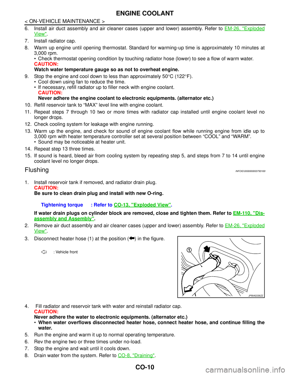
3. Disconnect heater hose (1) at the position ( ) in the figure.
4. Fill radiator and reservoir tank with water and reinstall radiator cap.
CAUTION:
Never adhere the water to electronic equipments. (alternator etc.)
When water overflows disconnected heater hose, connect heater hose, and continue filling the
water.
5. Run the engine and warm it up to normal operating temperature.
6. Rev the engine two or three times under no-load.
7. Stop the engine and wait until it cools down.
8. Drain water from the system. Refer to CO-8, "
Draining". Tightening torque : Refer to CO-13, "
Exploded View".
: Vehicle front
JPBIA2226ZZ
Page 1136 of 5121
RADIATOR
CO-13
< ON-VEHICLE REPAIR >
C
D
E
F
G
H
I
J
K
L
MA
CO
N
P O
ON-VEHICLE REPAIR
RADIATOR
Exploded ViewINFOID:0000000003793172
Removal and InstallationINFOID:0000000003793173
REMOVAL
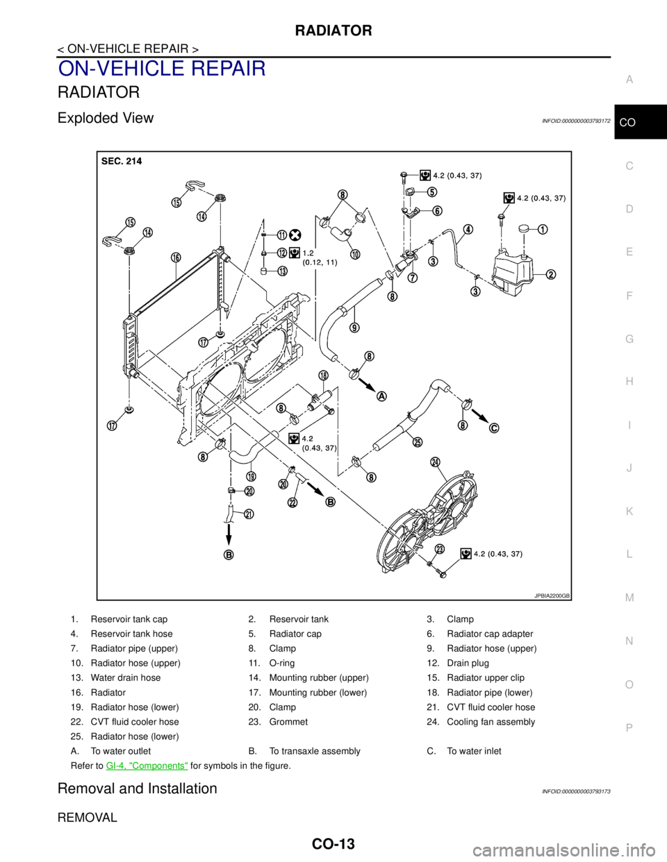
1. Reservoir tank cap 2. Reservoir tank 3. Clamp
4. Reservoir tank hose 5. Radiator cap 6. Radiator cap adapter
7. Radiator pipe (upper) 8. Clamp 9. Radiator hose (upper)
10. Radiator hose (upper) 11. O-ring 12. Drain plug
13. Water drain hose 14. Mounting rubber (upper) 15. Radiator upper clip
16. Radiator 17. Mounting rubber (lower) 18. Radiator pipe (lower)
19. Radiator hose (lower) 20. Clamp 21. CVT fluid cooler hose
22. CVT fluid cooler hose 23. Grommet 24. Cooling fan assembly
25. Radiator hose (lower)
A. To water outlet B. To transaxle assembly C. To water inlet
Refer to GI-4, "
Components" for symbols in the figure.
JPBIA2200GB
Page 1141 of 5121
CO-18
< ON-VEHICLE REPAIR >
WATER PUMP
WATER PUMP
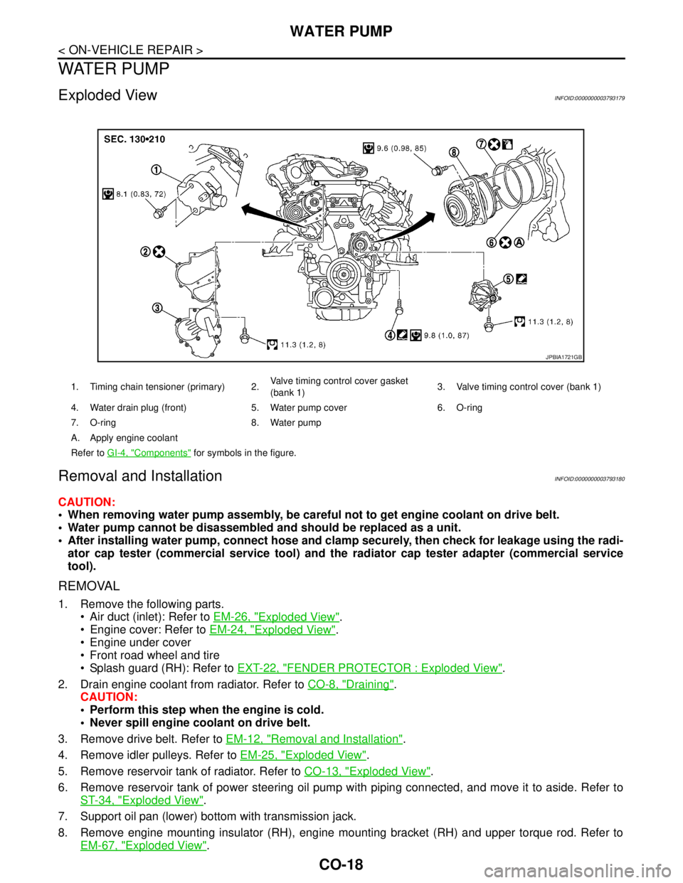
Exploded ViewINFOID:0000000003793179
Removal and InstallationINFOID:0000000003793180
CAUTION:
When removing water pump assembly, be careful not to get engine coolant on drive belt.
Water pump cannot be disassembled and should be replaced as a unit.
After installing water pump, connect hose and clamp securely, then check for leakage using the radi-
ator cap tester (commercial service tool) and the radiator cap tester adapter (commercial service
tool).
REMOVAL
1. Remove the following parts.
Air duct (inlet): Refer to EM-26, "
Exploded View".
Engine cover: Refer to EM-24, "
Exploded View".
Engine under cover
Front road wheel and tire
Splash guard (RH): Refer to EXT-22, "
FENDER PROTECTOR : Exploded View".
2. Drain engine coolant from radiator. Refer to CO-8, "
Draining".
CAUTION:
Perform this step when the engine is cold.
Never spill engine coolant on drive belt.
3. Remove drive belt. Refer to EM-12, "
Removal and Installation".
4. Remove idler pulleys. Refer to EM-25, "
Exploded View".
5. Remove reservoir tank of radiator. Refer to CO-13, "
Exploded View".
6. Remove reservoir tank of power steering oil pump with piping connected, and move it to aside. Refer to
ST-34, "
Exploded View".
7. Support oil pan (lower) bottom with transmission jack.
8. Remove engine mounting insulator (RH), engine mounting bracket (RH) and upper torque rod. Refer to
EM-67, "
Exploded View".
1. Timing chain tensioner (primary) 2.Valve timing control cover gasket
(bank 1)3. Valve timing control cover (bank 1)
4. Water drain plug (front) 5. Water pump cover 6. O-ring
7. O-ring 8. Water pump
A. Apply engine coolant
Refer to GI-4, "
Components" for symbols in the figure.
JPBIA1721GB
Page 1142 of 5121
WATER PUMP
CO-19
< ON-VEHICLE REPAIR >
C
D
E
F
G
H
I
J
K
L
MA
CO
N
P O
9. Remove water drain plug (front) on water pump side of cylinder block to drain engine coolant from engine
inside.
10. Remove valve timing control cover (bank 1) and water pump cover from front timing chain case.
Use the seal cutter [SST: KV10111100 (J37228)] to cut liquid gasket for removal.
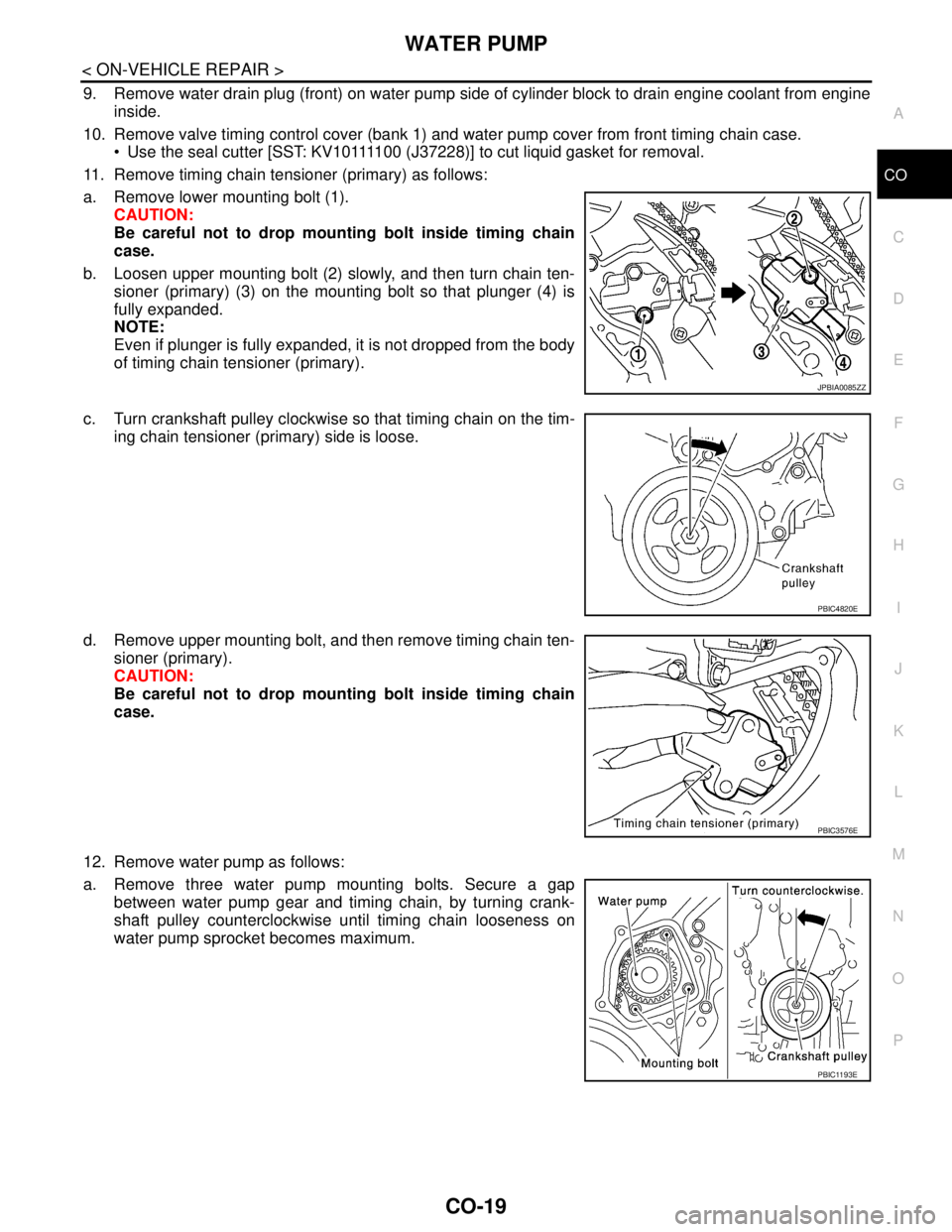
11. Remove timing chain tensioner (primary) as follows:
a. Remove lower mounting bolt (1).
CAUTION:
Be careful not to drop mounting bolt inside timing chain
case.
b. Loosen upper mounting bolt (2) slowly, and then turn chain ten-
sioner (primary) (3) on the mounting bolt so that plunger (4) is
fully expanded.
NOTE:
Even if plunger is fully expanded, it is not dropped from the body
of timing chain tensioner (primary).
c. Turn crankshaft pulley clockwise so that timing chain on the tim-
ing chain tensioner (primary) side is loose.
d. Remove upper mounting bolt, and then remove timing chain ten-
sioner (primary).
CAUTION:
Be careful not to drop mounting bolt inside timing chain
case.
12. Remove water pump as follows:
a. Remove three water pump mounting bolts. Secure a gap
between water pump gear and timing chain, by turning crank-
shaft pulley counterclockwise until timing chain looseness on
water pump sprocket becomes maximum.
JPBIA0085ZZ
PBIC4820E
PBIC3576E
PBIC1193E
Page 1144 of 5121
WATER PUMP
CO-21
< ON-VEHICLE REPAIR >
C
D
E
F
G
H
I
J
K
L
MA
CO
N
P O
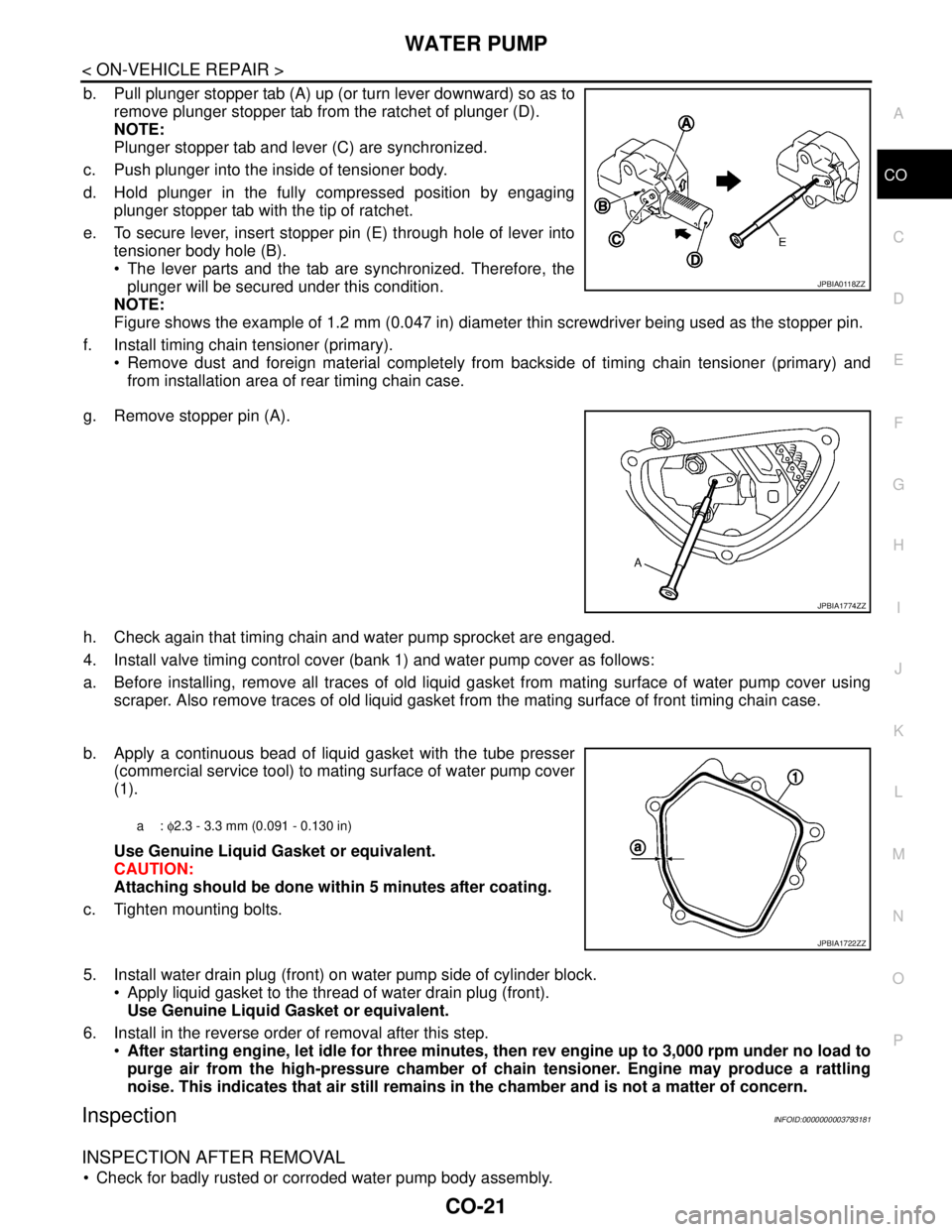
b. Pull plunger stopper tab (A) up (or turn lever downward) so as to
remove plunger stopper tab from the ratchet of plunger (D).
NOTE:
Plunger stopper tab and lever (C) are synchronized.
c. Push plunger into the inside of tensioner body.
d. Hold plunger in the fully compressed position by engaging
plunger stopper tab with the tip of ratchet.
e. To secure lever, insert stopper pin (E) through hole of lever into
tensioner body hole (B).
The lever parts and the tab are synchronized. Therefore, the
plunger will be secured under this condition.
NOTE:
Figure shows the example of 1.2 mm (0.047 in) diameter thin screwdriver being used as the stopper pin.
f. Install timing chain tensioner (primary).
Remove dust and foreign material completely from backside of timing chain tensioner (primary) and
from installation area of rear timing chain case.
g. Remove stopper pin (A).
h. Check again that timing chain and water pump sprocket are engaged.
4. Install valve timing control cover (bank 1) and water pump cover as follows:
a. Before installing, remove all traces of old liquid gasket from mating surface of water pump cover using
scraper. Also remove traces of old liquid gasket from the mating surface of front timing chain case.
b. Apply a continuous bead of liquid gasket with the tube presser
(commercial service tool) to mating surface of water pump cover
(1).
Use Genuine Liquid Gasket or equivalent.
CAUTION:
Attaching should be done within 5 minutes after coating.
c. Tighten mounting bolts.
5. Install water drain plug (front) on water pump side of cylinder block.
Apply liquid gasket to the thread of water drain plug (front).
Use Genuine Liquid Gasket or equivalent.
6. Install in the reverse order of removal after this step.
After starting engine, let idle for three minutes, then rev engine up to 3,000 rpm under no load to
purge air from the high-pressure chamber of chain tensioner. Engine may produce a rattling
noise. This indicates that air still remains in the chamber and is not a matter of concern.
InspectionINFOID:0000000003793181
INSPECTION AFTER REMOVAL
Check for badly rusted or corroded water pump body assembly.
JPBIA0118ZZ
JPBIA1774ZZ
a: φ2.3 - 3.3 mm (0.091 - 0.130 in)
JPBIA1722ZZ
Page 1146 of 5121
WATER INLET AND THERMOSTAT ASSEMBLY
CO-23
< ON-VEHICLE REPAIR >
C
D
E
F
G
H
I
J
K
L
MA
CO
N
P O
WATER INLET AND THERMOSTAT ASSEMBLY
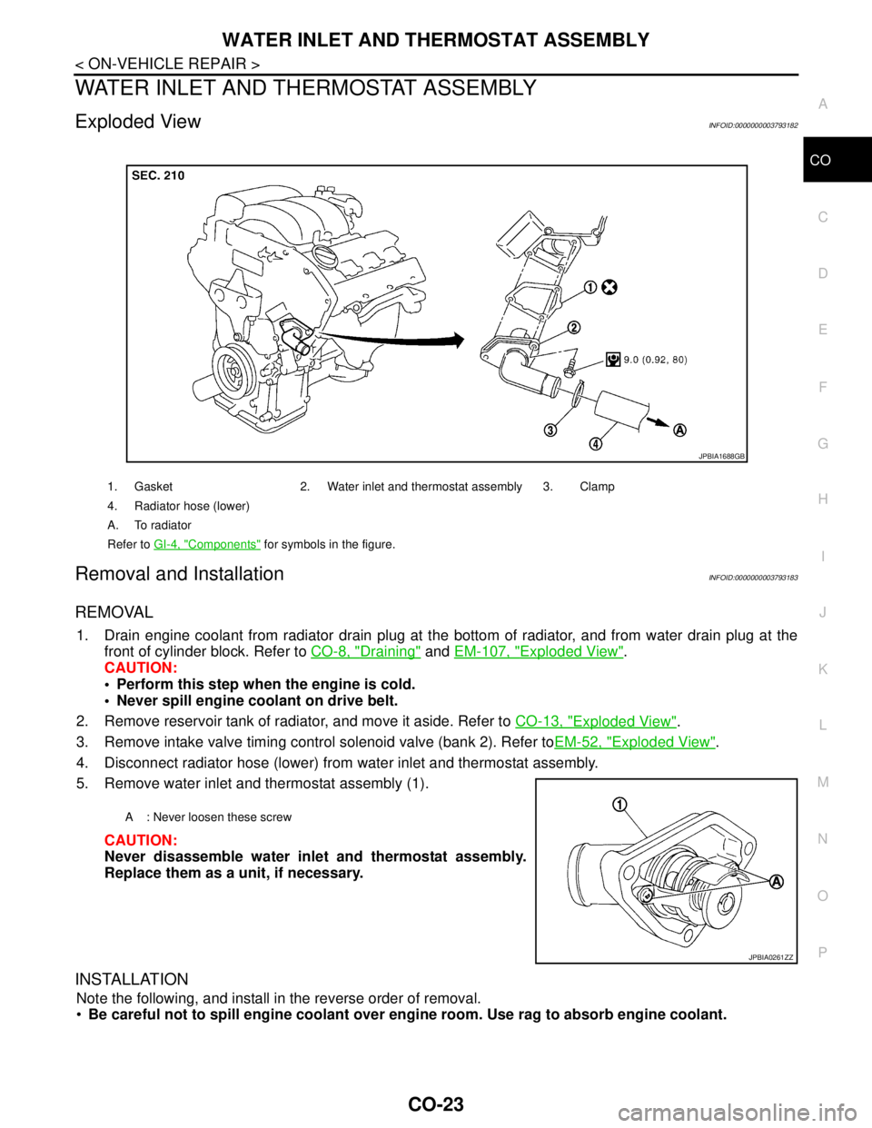
Exploded ViewINFOID:0000000003793182
Removal and InstallationINFOID:0000000003793183
REMOVAL
1. Drain engine coolant from radiator drain plug at the bottom of radiator, and from water drain plug at the
front of cylinder block. Refer to CO-8, "
Draining" and EM-107, "Exploded View".
CAUTION:
Perform this step when the engine is cold.
Never spill engine coolant on drive belt.
2. Remove reservoir tank of radiator, and move it aside. Refer to CO-13, "
Exploded View".
3. Remove intake valve timing control solenoid valve (bank 2). Refer toEM-52, "
Exploded View".
4. Disconnect radiator hose (lower) from water inlet and thermostat assembly.
5. Remove water inlet and thermostat assembly (1).
CAUTION:
Never disassemble water inlet and thermostat assembly.
Replace them as a unit, if necessary.
INSTALLATION
Note the following, and install in the reverse order of removal.
Be careful not to spill engine coolant over engine room. Use rag to absorb engine coolant.
1. Gasket 2. Water inlet and thermostat assembly 3. Clamp
4. Radiator hose (lower)
A. To radiator
Refer to GI-4, "
Components" for symbols in the figure.
JPBIA1688GB
A : Never loosen these screw
JPBIA0261ZZ
Page 1148 of 5121
WATER OUTLET AND WATER PIPING
CO-25
< ON-VEHICLE REPAIR >
C
D
E
F
G
H
I
J
K
L
MA
CO
N
P O
WATER OUTLET AND WATER PIPING
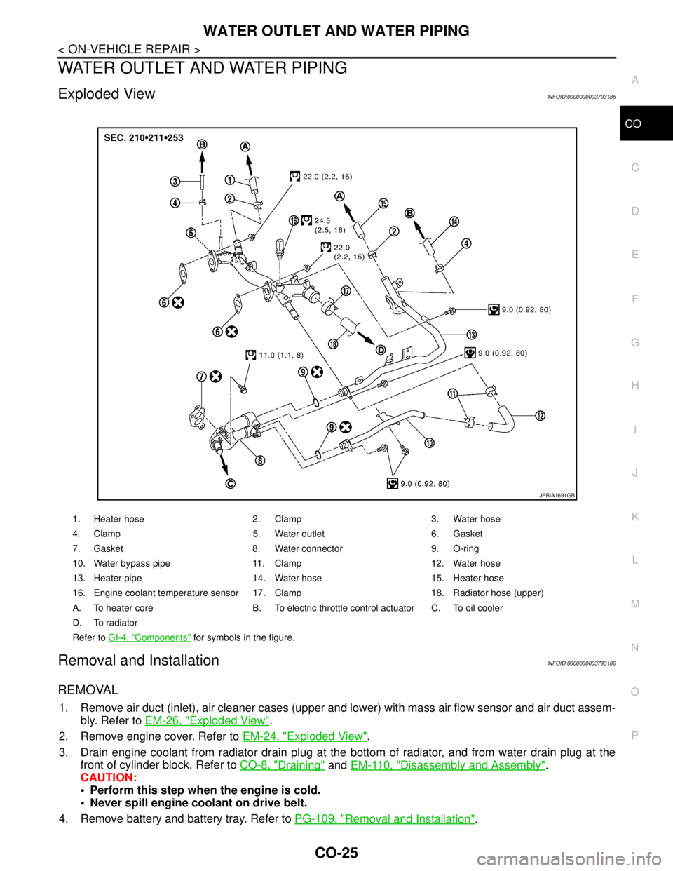
Exploded ViewINFOID:0000000003793185
Removal and InstallationINFOID:0000000003793186
REMOVAL
1. Remove air duct (inlet), air cleaner cases (upper and lower) with mass air flow sensor and air duct assem-
bly. Refer to EM-26, "
Exploded View".
2. Remove engine cover. Refer to EM-24, "
Exploded View".
3. Drain engine coolant from radiator drain plug at the bottom of radiator, and from water drain plug at the
front of cylinder block. Refer to CO-8, "
Draining" and EM-110, "Disassembly and Assembly".
CAUTION:
Perform this step when the engine is cold.
Never spill engine coolant on drive belt.
4. Remove battery and battery tray. Refer to PG-109, "
Removal and Installation".
1. Heater hose 2. Clamp 3. Water hose
4. Clamp 5. Water outlet 6. Gasket
7. Gasket 8. Water connector 9. O-ring
10. Water bypass pipe 11. Clamp 12. Water hose
13. Heater pipe 14. Water hose 15. Heater hose
16. Engine coolant temperature sensor 17. Clamp 18. Radiator hose (upper)
A. To heater core B. To electric throttle control actuator C. To oil cooler
D. To radiator
Refer to GI-4, "
Components" for symbols in the figure.
JPBIA1691GB
Page 1905 of 5121
EM-30
< ON-VEHICLE REPAIR >
INTAKE MANIFOLD COLLECTOR
2. Remove air cleaner cases (upper and lower) with mass air flow sensor and air duct assembly. Refer to
EM-26, "
Exploded View".
3. Drain engine coolant, or when water hoses are disconnected, attach plug to prevent engine coolant leak-
age. Refer to CO-8, "
Draining".
CAUTION:
Perform this step when the engine is cold.
4. Remove front wiper arm and extension cowl top. Refer to WW-105, "
Exploded View" and EXT-20,
"Exploded View".
5. Disconnect water hoses from electric throttle control actuator.
When engine coolant is not drained from radiator, attach plug to water hoses to prevent engine coolant
leakage.
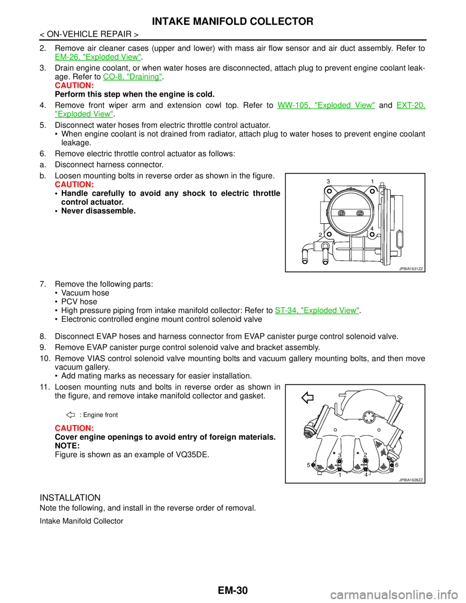
6. Remove electric throttle control actuator as follows:
a. Disconnect harness connector.
b. Loosen mounting bolts in reverse order as shown in the figure.
CAUTION:
Handle carefully to avoid any shock to electric throttle
control actuator.
Never disassemble.
7. Remove the following parts:
Vacuum hose
PCV hose
High pressure piping from intake manifold collector: Refer to ST-34, "
Exploded View".
Electronic controlled engine mount control solenoid valve
8. Disconnect EVAP hoses and harness connector from EVAP canister purge control solenoid valve.
9. Remove EVAP canister purge control solenoid valve and bracket assembly.
10. Remove VIAS control solenoid valve mounting bolts and vacuum gallery mounting bolts, and then move
vacuum gallery.
Add mating marks as necessary for easier installation.
11. Loosen mounting nuts and bolts in reverse order as shown in
the figure, and remove intake manifold collector and gasket.
CAUTION:
Cover engine openings to avoid entry of foreign materials.
NOTE:
Figure is shown as an example of VQ35DE.
INSTALLATION
Note the following, and install in the reverse order of removal.
Intake Manifold Collector
JPBIA1631ZZ
: Engine front
JPBIA1628ZZ