wheel bolts NISSAN TEANA 2008 Service Manual
[x] Cancel search | Manufacturer: NISSAN, Model Year: 2008, Model line: TEANA, Model: NISSAN TEANA 2008Pages: 5121, PDF Size: 69.03 MB
Page 932 of 5121
BR-36
< ON-VEHICLE REPAIR >
FRONT DISC BRAKE
CAUTION:
Never depress the brake pedal. Brake fluid may splash while removing the brake hose.
1. Remove tires.
2. Fix the disc rotor using wheel nuts.
3. Drain brake fluid. Refer to BR-9, "
Draining".
CAUTION:
Never spill or splash brake fluid on the disc rotor.
4. Remove union bolt and copper washers, and then disconnect brake hose from caliper assembly. Refer to
BR-19, "
FRONT : Exploded View".
5. Remove torque member mounting bolts, and remove brake caliper assembly.
CAUTION:
Never drop brake pads and caliper assembly.
6. Remove disc rotor.
CAUTION:
Put matching marks on the wheel hub and bearing assembly and the disc rotor before removing
the disc rotor.
Never drop disc rotor.
INSTALLATION
WARNING:
Clean any dust from the brake caliper and brake pads with a vacuum dust collector. Never blow with
compressed air.
CAUTION:
Never depress the brake pedal. Brake fluid may splash while removing the brake hose.
1. Install disc rotor.
CAUTION:
Align the matching marks put during removal when reusing the disc rotor.
2. Install the brake caliper assembly to the vehicle and tighten the torque member mounting bolts to the
specified torque.
CAUTION:
Never spill or splash any grease and moisture on the brake caliper assembly mounting face,
threads, mounting bolts and washers. Wipe out any grease and moisture.
3. Install brake hose and copper washers to brake caliper assembly, and tighten union bolts to the specified
torque. Refer to BR-19, "
FRONT : Exploded View".
CAUTION:
Never reuse copper washer.
4. Refill with new brake fluid and perform the air bleeding. Refer to BR-10, "
Bleeding Brake System".
CAUTION:
Never reuse drained brake fluid.
Never spill or splash brake fluid on the disc rotor.
5. Check a drag of front disc brake. If any drag is found, refer to BR-38, "
BRAKE CALIPER ASSEMBLY :
Inspection".
BRAKE CALIPER ASSEMBLY : Disassembly and AssemblyINFOID:0000000003811209
DISASSEMBLY
NOTE:
Never remove the torque member and pad retainers when disassembling and assembling the cylinder body.
1. Remove the sliding pin bolts, and remove the cylinder body from the torque member.
CAUTION:
Never drop brake pads, shims, shim cover and pad retainers from torque member.
2. Remove brake pads, shims and shim cover. Refer to BR-33, "
BRAKE PAD : Exploded View".
3. Remove sliding pins and sliding pin boots from torque member.
4. Remove bushing from sliding pin.
Page 938 of 5121
BR-42
< ON-VEHICLE REPAIR >
REAR DISC BRAKE
Clean any dust from the brake caliper and brake pads with a vacuum dust collector. Never blow with
compressed air.
CAUTION:
Never depress the brake pedal. Brake fluid may splash while removing the brake hose.
1. Remove tires.
2. Fix the disc rotor using wheel nuts.
3. Drain brake fluid. Refer to BR-9, "
Draining".
CAUTION:
Never spill or splash brake fluid on the disc rotor.
4. Remove union bolt and copper washers then disconnect brake hose from caliper assembly.
5. Remove torque member mounting bolts, and remove brake caliper assembly.
CAUTION:
Never drop brake pads and caliper assembly.
6. Remove disc rotor.
CAUTION:
Put matching marks on the wheel hub and bearing assembly and the disc rotor before removing
the disc rotor.
Never drop disc rotor.
INSTALLATION
WARNING:
Clean any dust from the brake caliper and brake pads with a vacuum dust collector. Never blow with
compressed air.
CAUTION:
Never depress the brake pedal. Brake fluid may splash while removing the brake hose.
1. Install disc rotor.
CAUTION:
Align the matching marks put during removal when reusing the disc rotor.
2. Install the brake caliper assembly to the vehicle and tighten the torque member mounting bolts to the
specified torque.
CAUTION:
Never spill or splash any grease and moisture on the brake caliper assembly mounting face,
threads, mounting bolts, and washers. Wipe out any grease and moisture.
3. Install brake hose and copper washers to brake caliper assembly, and tighten union bolts to the specified
torque. Refer to BR-22, "
REAR : Exploded View".
CAUTION:
Never reuse copper washer.
4. Refill with new brake fluid and perform the air bleeding. Refer to BR-10, "
Bleeding Brake System".
CAUTION:
Never reuse drained brake fluid.
Never spill or splash brake fluid on the disc rotor.
5. Check that no drag feel is present for the rear disc brake. Refer to BR-44, "
BRAKE CALIPER ASSEMBLY
: Inspection".
BRAKE CALIPER ASSEMBLY : Disassembly and AssemblyINFOID:0000000003811216
DISASSEMBLY
NOTE:
Never remove the torque member and pad retainers when disassembling and assembling the cylinder body.
1. Remove the sliding pin bolts and remove the cylinder body from the torque member.
2. Remove brake pads and shims. Refer to BR-39, "
BRAKE PAD : Exploded View".
3. Remove sliding pin boots from torque member.
4. Remove bushing from sliding pin bolt.
Page 998 of 5121
![NISSAN TEANA 2008 Service Manual WHEEL SENSOR
BRC-57
< ON-VEHICLE REPAIR >[ABS]
C
D
E
G
H
I
J
K
L
MA
B
BRC
N
O
P
ON-VEHICLE REPAIR
WHEEL SENSOR
FRONT WHEEL SENSOR
FRONT WHEEL SENSOR : Exploded ViewINFOID:0000000003766865
NOTE:
The ab NISSAN TEANA 2008 Service Manual WHEEL SENSOR
BRC-57
< ON-VEHICLE REPAIR >[ABS]
C
D
E
G
H
I
J
K
L
MA
B
BRC
N
O
P
ON-VEHICLE REPAIR
WHEEL SENSOR
FRONT WHEEL SENSOR
FRONT WHEEL SENSOR : Exploded ViewINFOID:0000000003766865
NOTE:
The ab](/img/5/57391/w960_57391-997.png)
WHEEL SENSOR
BRC-57
< ON-VEHICLE REPAIR >[ABS]
C
D
E
G
H
I
J
K
L
MA
B
BRC
N
O
P
ON-VEHICLE REPAIR
WHEEL SENSOR
FRONT WHEEL SENSOR
FRONT WHEEL SENSOR : Exploded ViewINFOID:0000000003766865
NOTE:
The above figure shows left side. Right side is the mirror image.
FRONT WHEEL SENSOR : Removal and InstallationINFOID:0000000003766866
REMOVAL
Be careful with the following when removing sensor.
CAUTION:
Do not twist sensor harness as much as possible, when removing it. Pull sensors out without pulling
sensor harness.
Be careful to avoid damaging sensor edges or rotor teeth. Remove wheel sensor first before remov-
ing front or rear wheel hub. This is to avoid damage to sensor wiring and loss of sensor function.
INSTALLATION
Be careful with the following when installing wheel sensor. Tighten installation bolts to the specified torques.
Refer to BRC-57, "
FRONT WHEEL SENSOR : Exploded View".
CAUTION:
When installing, make sure there is no foreign material such as iron chips on and in the mounting
hole of the wheel sensor. Make sure no foreign material has been caught in the sensor rotor. Remove
any foreign material and clean the mount.
1. Front LH wheel sensor 2. Front LH wheel sensor connector
: Vehicle front
Refer to GI section GI-4, "
Components" for symbol marks in the figure.
JSFIA0221GB
Page 999 of 5121
![NISSAN TEANA 2008 Service Manual BRC-58
< ON-VEHICLE REPAIR >[ABS]
WHEEL SENSOR
Completely push in rubber grommets of strut bracket and body bracket until they lock when install-
ing wheel sensor so that the wheel sensor harness wi NISSAN TEANA 2008 Service Manual BRC-58
< ON-VEHICLE REPAIR >[ABS]
WHEEL SENSOR
Completely push in rubber grommets of strut bracket and body bracket until they lock when install-
ing wheel sensor so that the wheel sensor harness wi](/img/5/57391/w960_57391-998.png)
BRC-58
< ON-VEHICLE REPAIR >[ABS]
WHEEL SENSOR
Completely push in rubber grommets of strut bracket and body bracket until they lock when install-
ing wheel sensor so that the wheel sensor harness will not be twisted. Install grommet groove onto
bracket with orange line on the harness facing bracket opening (mounting hole). There should be no
twists in the harness when installed.
REAR WHEEL SENSOR
REAR WHEEL SENSOR : Exploded ViewINFOID:0000000003766867
NOTE:
The above figure shows left side. Right side is the mirror image.
REAR WHEEL SENSOR : Removal and InstallationINFOID:0000000003766868
REMOVAL
Be careful with the following when removing sensor.
CAUTION:
Do not twist sensor harness as much as possible, when removing it. Pull sensors out without pulling
sensor harness.
Be careful to avoid damaging sensor edges or rotor teeth. Remove wheel sensor first before remov-
ing front or rear wheel hub. This is to avoid damage to sensor wiring and loss of sensor function.
INSTALLATION
Be careful with the following when installing wheel sensor. Tighten installation bolts to the specified torques.
Refer to BRC-58, "
REAR WHEEL SENSOR : Exploded View".
CAUTION:
When installing, make sure there is no foreign material such as iron chips on and in the mounting hole
of the wheel sensor. Make sure no foreign material has been caught in the sensor rotor. Remove any
foreign material and clean the mount.
1. Rear LH wheel sensor connector 2. Rear LH wheel sensor
: Vehicle front
Refer to GI section GI-4, "
Components" for symbol marks in the figure.
JSFIA0222GB
Page 1092 of 5121
![NISSAN TEANA 2008 Service Manual WHEEL SENSOR
BRC-151
< ON-VEHICLE REPAIR >[VDC/TCS/ABS]
C
D
E
G
H
I
J
K
L
MA
B
BRC
N
O
P
ON-VEHICLE REPAIR
WHEEL SENSOR
FRONT WHEEL SENSOR
FRONT WHEEL SENSOR : Exploded ViewINFOID:0000000003767300
NOT NISSAN TEANA 2008 Service Manual WHEEL SENSOR
BRC-151
< ON-VEHICLE REPAIR >[VDC/TCS/ABS]
C
D
E
G
H
I
J
K
L
MA
B
BRC
N
O
P
ON-VEHICLE REPAIR
WHEEL SENSOR
FRONT WHEEL SENSOR
FRONT WHEEL SENSOR : Exploded ViewINFOID:0000000003767300
NOT](/img/5/57391/w960_57391-1091.png)
WHEEL SENSOR
BRC-151
< ON-VEHICLE REPAIR >[VDC/TCS/ABS]
C
D
E
G
H
I
J
K
L
MA
B
BRC
N
O
P
ON-VEHICLE REPAIR
WHEEL SENSOR
FRONT WHEEL SENSOR
FRONT WHEEL SENSOR : Exploded ViewINFOID:0000000003767300
NOTE:
The above figure shows left side. Right side is the mirror image.
FRONT WHEEL SENSOR : Removal and InstallationINFOID:0000000003767301
REMOVAL
Be careful with the following when removing sensor.
CAUTION:
Do not twist sensor harness as much as possible, when removing it. Pull sensors out without pulling
sensor harness.
Be careful to avoid damaging sensor edges or rotor teeth. Remove wheel sensor first before remov-
ing front or rear wheel hub. This is to avoid damage to sensor wiring and loss of sensor function.
INSTALLATION
Be careful with the following when installing wheel sensor. Tighten installation bolts to the specified torques.
Refer to BRC-151, "
FRONT WHEEL SENSOR : Exploded View".
CAUTION:
When installing, make sure there is no foreign material such as iron chips on and in the mounting
hole of the wheel sensor. Make sure no foreign material has been caught in the sensor rotor. Remove
any foreign material and clean the mount.
1. Front LH wheel sensor 2. Front LH wheel sensor connector
: Vehicle front
Refer to GI section GI-4, "
Components" for symbol marks in the figure.
JSFIA0221GB
Page 1093 of 5121
![NISSAN TEANA 2008 Service Manual BRC-152
< ON-VEHICLE REPAIR >[VDC/TCS/ABS]
WHEEL SENSOR
Completely push in rubber grommets of strut bracket and body bracket until they lock when install-
ing wheel sensor so that the wheel sensor h NISSAN TEANA 2008 Service Manual BRC-152
< ON-VEHICLE REPAIR >[VDC/TCS/ABS]
WHEEL SENSOR
Completely push in rubber grommets of strut bracket and body bracket until they lock when install-
ing wheel sensor so that the wheel sensor h](/img/5/57391/w960_57391-1092.png)
BRC-152
< ON-VEHICLE REPAIR >[VDC/TCS/ABS]
WHEEL SENSOR
Completely push in rubber grommets of strut bracket and body bracket until they lock when install-
ing wheel sensor so that the wheel sensor harness will not be twisted. Install grommet groove onto
bracket with orange line on the harness facing bracket opening (mounting hole). There should be no
twists in the harness when installed.
REAR WHEEL SENSOR
REAR WHEEL SENSOR : Exploded ViewINFOID:0000000003767302
NOTE:
The above figure shows left side. Right side is the mirror image.
REAR WHEEL SENSOR : Removal and InstallationINFOID:0000000003767303
REMOVAL
Be careful with the following when removing sensor.
CAUTION:
Do not twist sensor harness as much as possible, when removing it. Pull sensors out without pulling
sensor harness.
Be careful to avoid damaging sensor edges or rotor teeth. Remove wheel sensor first before remov-
ing front or rear wheel hub. This is to avoid damage to sensor wiring and loss of sensor function.
INSTALLATION
Be careful with the following when installing wheel sensor. Tighten installation bolts to the specified torques.
Refer to BRC-152, "
REAR WHEEL SENSOR : Exploded View".
CAUTION:
When installing, make sure there is no foreign material such as iron chips on and in the mounting hole
of the wheel sensor. Make sure no foreign material has been caught in the sensor rotor. Remove any
foreign material and clean the mount.
1. Rear LH wheel sensor connector 2. Rear LH wheel sensor
: Vehicle front
Refer to GI section GI-4, "
Components" for symbol marks in the figure.
JSFIA0222GB
Page 1881 of 5121

EM-6
< PRECAUTION >
PRECAUTIONS
3. Disconnect both battery cables. The steering lock will remain released with both battery cables discon-
nected and the steering wheel can be turned.
4. Perform the necessary repair operation.
5. When the repair work is completed, re-connect both battery cables. With the brake pedal released, turn
the push-button ignition switch from ACC position to ON position, then to LOCK position. (The steering
wheel will lock when the push-button ignition switch is turned to LOCK position.)
6. Perform self-diagnosis check of all control units using CONSULT-III.
Precaution for Drain Engine Coolant and Engine OilINFOID:0000000003802227
Drain engine coolant and engine oil when the engine is cooled.
Precaution for Disconnecting Fuel PipingINFOID:0000000003802228
Before starting work, check no fire or spark producing items are in the work area.
Release fuel pressure before disconnecting and disassembly.
After disconnecting pipes, plug openings to stop fuel leakage.
Precaution for Removal and DisassemblyINFOID:0000000003802229
When instructed to use SST, use the specified tools. Always be careful to work safely, avoid forceful or unin-
structed operations.
Exercise maximum care to avoid damage to mating or sliding surfaces.
Dowel pins are used for several parts alignment. When replacing and reassembling parts with dowel pins,
check that dowel pins are installed in the original position.
Cover openings of engine system with a tape or the equivalent, if necessary, to seal out foreign materials.
Mark and arrange disassembly parts in an organized way for easy troubleshooting and reassembly.
When loosening nuts and bolts, as a basic rule, start with the one furthest outside, then the one diagonally
opposite, and so on. If the order of loosening is specified, do exactly as specified. Power tools may be used
in the step.
Precaution for Inspection, Repair and ReplacementINFOID:0000000003802230
Before repairing or replacing, thoroughly inspect parts. Inspect new replacement parts in the same way, and
replace if necessary.
Precaution for Assembly and InstallationINFOID:0000000003802231
Use torque wrench to tighten bolts or nuts to specification.
When tightening nuts and bolts, as a basic rule, equally tighten in several different steps starting with the
ones in center, then ones on inside and outside diagonally in this order. If the order of tightening is specified,
do exactly as specified.
Replace with new gasket, packing, oil seal or O-ring.
Dowel pins are used for several parts alignment. When replacing and reassembling parts with dowel pins,
check that dowel pins are installed in the original position.
Thoroughly wash, clean, and air-blow each part. Carefully check engine oil or engine coolant passages for
any restriction and blockage.
Avoid damaging sliding or mating surfaces. Completely remove foreign materials such as cloth lint or dust.
Before assembly, oil sliding surfaces well.
Release air within route when refilling after draining engine coolant.
After repairing, start the engine and increase engine speed to check engine coolant, fuel, engine oil, and
exhaust gases for leakage.
Precaution for Angle TighteningINFOID:0000000003802232
Use the angle wrench [SST: KV10112100 (BT8653-A)] for the final tightening of the following engine parts:
- Cylinder head bolts
- Main bearing cap bolts
- Connecting rod cap bolts
- Crankshaft pulley bolt (No the angle wrench is required as bolt flange is provided with notches for angle
tightening)
Never use a torque value for final tightening.
The torque value for these parts are for a preliminary step.
Page 1943 of 5121
EM-68
< REMOVAL AND INSTALLATION >
ENGINE ASSEMBLY
Place chocks at front and back of rear wheels.
For engines not equipped with engine slingers, attach proper slingers and bolts described in PARTS
CATALOG.
CAUTION:
Always be careful to work safely, avoid forceful or uninstructed operations.
Never start working until exhaust system and engine coolant are cool enough.
If items or work required are not covered by the engine section, refer to the applicable sections.
Always use the support point specified for lifting.
Use either 2-pole lift type or separate type lift as best you can. If board-on type is used for unavoid-
able reasons, support at the rear axle jacking point with transmission jack or similar tool before
starting work, in preparation for the backward shift of center of gravity.
For supporting points for lifting and jacking point at rear axle, refer to GI-30, "
Garage Jack and
Safety Stand and 2-Pole Lift".
REMOVAL
Outline
At first, remove the engine and the transaxle assembly with front suspension member downward. Then sepa-
rate the engine and the transaxle.
Preparation
1. Release fuel pressure. Refer to EC-411, "Inspection".
2. Drain engine coolant. Refer to CO-8, "
Draining".
CAUTION:
Perform this step when the engine is cold.
Never spill engine coolant on drive belt.
3. Remove the following parts:
Engine cover: Refer to EM-24, "
Exploded View".
Front road wheel and tires
Splash guards (RH and LH): Refer to EXT-22, "
FENDER PROTECTOR : Exploded View".
Air duct (inlet), air cleaner cases (upper and lower) with mass air flow sensor and air duct assembly:
Refer to EM-26, "
Exploded View".
Battery and battery tray: Refer to PG-109, "
Removal and Installation".
Drive belt: Refer to EM-12, "
Removal and Installation".
Reservoir tank of radiator. Refer to CO-13, "
Exploded View".
Front wiper arm: Refer to WW-105, "
Exploded View".
4. Disconnect engine room harness at the TCM, ECM and other sides.
CAUTION:
To keep clean harness connector and avoid damage and foreign materials, cover them completely
with plastic bags or something similar.
5. Remove battery bracket with ECM and TCM.
6. Remove extension cowl top. Refer to EXT-20, "
Exploded View".
Engine Room
1. Disconnect heater hoses. Refer to CO-25, "Exploded View".
Install plug to avoid leakage of engine coolant.
2. Remove EVAP hose. Refer to EM-28, "
Exploded View".
3. Disconnect fuel feed hose quick connector at fuel tube side. Refer to EM-44, "
Exploded View".
Install plug to avoid leakage of fuel.
4. Disconnect transaxle shift control cable at transaxle side. Refer to TM-319, "
Exploded View" (VQ25DE) or
TM-157, "
Exploded View" (VQ35DE).
5. Disconnect brake booster vacuum hose at engine side. Refer to EM-28, "
Exploded View".
6. Disconnect ground cable.
7. Disconnect A/C compressor piping at A/C compressor side. Refer to HA-36, "
Exploded View".
8. Disconnect suction hoses of power steering oil pump at reservoir tank side. Refer to ST-34, "
Exploded
View".
Install plug to avoid leakage of power steering fluid.
9. Disconnect CVT fluid cooler hoses from radiator. Refer to CO-13, "
Exploded View".
Page 1944 of 5121
ENGINE ASSEMBLY
EM-69
< REMOVAL AND INSTALLATION >
C
D
E
F
G
H
I
J
K
L
MA
EM
N
P O
10. Remove starter motor. Refer to STR-15, "VQ25DE : Exploded View" (VQ25DE) or STR-20, "VQ35DE :
Exploded View" (VQ35DE).
Vehicle Underbody
1. Remove front drive shafts (RH and LH). Refer to FAX-16, "Exploded View".
2. Remove exhaust front tube. Refer to EX-5, "
Exploded View".
3. Remove heat insulator.
4. Disconnect steering lower joint at power steering gear assembly side, and release steering lower shaft.
Refer to ST-16, "
Exploded View".
5. Disconnect front stabilizer connecting rod. Refer to FSU-14, "
Exploded View".
6. Remove strut assembly and steering knuckle fixing nuts and bolts. Refer to FSU-9, "
Exploded View" and
FA X - 8 , "
Exploded View".
7. Remove front wheel sensor (RH and LH) for ABS from steering knuckle. Refer to BRC-57, "
FRONT
WHEEL SENSOR : Exploded View".
8. Remove front brake caliper assembly with piping connected, and temporarily secure it to aside for vehicle
side. Refer to BR-34, "
BRAKE CALIPER ASSEMBLY : Exploded View".
9. Disconnect power steering piping at a point between vehicle and engine. Refer to ST-34, "
Exploded
View".
Install plug to avoid leakage of power steering fluid.
10. Remove rear plate cover from oil pan (upper). Then remove bolts fixing drive plate to torque converter.
Refer to EM-38, "
Exploded View" and TM-332, "Removal and Installation" (VQ25DE) or TM-168,
"Removal and Installation" (VQ35DE).
11. Remove transaxle joint bolts which pierce at oil pan (upper) lower rear side. Refer to EM-38, "
Exploded
View".
12. Remove crankshaft position sensor (POS). Refer to EM-38, "
Exploded View".
CAUTION:
Handle carefully to avoid dropping and shocks.
Never disassemble.
Never allow metal powder to adhere to magnetic part at sensor tip.
Never place sensors in a location where they are exposed to magnetism.
Removal
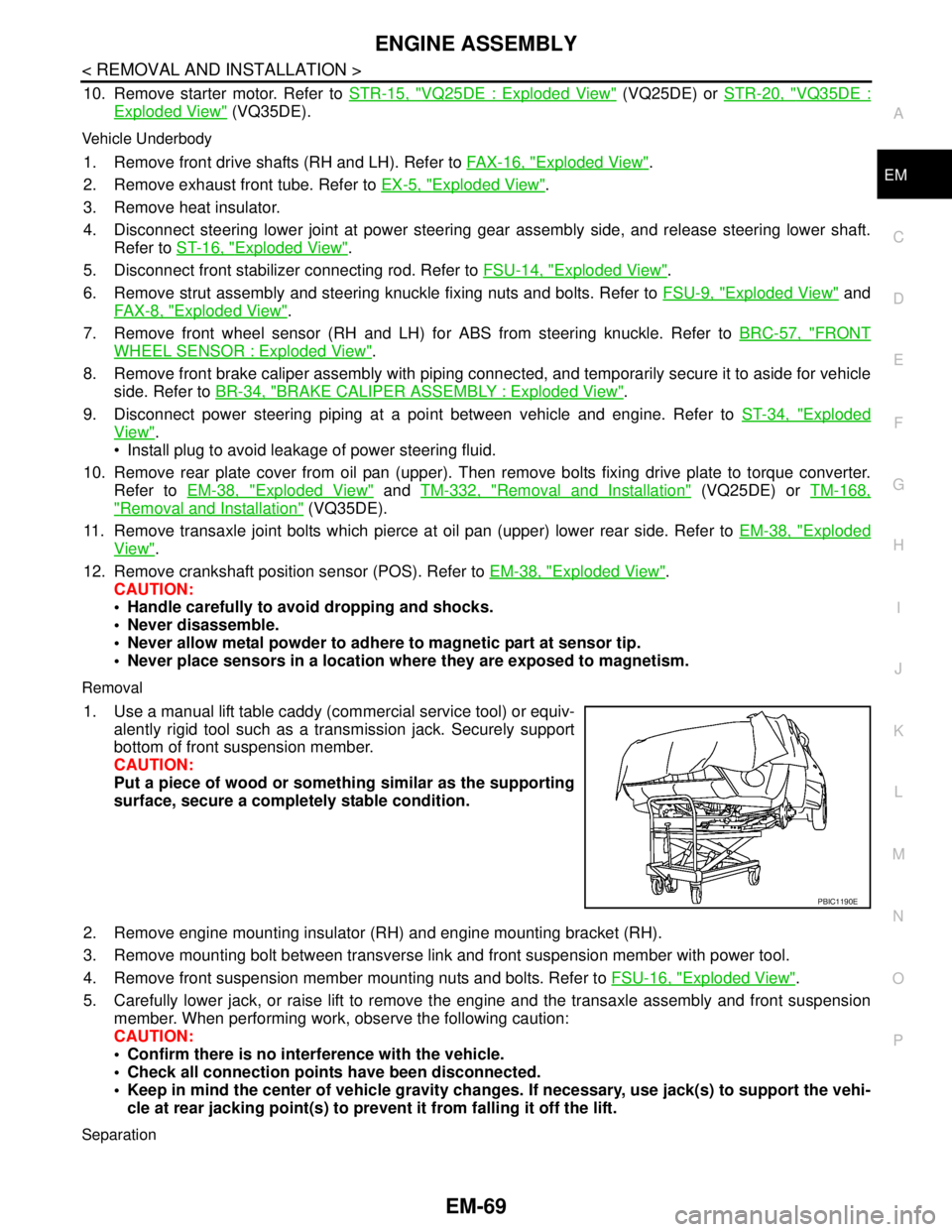
1. Use a manual lift table caddy (commercial service tool) or equiv-
alently rigid tool such as a transmission jack. Securely support
bottom of front suspension member.
CAUTION:
Put a piece of wood or something similar as the supporting
surface, secure a completely stable condition.
2. Remove engine mounting insulator (RH) and engine mounting bracket (RH).
3. Remove mounting bolt between transverse link and front suspension member with power tool.
4. Remove front suspension member mounting nuts and bolts. Refer to FSU-16, "
Exploded View".
5. Carefully lower jack, or raise lift to remove the engine and the transaxle assembly and front suspension
member. When performing work, observe the following caution:
CAUTION:
Confirm there is no interference with the vehicle.
Check all connection points have been disconnected.
Keep in mind the center of vehicle gravity changes. If necessary, use jack(s) to support the vehi-
cle at rear jacking point(s) to prevent it from falling it off the lift.
Separation
PBIC1190E
Page 2447 of 5121
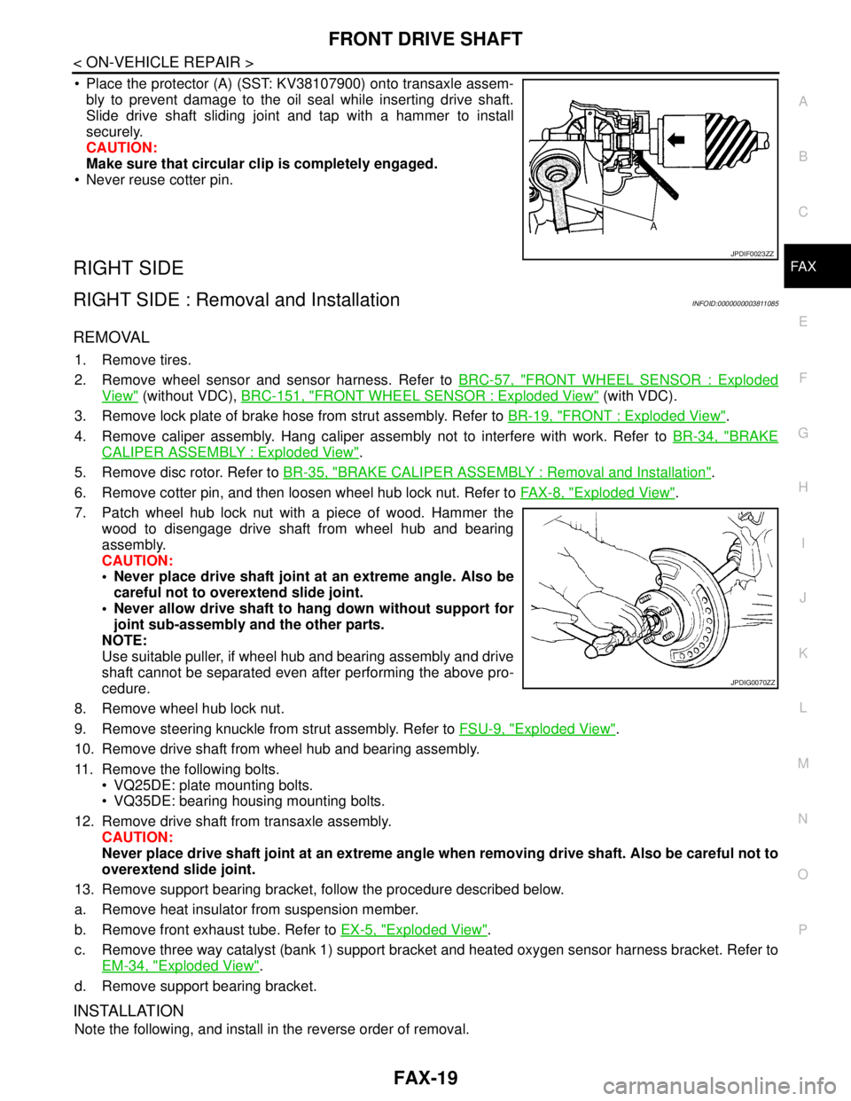
FRONT DRIVE SHAFT
FAX-19
< ON-VEHICLE REPAIR >
C
E
F
G
H
I
J
K
L
MA
B
FA X
N
O
P
Place the protector (A) (SST: KV38107900) onto transaxle assem-
bly to prevent damage to the oil seal while inserting drive shaft.
Slide drive shaft sliding joint and tap with a hammer to install
securely.
CAUTION:
Make sure that circular clip is completely engaged.
Never reuse cotter pin.
RIGHT SIDE
RIGHT SIDE : Removal and InstallationINFOID:0000000003811085
REMOVAL
1. Remove tires.
2. Remove wheel sensor and sensor harness. Refer to BRC-57, "
FRONT WHEEL SENSOR : Exploded
View" (without VDC), BRC-151, "FRONT WHEEL SENSOR : Exploded View" (with VDC).
3. Remove lock plate of brake hose from strut assembly. Refer to BR-19, "
FRONT : Exploded View".
4. Remove caliper assembly. Hang caliper assembly not to interfere with work. Refer to BR-34, "
BRAKE
CALIPER ASSEMBLY : Exploded View".
5. Remove disc rotor. Refer to BR-35, "
BRAKE CALIPER ASSEMBLY : Removal and Installation".
6. Remove cotter pin, and then loosen wheel hub lock nut. Refer to FA X - 8 , "
Exploded View".
7. Patch wheel hub lock nut with a piece of wood. Hammer the
wood to disengage drive shaft from wheel hub and bearing
assembly.
CAUTION:
Never place drive shaft joint at an extreme angle. Also be
careful not to overextend slide joint.
Never allow drive shaft to hang down without support for
joint sub-assembly and the other parts.
NOTE:
Use suitable puller, if wheel hub and bearing assembly and drive
shaft cannot be separated even after performing the above pro-
cedure.
8. Remove wheel hub lock nut.
9. Remove steering knuckle from strut assembly. Refer to FSU-9, "
Exploded View".
10. Remove drive shaft from wheel hub and bearing assembly.
11. Remove the following bolts.
VQ25DE: plate mounting bolts.
VQ35DE: bearing housing mounting bolts.
12. Remove drive shaft from transaxle assembly.
CAUTION:
Never place drive shaft joint at an extreme angle when removing drive shaft. Also be careful not to
overextend slide joint.
13. Remove support bearing bracket, follow the procedure described below.
a. Remove heat insulator from suspension member.
b. Remove front exhaust tube. Refer to EX-5, "
Exploded View".
c. Remove three way catalyst (bank 1) support bracket and heated oxygen sensor harness bracket. Refer to
EM-34, "
Exploded View".
d. Remove support bearing bracket.
INSTALLATION
Note the following, and install in the reverse order of removal.
JPDIF0023ZZ
JPDIG0070ZZ