low NISSAN TEANA 2008 Service Manual
[x] Cancel search | Manufacturer: NISSAN, Model Year: 2008, Model line: TEANA, Model: NISSAN TEANA 2008Pages: 5121, PDF Size: 69.03 MB
Page 4 of 5121

ACC-2
< PRECAUTION >
PRECAUTIONS
PRECAUTION
PRECAUTIONS
Precaution for Supplemental Restraint System (SRS) "AIR BAG" and "SEAT BELT
PRE-TENSIONER"
INFOID:0000000003801897
The Supplemental Restraint System such as “AIR BAG” and “SEAT BELT PRE-TENSIONER”, used along
with a front seat belt, helps to reduce the risk or severity of injury to the driver and front passenger for certain
types of collision. This system includes seat belt switch inputs and dual stage front air bag modules. The SRS
system uses the seat belt switches to determine the front air bag deployment, and may only deploy one front
air bag, depending on the severity of a collision and whether the front occupants are belted or unbelted.
Information necessary to service the system safely is included in the “SRS AIRBAG” and “SEAT BELT” of this
Service Manual.
WARNING:
• To avoid rendering the SRS inoperative, which could increase the risk of personal injury or death in
the event of a collision which would result in air bag inflation, all maintenance must be performed by
an authorized NISSAN/INFINITI dealer.
Improper maintenance, including incorrect removal and installation of the SRS, can lead to personal
injury caused by unintentional activation of the system. For removal of Spiral Cable and Air Bag
Module, see the “SRS AIRBAG”.
Do not use electrical test equipment on any circuit related to the SRS unless instructed to in this
Service Manual. SRS wiring harnesses can be identified by yellow and/or orange harnesses or har-
ness connectors.
Page 5 of 5121
ACCELERATOR CONTROL SYSTEM
ACC-3
< ON-VEHICLE REPAIR >
C
D
E
F
G
H
I
J
K
L
MA
ACC
N
P O
ON-VEHICLE REPAIR
ACCELERATOR CONTROL SYSTEM
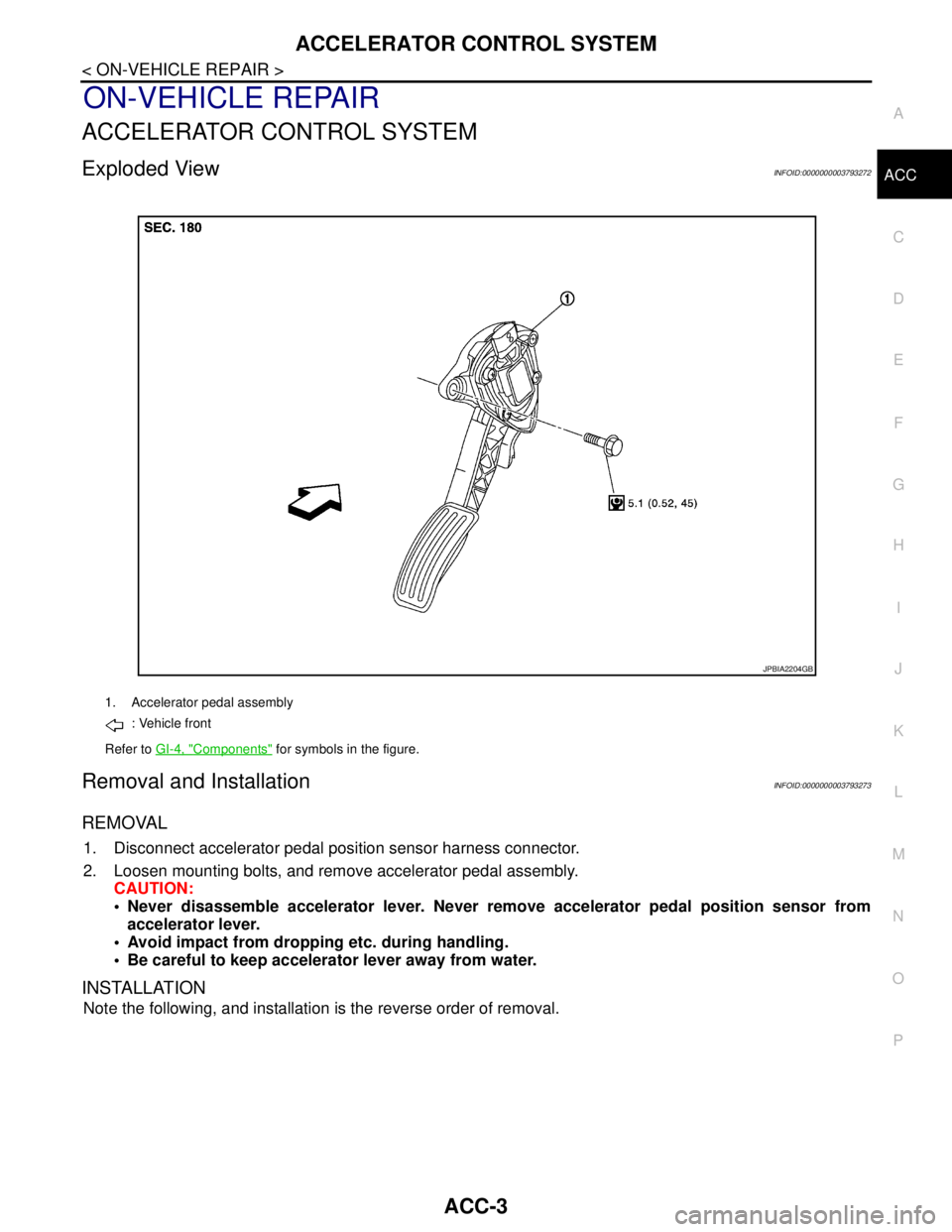
Exploded ViewINFOID:0000000003793272
Removal and InstallationINFOID:0000000003793273
REMOVAL
1. Disconnect accelerator pedal position sensor harness connector.
2. Loosen mounting bolts, and remove accelerator pedal assembly.
CAUTION:
Never disassemble accelerator lever. Never remove accelerator pedal position sensor from
accelerator lever.
Avoid impact from dropping etc. during handling.
Be careful to keep accelerator lever away from water.
INSTALLATION
Note the following, and installation is the reverse order of removal.
1. Accelerator pedal assembly
: Vehicle front
Refer to GI-4, "
Components" for symbols in the figure.
JPBIA2204GB
Page 7 of 5121

ADP-1
BODY INTERIOR
C
D
E
F
G
H
I
K
L
M
SECTION ADP
A
B
ADP
N
O
P
CONTENTS
AUTOMATIC DRIVE POSITIONER
BASIC INSPECTION ....................................4
DIAGNOSIS AND REPAIR WORKFLOW ..........4
Work Flow .................................................................4
INSPECTION AND ADJUSTMENT .....................7
ADDITIONAL SERVICE WHEN REMOVING BAT-
TERY NEGATIVE TERMINAL .....................................
7
ADDITIONAL SERVICE WHEN REMOVING
BATTERY NEGATIVE TERMINAL : Description ......
7
ADDITIONAL SERVICE WHEN REMOVING
BATTERY NEGATIVE TERMINAL : Special Re-
pair Requirement .......................................................
7
ADDITIONAL SERVICE WHEN REPLACING
CONTROL UNIT ..........................................................
7
ADDITIONAL SERVICE WHEN REPLACING
CONTROL UNIT : Description ..................................
7
ADDITIONAL SERVICE WHEN REPLACING
CONTROL UNIT : Special Repair Requirement .......
7
SYSTEM INITIALIZATION ..........................................8
SYSTEM INITIALIZATION : Description ...................8
SYSTEM INITIALIZATION : Special Repair Re-
quirement ..................................................................
8
MEMORY STORING ....................................................8
MEMORY STORING : Description ............................8
MEMORY STORING : Special Repair Require-
ment ..........................................................................
9
SYSTEM SETTING ......................................................9
SYSTEM SETTING : Description ..............................9
SYSTEM SETTING : Special Repair Requirement
....
10
FUNCTION DIAGNOSIS ..............................12
AUTOMATIC DRIVE POSITIONER SYSTEM ....12
AUTOMATIC DRIVE POSITIONER SYSTEM ...........12
AUTOMATIC DRIVE POSITIONER SYSTEM :
System Diagram ......................................................
12
AUTOMATIC DRIVE POSITIONER SYSTEM :
System Description ..................................................
12
AUTOMATIC DRIVE POSITIONER SYSTEM :
Component Parts Location ......................................
14
AUTOMATIC DRIVE POSITIONER SYSTEM :
Component Description ..........................................
15
MANUAL FUNCTION ................................................16
MANUAL FUNCTION : System Diagram ................16
MANUAL FUNCTION : System Description ............16
MANUAL FUNCTION : Component Parts Loca-
tion ...........................................................................
17
MANUAL FUNCTION : Component Description .....18
MEMORY FUNCTION ................................................18
MEMORY FUNCTION : System Diagram ...............19
MEMORY FUNCTION : System Description ...........19
MEMORY FUNCTION : Component Parts Loca-
tion ...........................................................................
21
MEMORY FUNCTION : Component Description ....22
EXIT ASSIST FUNCTION ..........................................22
EXIT ASSIST FUNCTION : System Diagram ..........23
EXIT ASSIST FUNCTION : System Description .....23
EXIT ASSIST FUNCTION : Component Parts Lo-
cation .......................................................................
25
EXIT ASSIST FUNCTION :
Component Description ..........................................
26
ENTRY ASSIST FUNCTION ......................................26
ENTRY ASSIST FUNCTION : System Diagram .....27
ENTRY ASSIST FUNCTION : System Description
....
27
ENTRY ASSIST FUNCTION : Component Parts
Location ...................................................................
29
ENTRY ASSIST FUNCTION :
Component Description ..........................................
30
INTELLIGENT KEY INTERLOCK FUNCTION ..........30
Page 10 of 5121
ADP-4
< BASIC INSPECTION >
DIAGNOSIS AND REPAIR WORKFLOW
BASIC INSPECTION
DIAGNOSIS AND REPAIR WORKFLOW
Work FlowINFOID:0000000003759057
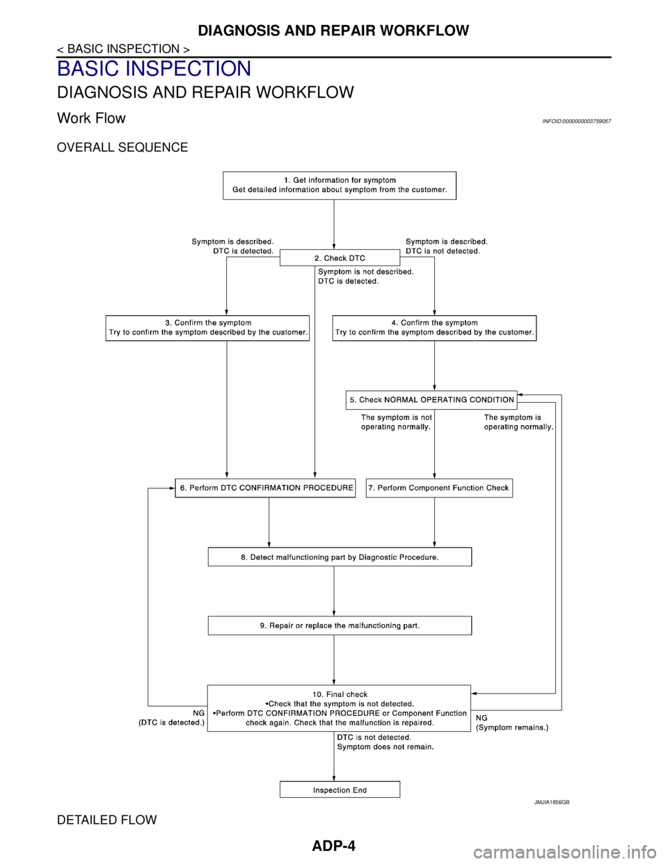
OVERALL SEQUENCE
DETAILED FLOW
JMJIA1856GB
Page 11 of 5121
DIAGNOSIS AND REPAIR WORKFLOW
ADP-5
< BASIC INSPECTION >
C
D
E
F
G
H
I
K
L
MA
B
ADP
N
O
P
1.GET INFORMATION FOR SYMPTOM
Get detailed information from the customer about the symptom (the condition and the environment when the
incident/malfunction occurs).
>> GO TO 2.
2.CHECK DTC WITH AUTOMATIC DRIVE POSITIONER SYSTEM
Check “Self Diagnostic Result” with CONSULT-III. Refer to ADP-124, "
DTCIndex"
Are any symptoms described and any DTC displayed?
Symptom is described, DTC is detected.>>GO TO 3.
Symptom is not described, DTC is detected.>>GO TO 6.
Symptom is described, DTC is not detected.>>GO TO 4.
3.CONFIRM THE SYMPTOM
Try to confirm the symptom described by the customer.
>> GO TO 6.
4.CONFIRM THE SYMPTOM
Try to confirm the symptom described by the customer.
>> GO TO 5.
5.CHECK NORMAL OPERATING CONDITION
Check normal operating condition. Refer to ADP-134, "
Description".
Is the incident a normal operation?
YES >> GO TO 10.
NO >> GO TO 7.
6.PERFORM DTC CONFIRMATION PROCEDURE
Perform the confirmation procedure for the detected DTC.
Is the DTC displayed?
YES >> GO TO 8.
NO >> Check intermittent incident. Refer to GI-35, "
Intermittent Incident".
7.PERFORM COMPONENT FUNCTION CHECK
Perform the component function check for the isolated malfunctioning point.
>> GO TO 8.
8.DETECT MALFUNCTIONING PART BY DIAGNOSTIC PROCEDURE
Isolate the malfunctioning point by performing the diagnosis procedure relevant to the symptom during the
component diagnosis.
>> GO TO 9.
9.REPARE OR REPLACE
Repair or replace the malfunctioning part.
>> GO TO 10.
10.FINAL CHECK
Perform the DTC confirmation procedure (if DTC is detected) or component function check (if no DTC is
detected) again. Check that the malfunction is repaired.
Are all malfunctions repaired?
Page 12 of 5121

ADP-6
< BASIC INSPECTION >
DIAGNOSIS AND REPAIR WORKFLOW
YES >> INSPECTION END
Symptom is detected.>> GO TO 5.
DTC is detected.>> GO TO 6.
Page 13 of 5121
INSPECTION AND ADJUSTMENT
ADP-7
< BASIC INSPECTION >
C
D
E
F
G
H
I
K
L
MA
B
ADP
N
O
P
INSPECTION AND ADJUSTMENT
ADDITIONAL SERVICE WHEN REMOVING BATTERY NEGATIVE TERMINAL
ADDITIONAL SERVICE WHEN REMOVING BATTERY NEGATIVE TERMINAL : De-
scription
INFOID:0000000003759058
Each function is reset to the following condition when the battery terminal is disconnected.
*1: Default value is 40mm.
NOTE:
Notice that disconnecting the battery when detected DTC are present will erase the DTC memory.
ADDITIONAL SERVICE WHEN REMOVING BATTERY NEGATIVE TERMINAL : Spe-
cial Repair Requirement
INFOID:0000000003759059
1.SYSTEM INITIALIZATION
Perform system initialization. Refer to ADP-8, "
SYSTEM INITIALIZATION : Description".
>> GO TO 2.
2.SYSTEM SETTING
Perform system setting. Refer to ADP-9, "
SYSTEM SETTING : Description".
>> GO TO 3.
3.MEMORY STORAGE
Perform memory storage. Refer to ADP-8, "
MEMORY STORING : Description".
>> END
ADDITIONAL SERVICE WHEN REPLACING CONTROL UNIT
ADDITIONAL SERVICE WHEN REPLACING CONTROL UNIT : Description
INFOID:0000000003759060
Each function is reset to the following condition when the driver seat control unit is replaced.
*1: Default value is 40 mm.
NOTE:
Notice that disconnecting the battery when detected DTC are present will erase the DTC memory.
ADDITIONAL SERVICE WHEN REPLACING CONTROL UNIT : Special Repair Re-
Function Condition Procedure
Memory (Seat) Erased Perform memory storage
Entry/exit assist OFFPerform system initialization
Set slide amount
*1
Intelligent Key interlock ErasedPerform system initialization
Perform memory storage
Function Condition Procedure
Memory (Seat) Erased Perform memory storage
Entry/exit assist OFFPerform system initialization
Set slide amount
*1
Intelligent Key interlock ErasedPerform system initialization
Perform memory storage
Page 15 of 5121

INSPECTION AND ADJUSTMENT
ADP-9
< BASIC INSPECTION >
C
D
E
F
G
H
I
K
L
MA
B
ADP
N
O
P
MEMORY STORING : Special Repair RequirementINFOID:0000000003759065
Memory Storage Procedure
Two positions for the driver seat can be stored for memory operation by the following procedure.
1.STEP 1
Shift selector lever to the P position.
>> GO TO 2.
2.STEP 2
Turn ignition switch ON.
>> GO TO 3.
3.STEP 3
Adjust driver seat position manually.
>> GO TO 4.
4.STEP 4
1. Push set switch.
NOTE:
Memory indicator for which driver seat position is already retained in memory is illuminated for 5 sec-
onds.
Memory indicator for which driver seat position is not retained in memory is illuminated for 0.5 seconds.
2. Push the memory switch (1 or 2) for at least 1 second within 5 seconds after pushing the set switch.
NOTE:
When entering driver seat positions into blank memory, memory indicator turns ON for 5 seconds.
When changing driver seat positions, memory indicator turns OFF for 0.5 seconds, then turns ON for 5
seconds.
NOTE:
If memory is stored in the same memory switch, the previous memory will be deleted.
Do you need to link Intelligent Keys?
YES >> GO TO 5.
NO >> END
5.STEP 6
Push the Intelligent Key unlock button within 5 seconds after pushing memory switch (while the memory indi-
cator is ON).
>> GO TO 6.
6.STEP 7
Confirm the operation of each part with memory operation and Intelligent Key interlock operation.
>> END
SYSTEM SETTING
SYSTEM SETTING : DescriptionINFOID:0000000003759066
The settings of the automatic driving positioner system can be changed, using CONSULT-III, the display unit
in the center of the instrument panel and the set switch. Always check the settings before and after discon-
necting the battery terminal or replacing driver seat control unit.
Setting Change
Page 19 of 5121

AUTOMATIC DRIVE POSITIONER SYSTEM
ADP-13
< FUNCTION DIAGNOSIS >
C
D
E
F
G
H
I
K
L
MA
B
ADP
N
O
P
The seat control unit adopts the sleep mode to reduce the electric power consumption.
The sleep mode is activated when all of the following conditions are fulfilled.
1. Ignition switch turns OFF (Steering LOCK position)
2. No load is applied to the seat control
3. The seat control unit 45 seconds timer is not activated
4. Set switch and memory switch (1 and 2) turn OFF
WAKE-UP MODE
The sleep mode is cancelled when any status change is detected for the followings.
1. CAN communication
2. Power seat switch
3. Set switch and memory switch (1 and 2)
Page 21 of 5121

AUTOMATIC DRIVE POSITIONER SYSTEM
ADP-15
< FUNCTION DIAGNOSIS >
C
D
E
F
G
H
I
K
L
MA
B
ADP
N
O
P
AUTOMATIC DRIVE POSITIONER SYSTEM : Component DescriptionINFOID:0000000003759071
CONTROL UNITS
INPUT PARTS
Switches
Sensors
OUTPUT PARTS
10. Lifting motor (rear) (driver side) B456 11. Power seat switch (driver side) B459
(sliding, lifting switch)12. Power seat switch (driver side) B459
(reclining switch)
13. TCM (transmission control module)
F2314. Control device (detention switch)
M5715. ABS actuator and electric unit (con-
trol unit) E36
A. Behind the combination meter B. View with seat cushion and seatback
pad removedC. Back side of the seat cushion
D. Engine room (LH) E. View with the center console assem-
bly removedF. Engine room (RH)
Item Function
Driver seat control unit Main unit of automatic drive positioner system
Connected to the CAN
BCMTransmits the following status to the driver seat control unit via CAN communication
Driver door: OPEN/CLOSE
Ignition switch position: ACC/ON
Door lock: UNLOCK (with Intelligent Key or driver side door request switch oper-
ation)
Key ID
Key switch: Insert/Pull out Intelligent Key
Starter: CRANKING/OTHER
Steering lock unit status: Lock/Unlock
Handle position
Combination meter / ABS actuator and
electric unit (control unit)Transmits the vehicle speed signal to the driver seat control unit via CAN commu-
nication
AV control unit The setting change of auto drive positioner system can be performed on the display
TCMTransmits the shift position signal (P range) to the driver seat control unit via CAN
communication
Item Function
Key slot The key switch is installed to detect the key inserted/removed status
Front door switch (driver side) Detects front door (driver side) open/close status
Control device (detention switch) Detects the P range position of selector lever
Set switch The registration and system setting can be performed with its operation
Memory switch 1/2 The registration and operation can be performed with its operation
Power seat switchThe following switches are installed
Reclining switch
Lifting switch (front)
Lifting switch (rear)
Sliding switch
Item Function
Lifting sensor (front) Detects the up/down position of seat lifting (front)
Lifting sensor (rear) Detects the up/down position of seat lifting (rear)
Reclining sensor Detects the tilt of seatback
Sliding sensor Detects the front/rear position of seat