sensor NISSAN TEANA 2014 Service Manual
[x] Cancel search | Manufacturer: NISSAN, Model Year: 2014, Model line: TEANA, Model: NISSAN TEANA 2014Pages: 4801, PDF Size: 51.2 MB
Page 4157 of 4801
STC-6
< SYSTEM DESCRIPTION >
SYSTEM
SYSTEM
HYDRAULIC PUMP ELECTRIC POWER STEERING SYSTEM
HYDRAULIC PUMP ELECTRIC POWER ST EERING SYSTEM : System Description
INFOID:0000000009460344
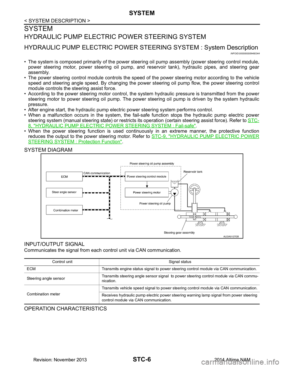
• The system is composed primarily of the power steeri ng oil pump assembly (power steering control module,
power steering motor, power steering oil pump, and reservoir tank), hydraulic pipes, and steering gear
assembly.
• The power steering control module controls the speed of the power steering motor according to the vehicle
speed and steering angle speed. By changing the power st eering oil pump flow, the power steering control
module controls the steering assist force.
• According to the power steering motor control, the sy stem hydraulic pressure is transmitted from the power
steering motor to power steering oil pump. The power steering oil pump is driven by the system hydraulic
pressure.
• After engine start, the hydraulic pump electric power steering system performs control.
• When a malfunction occurs in the system, the fail-safe function stops the hydraulic pump electric power
steering system (manual steering state) or restricts it s operation (certain steering assist force). Refer to STC-
8, "HYDRAULIC PUMP ELECTRIC POWER STEERING SYSTEM : Fail-safe".
• When the power steering function is used continuously in an extreme manner, the protective function
reduces the output to the power steering motor. Refer to STC-9, "HYDRAULIC PUMP ELECTRIC POWER
STEERING SYSTEM : Protection Function".
SYSTEM DIAGRAM
INPUT/OUTPUT SIGNAL
Communicates the signal from each control unit via CAN communication.
OPERATION CHARACTERISTICS
ALGIA0127GB
Control unit Signal status
ECM Transmits engine status signal to power steering control module via CAN communication.
Steering angle sensor Transmits steering angle sensor signal to power steering control module via CAN commu-
nication.
Combination meter Transmits vehicle speed signal to power steering control module via CAN communication.
Receives hydraulic pump electric power steering warning lamp signal from power steering
control module via CAN communication.
Revision: November 20132014 Altima NAMRevision: November 20132014 Altima NAM
Page 4173 of 4801
STC-22
< DTC/CIRCUIT DIAGNOSIS >
C1143 STEERING ANGLE SENSOR
DTC/CIRCUIT DIAGNOSIS
C1143 STEERING ANGLE SENSOR
DTC LogicINFOID:0000000009460356
DTC DETECTION LOGIC
DTC CONFIRMATION PROCEDURE
1.PRECONDITIONING
If DTC CONFIRMATION PROCEDURE has been previously conducted, always turn ignition switch OFF and
wait at least 10 seconds before conducting the next test.
>> GO TO 2.
2.DTC REPRODUCTION PROCEDURE
With CONSULT
1. Turn the ignition switch OFF to ON.
2. Perform PS self-diagnosis.
Is DTC C1143 detected?
YES >> Proceed to diagnosis procedure. Refer to STC-22, "Diagnosis Procedure".
NO >> Inspection End.
Diagnosis ProcedureINFOID:0000000009460357
1.CHECK STEERING ANGLE SENSOR CIRCUIT
Check steering angle sensor circuit. Refer to BRC-88, "Diagnosis Procedure"
.
Is the inspection result normal?
YES >> GO TO 2.
NO >> Repair or replace malfunctioning component.
2.CHECK TERMINALS AND HARNESS CONNECTORS
Check the power steering control module pin termi nals for damage or loose connection with harness connec-
tor.
Is the inspection result normal?
YES >> Power steering control module is malfunctioni ng. Replace power steering oil pump assembly.
Refer to ST-38, "Removal and Installation"
.
NO >> Repair or replace malfunctioning component.
DTC Display item Malfunction detected condition Possible cause
C1143 ST ANG SEN CIRCUIT When a malfunction is detected in steering angle
sensor. • Harness or connector
• Steering angle sensor
• Power steering control mod-
ule
Revision: November 20132014 Altima NAMRevision: November 20132014 Altima NAM
Page 4186 of 4801
STEERING WHEEL TURNING FORCE IS HEAVY OR LIGHTSTC-35
< SYMPTOM DIAGNOSIS >
C
D E
F
H I
J
K L
M A
B
STC
N
O P
6.CHECK THE POWER STEERING CONTROL MODULE SIGNAL (5)
With CONSULT
Select “STR ANG SPD” in “DATA MONITOR” of “EPS”.
Is the check result normal?
YES >> GO TO 7.
NO >> Check the steering angle sensor. Refer to STC-22, "Diagnosis Procedure"
.
7.CHECK THE POWER STEERING CONTROL MODULE SIGNAL (6)
With CONSULT
Select “ENGINE STATUS” in “DATA MONITOR” of “EPS”.
Is the display value
“RUN”?
YES >> GO TO 8.
NO >> Check the ECM. Refer to EC-77, "CONSULT Function"
.
8.CHECK THE STEERING FORCE
Check the steering force. Refer to STC-36, "Diagnosis Procedure"
.
Is the check result normal?
YES >> Inspection End.
NO >> It is possible that there is a mechani cal malfunction. Check the steering system.
Monitor item Test condition Display value
STR ANG SPD The steering wheel is not
steered. Approx. 0.0 deg/s
The steering wheel is steered. Displays steering angle speed
(deg/s)
Revision: November 20132014 Altima NAMRevision: November 20132014 Altima NAM
Page 4189 of 4801
STC-38
< SYMPTOM DIAGNOSIS >
UNBALANCE STEERING WHEEL TURNING FORCE (TORQUE VARIATION)
NO >> Check the combination meter, ABS actuator and electric unit (control unit). Refer to MWI-18,
"CONSULT Function (METER/M&A)" and BRC-33, "CONSULT Function (ABS)".
6.CHECK THE POWER STEERING CONTROL MODULE SIGNAL (5)
With CONSULT
Select “STR ANG SPD” in “DATA MONITOR” of “EPS”.
Is the check result normal?
YES >> GO TO 7.
NO >> Check the steering angle sensor. Refer to STC-22, "Diagnosis Procedure"
.
7.CHECK THE POWER STEERING CONTROL MODULE SIGNAL (6)
With CONSULT
Select “ENGINE STATUS” in “DATA MONITOR” of “EPS”.
Is the display value
“RUN”?
YES >> GO TO 8.
NO >> Check the ECM. Refer to EC-77, "CONSULT Function"
.
8.CHECK STEERING COLUMN AND STEERING GEAR
Check the steering column assembly and steering gear assembly.
• Steering column assembly. Refer to ST-46, "Steering Column"
.
• Steering gear assembly. Refer to ST-47, "Power Steering Gear"
.
Is the inspection result normal?
YES >> GO TO 9.
NO >> Repair or replace malfunctioning component.
9.CHECK STEERING WHEEL TURNING FORCE
Check the steering wheel turning force. Refer to STC-34, "Diagnosis Procedure"
.
Is the inspection result normal?
YES >> Inspection End.
NO >> Check the steering wheel turning force for mechanical malfunction. Refer to STC-34, "Diagnosis
Procedure".
Monitor item Test condition Display value
STR ANG SPD The steering wheel is not turn-
ing. Approx. 0.0 deg/s
The steering wheel is being
turned. Displays steering angle speed
(deg/s)
Revision: November 20132014 Altima NAMRevision: November 20132014 Altima NAM
Page 4192 of 4801
STR-2
< PRECAUTION >
PRECAUTIONS
PRECAUTION
PRECAUTIONS
Precaution for Supplemental Restraint System (SRS) "AIR BAG" and "SEAT BELT
PRE-TENSIONER"
INFOID:0000000009951694
The Supplemental Restraint System such as “A IR BAG” and “SEAT BELT PRE-TENSIONER”, used along
with a front seat belt, helps to reduce the risk or severi ty of injury to the driver and front passenger for certain
types of collision. Information necessary to service the system safely is included in the SR and SB section of
this Service Manual.
WARNING:
• To avoid rendering the SRS inopera tive, which could increase the risk of personal injury or death in
the event of a collision which would result in air bag inflation, all maintenance must be performed by
an authorized NISS AN/INFINITI dealer.
• Improper maintenance, including in correct removal and installation of the SRS, can lead to personal
injury caused by unintent ional activation of the system. For re moval of Spiral Cable and Air Bag
Module, see the SR section.
• Do not use electrical test equipmen t on any circuit related to the SRS unless instructed to in this
Service Manual. SRS wiring harn esses can be identified by yellow and/or orange harnesses or har-
ness connectors.
PRECAUTIONS WHEN USING POWER TOOLS (AIR OR ELECTRIC) AND HAMMERS
WARNING:
• When working near the Airbag Diagnosis Sensor Unit or other Airbag System sensors with the Igni-
tion ON or engine running, DO NOT use air or electri c power tools or strike near the sensor(s) with a
hammer. Heavy vibration could activate the sensor( s) and deploy the air bag(s), possibly causing
serious injury.
• When using air or electric power tools or hammers , always switch the Ignition OFF, disconnect the
battery and wait at least three minutes before performing any service.
Revision: November 20132014 Altima NAMRevision: November 20132014 Altima NAM
Page 4216 of 4801

TM-1
TRANSMISSION & DRIVELINE
CEF
G H
I
J
K L
M
SECTION TM
A
B
TM
N
O P
CONTENTS
TRANSAXLE & TRANSMISSION
CVT: RE0F10D
PRECAUTION ................ ...............................
9
PRECAUTIONS .............................................. .....9
Precaution for Supplemental Restraint System
(SRS) "AIR BAG" and "SEAT BELT PRE-TEN-
SIONER" ............................................................. ......
9
Precaution for Procedure without Cowl Top Cover ......9
Precaution for TCM and Transaxle Assembly Re-
placement ............................................................ ......
9
General Precautions ...............................................10
On Board Diagnosis (OBD) System of CVT and
Engine ................................................................. ....
11
Removal and Installation Procedure for CVT Unit
Connector ............................................................ ....
11
PREPARATION ...........................................13
PREPARATION .............................................. ....13
Special Service Tools .......................................... ....13
Commercial Service Tools ......................................13
SYSTEM DESCRIPTION .............................14
COMPONENT PARTS ................................... ....14
CVT CONTROL SYSTEM .........................................14
CVT CONTROL SYSTEM : Component Parts Lo-
cation ................................................................... ....
14
CVT CONTROL SYSTEM : TCM ............................16
CVT CONTROL SYSTEM : Transmission Range
Switch .................................................................. ....
16
CVT CONTROL SYSTEM : Primary Speed Sen-
sor ....................................................................... ....
16
CVT CONTROL SYSTEM : Output Speed Sensor ....16
CVT CONTROL SYSTEM : In put Speed Sensor ....17
CVT CONTROL SYSTEM : CVT Fluid Tempera-
ture Sensor .......................................................... ....
17
CVT CONTROL SYSTEM : Primary Pressure
Sensor ................................................................. ....
18
CVT CONTROL SYSTEM : Secondary Pressure
Sensor ................................................................. ....
18
CVT CONTROL SYSTEM : Primary Pressure So-
lenoid Valve ......................................................... ....
19
CVT CONTROL SYSTEM : Secondary Pressure
Solenoid Valve ..................................................... ....
19
CVT CONTROL SYSTEM : Select Solenoid Valve
....
19
CVT CONTROL SYSTEM : Torque Converter
Clutch Solenoid Valve ......................................... ....
19
CVT CONTROL SYSTEM : Line Pressure Sole-
noid Valve ............................................................ ....
20
CVT CONTROL SYSTEM : Overdrive Control
Switch .................................................................. ....
20
CVT CONTROL SYSTEM : O/D OFF Indicator
Lamp .................................................................... ....
20
CVT CONTROL SYSTEM : Shift Position Indica-
tor ........................................................................ ....
20
SHIFT LOCK SYSTEM ..............................................20
SHIFT LOCK SYSTEM : Component Parts Loca-
tion ....................................................................... ....
21
STRUCTURE AND OPERATION .....................22
TRANSAXLE .......................................................... ....22
TRANSAXLE : Cross-Sectional View ......................22
TRANSAXLE : Operation Stat us .............................23
TRANSAXLE : Transaxle Me chanism .....................23
TRANSAXLE : Oil Pressure System .......................26
TRANSAXLE : Component De scription ...................27
FLUID COOLER & FLUID WARMER SYSTEM .... ....27
FLUID COOLER & FLUID WARMER SYSTEM :
System Description .............................................. ....
28
SHIFT LOCK SYSTEM ..............................................28
SHIFT LOCK SYSTEM : Syst em Description ..........28
SYSTEM ...................... ......................................30
CVT CONTROL SYSTEM ..... .....................................30
CVT CONTROL SYSTEM : S ystem Description .....30
Revision: November 20132014 Altima NAMRevision: November 20132014 Altima NAM
Page 4217 of 4801

TM-2
CVT CONTROL SYSTEM : Fail-safe .................. ...31
CVT CONTROL SYSTEM : Protection Control ... ...34
LINE PRESSURE CONTROL ................................ ...35
LINE PRESSURE CONTROL : System Descrip-
tion ....................................................................... ...
35
SHIFT CONTROL ................................................... ...35
SHIFT CONTROL : System Description .................36
SELECT CONTROL ............................................... ...37
SELECT CONTROL : System Description .............38
LOCK-UP CONTROL ............................................. ...38
LOCK-UP CONTROL : System Description ...........38
ON BOARD DIAGNOSTIC (OBD) SYSTEM .....40
Description ........................................................... ...40
Function of OBD .....................................................40
DIAGNOSIS SYSTEM (TCM) ............................41
DIAGNOSIS DESCRIPTION .................................. ...41
DIAGNOSIS DESCRIPTION : 1 Trip Detection Di-
agnosis and 2 Trip Detection Diagnosis .............. ...
41
DIAGNOSIS DESCRIPTION : DTC and DTC of
1st Trip ................................................................. ...
41
DIAGNOSIS DESCRIPTION : Malfunction Indica-
tor Lamp (MIL) ..................................................... ...
41
DIAGNOSIS DESCRIPTION : Counter System .....41
CONSULT Function ................................................43
ECU DIAGNOSIS INFORMATION ..............49
TCM ................................................................. ...49
Reference Value .................................................. ...49
Fail-safe ..................................................................56
Protection Control ...................................................59
DTC Inspection Priority Chart .................................59
DTC Index ..............................................................60
WIRING DIAGRAM .....................................62
CVT CONTROL SYSTEM ............................... ...62
Wiring diagram .................................................... ...62
CVT SHIFT LOCK SYSTEM ........................... ...73
Wiring diagram .................................................... ...73
BASIC INSPECTION ...................................77
DIAGNOSIS AND REPAIR WORK FLOW ..... ...77
Flowchart of Trouble Diagnosis ........................... ...77
Question sheet .......................................................78
ADDITIONAL SERVICE WHEN REPLACING
TCM ................................................................. ...
80
Description ........................................................... ...80
Work Procedure ......................................................80
ADDITIONAL SERVICE WHEN REPLACING
TRANSAXLE ASSEMBLY ............................. ...
81
Description ........................................................... ...81
Work Procedure ................................................... ...81
CVT FLUID ........................................................83
Replacement ........................................................ ...83
Adjustment ..............................................................84
STALL TEST .....................................................86
Work Procedure ................................................... ...86
CVT POSITION ..................................................87
Inspection ............................................................. ...87
Adjustment ..............................................................87
DTC/CIRCUIT DIAGNOSIS ........................88
U0073 COMMUNICATION BUS A OFF ......... ...88
DTC Logic ............................................................ ...88
Diagnosis Procedure ...............................................88
U0100 LOST COMMUNICATION (ECM A) .......89
DTC Logic ............................................................ ...89
Diagnosis Procedure ...............................................89
U0140 LOST COMMUNICATION (BCM) ..........90
DTC Logic ............................................................ ...90
Diagnosis Procedure ...............................................90
U0141 LOST COMMUNICATION (BCM A) ......91
DTC Logic ............................................................ ...91
Diagnosis Procedure ...............................................91
U0155 LOST COMMUNICATION (IPC) ............92
DTC Logic ............................................................ ...92
Diagnosis Procedure ...............................................92
U0300 CAN COMMUNICATION DATA ............93
DTC Logic ............................................................ ...93
Diagnosis Procedure ...............................................93
U1000 CAN COMM CIRCUIT ............................94
Description ........................................................... ...94
DTC Logic ...............................................................94
Diagnosis Procedure ...............................................94
U1117 LOST COMMUNICATION (ABS) ...........95
DTC Logic ............................................................ ...95
Diagnosis Procedure ...............................................95
P062F EEPROM ................................................96
Description ........................................................... ...96
DTC Logic ...............................................................96
Diagnosis Procedure ...............................................96
P0705 TRANSMISSION RANGE SENSOR A ...97
DTC Logic ............................................................ ...97
Diagnosis Procedure ...............................................97
Component Inspection ..........................................101
P0706 TRANSMISSION RANGE SENSOR A ..103
DTC Logic ............................................................ .103
Diagnosis Procedure .............................................103
Component Inspection ..........................................105
Revision: November 20132014 Altima NAMRevision: November 20132014 Altima NAM
Page 4218 of 4801

TM-3
CEF
G H
I
J
K L
M A
B
TM
N
O P
P0711 TRANSMISSION FLUID TEMPERA-
TURE SENSOR A .......................................... ..
106
DTC Logic ........................................................... ..106
Diagnosis Procedure .............................................107
P0712 TRANSMISSION FLUID TEMPERA-
TURE SENSOR A .......................................... ..
110
DTC Logic ........................................................... ..110
Diagnosis Procedure .............................................110
Component Inspection ..........................................110
P0713 TRANSMISSION FLUID TEMPERA-
TURE SENSOR A .......................................... ..
112
DTC Logic ........................................................... ..112
Diagnosis Procedure .............................................112
Component Inspection ..........................................113
P0715 INPUT SPEED SENSOR A ...................114
DTC Logic ........................................................... ..114
Diagnosis Procedure .............................................115
P0717 INPUT SPEED SENSOR A ...................117
DTC Logic ........................................................... ..117
Diagnosis Procedure .............................................118
P0740 TORQUE CONVERTER ........................120
DTC Logic ........................................................... ..120
Diagnosis Procedure .............................................121
P0743 TORQUE CONVERTER ........................122
DTC Logic ........................................................... ..122
Diagnosis Procedure .............................................123
P0744 TORQUE CONVERTER ........................124
DTC Logic ........................................................... ..124
Diagnosis Procedure .............................................125
P0746 PRESSURE CONTROL SOLENOID A ..126
DTC Logic ........................................................... ..126
Diagnosis Procedure .............................................127
P0776 PRESSURE CONTROL SOLENOID B ..128
DTC Logic ........................................................... ..128
Diagnosis Procedure .............................................129
P0778 PRESSURE CONTROL SOLENOID B ..130
DTC Logic ........................................................... ..130
Diagnosis Procedure .............................................130
P0779 PRESSURE CONTROL SOLENOID B ..132
DTC Logic ........................................................... ..132
Diagnosis Procedure .............................................132
P0841 TRANSMISSION FLUID PRESSURE
SEN/SW A ...................................................... ..
134
DTC Logic ........................................................... ..134
Diagnosis Procedure .............................................134
P0847 TRANSMISSION FLUID PRESSURE
SEN/SW B ...................................................... ..
135
DTC Logic ........................................................... ..135
Diagnosis Procedure ........................................... ..135
P0848 TRANSMISSION FLUID PRESSURE
SEN/SW B .......................................................
137
DTC Logic ............................................................ ..137
Diagnosis Procedure .............................................137
P084C TRANSMISSION FLUID PRESSURE
SEN/SW H .......................................................
139
DTC Logic ............................................................ ..139
Diagnosis Procedure .............................................139
P084D TRANSMISSION FLUID PRESSURE
SEN/SW H .......................................................
141
DTC Logic ............................................................ ..141
Diagnosis Procedure .............................................141
P0863 TCM COMMUNICATION .....................143
DTC Logic ..............................................................143
Diagnosis Procedure .............................................143
P0890 TCM ......................................................144
DTC Logic ..............................................................144
Diagnosis Procedure .............................................144
P0962 PRESSURE CONTROL SOLENOID A .145
DTC Logic ............................................................ ..145
Diagnosis Procedure .............................................145
P0963 PRESSURE CONTROL SOLENOID A .147
DTC Logic ............................................................ ..147
Diagnosis Procedure .............................................147
P0965 PRESSURE CONTROL SOLENOID B .149
DTC Logic ............................................................ ..149
Diagnosis Procedure .............................................150
P0966 PRESSURE CONTROL SOLENOID B .151
DTC Logic ............................................................ ..151
Diagnosis Procedure .............................................151
P0967 PRESSURE CONTROL SOLENOID B .153
DTC Logic ............................................................ ..153
Diagnosis Procedure .............................................153
P2765 INPUT SPEED SENSOR B ..................155
DTC Logic ..............................................................155
Diagnosis Procedure .............................................156
P2813 SELECT SOLENOID ...........................158
DTC Logic ..............................................................158
Diagnosis Procedure .............................................159
P2814 SELECT SOLENOID ...........................160
DTC Logic ..............................................................160
Diagnosis Procedure .............................................160
P2815 SELECT SOLENOID ...........................162
DTC Logic ..............................................................162
Diagnosis Procedure .............................................162
Revision: November 20132014 Altima NAMRevision: November 20132014 Altima NAM
Page 4219 of 4801

TM-4
MAIN POWER SUPPLY AND GROUND CIR-
CUIT ................................................................ .
164
Diagnosis Procedure ........................................... ..164
OVERDRIVE CONTROL SWITCH ..................166
Component Function Check ................................ ..166
Diagnosis Procedure .............................................166
Component Inspection ...........................................167
OD OFF INDICATOR LAMP ............................168
Component Function Check ................................ ..168
Diagnosis Procedure .............................................168
SHIFT POSITION INDICATOR CIRCUIT ........169
Component Parts Function Inspection ................ ..169
Diagnosis Procedure .............................................169
SHIFT LOCK SYSTEM ................................... .170
Component Function Check ................................ ..170
Diagnosis Procedure .............................................170
Component Inspection (Shift Lock Solenoid) ........172
Component Inspection (Park Position Switch) ......172
Component Inspection (Stop Lamp Switch) ..........173
SYMPTOM DIAGNOSIS ............................174
CVT CONTROL SYSTEM ............................... .174
Symptom Table ................................................... ..174
PERIODIC MAINTENANCE ..................... ..178
CVT FLUID ...................................................... .178
Inspection ............................................................ ..178
REMOVAL AND INSTALLATION ..............179
CVT SHIFT SELECTOR ................................. .179
Exploded View ..................................................... ..179
Removal and Installation .......................................179
Inspection ..............................................................180
CONTROL CABLE ..........................................181
Exploded View ..................................................... ..181
Removal and Installation .......................................181
Inspection and Adjustment ....................................182
TCM ..................................................................183
Exploded View ..................................................... ..183
Removal and Installation .......................................183
Adjustment .............................................................184
AIR BREATHER HOSE ...................................185
Removal and Installation ..................................... ..185
CONTROL VALVE ...........................................186
Exploded View ..................................................... ..186
Removal and Installation .......................................187
Inspection ..............................................................191
INPUT SPEED SENSOR .................................192
Exploded View ..................................................... ..192
Removal and Installation .......................................192
Inspection and Adjustment ................................... .192
PRIMARY SPEED SENSOR .......................... ..194
Exploded View ..................................................... .194
Removal and Installation .......................................194
Inspection and Adjustment ................................... .194
OUTPUT SPEED SENSOR ..............................196
Exploded View ..................................................... .196
Removal and Installation .......................................196
Inspection and Adjustment ................................... .196
DIFFERENTIAL SIDE OIL SEAL .....................197
Exploded View ..................................................... .197
Removal and Installation .......................................197
Inspection and Adjustment ................................... .198
CVT OIL WARMER SYSTEM ...........................199
WATER HOSE ........................................................ .199
WATER HOSE : Exploded View ...........................199
WATER HOSE : Removal and Installation ...........199
WATER HOSE : Inspection ..................................201
CVT FLUID COOLER HOSE .................................. .201
CVT FLUID COOLER HOSE : Exploded View .....201
CVT FLUID COOLER HOSE : Removal and In-
stallation ............................................................... .
202
CVT FLUID COOLER HOSE : Inspection .............203
CVT OIL WARMER ................................................ .203
CVT OIL WARMER : Exploded View ....................203
CVT OIL WARMER : Removal and Installation ....203
CVT OIL WARMER : Inspection .......................... .204
PLUG ................................................................205
Description ........................................................... .205
Exploded View ......................................................205
Removal and Installation .......................................205
Inspection and Adjustment ................................... .205
UNIT REMOVAL AND INSTALLATION ...206
TRANSAXLE ASSEMBLY ............................. ..206
Exploded View ..................................................... .206
Removal and Installation .......................................206
Inspection and Adjustment ................................... .208
UNIT DISASSEMBLY AND ASSEMBLY ..209
TORQUE CONVERTER AND CONVERTER
HOUSING OIL SEAL ...................................... ..
209
Exploded View ..................................................... .209
Disassembly ..........................................................209
Assembly ..............................................................209
Inspection ..............................................................210
SERVICE DATA AND SPECIFICATIONS
(SDS) ............... ..........................................
212
SERVICE DATA AND SPECIFICATIONS
(SDS) .............................................................. ..
212
Revision: November 20132014 Altima NAMRevision: November 20132014 Altima NAM
Page 4220 of 4801

TM-5
CEF
G H
I
J
K L
M A
B
TM
N
O P
General Specification ..........................................
..
212
Shift Characteristics ..............................................212
Stall Speed ............................................................212
Torque Converter ..................................................212
Heater Thermostat ................................................212
CVT: RE0F10E
PRECAUTION ................ ............................
213
PRECAUTIONS .............................................. ..213
Precaution for Supplemental Restraint System
(SRS) "AIR BAG" and "SEAT BELT PRE-TEN-
SIONER" ............................................................. ..
213
Precaution for Procedure without Cowl Top Cover ..213
Precaution for TCM and Transaxle Assembly Re-
placement ............................................................ ..
213
General Precautions .............................................214
On Board Diagnosis (OBD) System of CVT and
Engine ................................................................. ..
215
Removal and Installation Procedure for CVT Unit
Connector ............................................................ ..
215
PREPARATION .........................................217
PREPARATION .............................................. ..217
Special Service Tools .......................................... ..217
Commercial Service Tools ....................................217
SYSTEM DESCRIPTION ...........................218
COMPONENT PARTS ................................... ..218
CVT CONTROL SYSTEM .......................................218
CVT CONTROL SYSTEM : Component Parts Lo-
cation ................................................................... ..
218
CVT CONTROL SYSTEM : TCM ..........................219
CVT CONTROL SYSTEM : Transmission Range
Switch .................................................................. ..
219
CVT CONTROL SYSTEM : Primary Speed Sen-
sor ....................................................................... ..
219
CVT CONTROL SYSTEM : Output Speed Sensor ..220
CVT CONTROL SYSTEM : Input Speed Sensor ..220
CVT CONTROL SYSTEM : CVT Fluid Tempera-
ture Sensor .......................................................... ..
221
CVT CONTROL SYSTEM : Primary Pressure
Sensor ................................................................. ..
221
CVT CONTROL SYSTEM : Secondary Pressure
Sensor ................................................................. ..
222
CVT CONTROL SYSTEM : Primary Pressure So-
lenoid Valve ......................................................... ..
222
CVT CONTROL SYSTEM : Secondary Pressure
Solenoid Valve .................................................... ..
222
CVT CONTROL SYSTEM : Select Solenoid Valve
..
223
CVT CONTROL SYSTEM : Torque Converter
Clutch Solenoid Valve ......................................... ..
223
CVT CONTROL SYSTEM : Line Pressure Sole-
noid Valve ........................................................... ..
223
CVT CONTROL SYSTEM : Paddle Shifter ...........223
CVT CONTROL SYSTEM : Shift Position Indica-
tor ........................................................................ ..
223
SHIFT LOCK SYSTEM ............................................223
SHIFT LOCK SYSTEM : Component Parts Loca-
tion ....................................................................... ..
224
STRUCTURE AND OPERATION ...................225
TRANSAXLE .......................................................... ..225
TRANSAXLE : Cross-Sectional View ....................225
TRANSAXLE : Operation Stat us ...........................226
TRANSAXLE : Transaxle Me chanism ...................226
TRANSAXLE : Oil Pressure System .....................228
TRANSAXLE : Component De scription .................229
FLUID COOLER & FLUID WARMER SYSTEM .... ..229
FLUID COOLER & FLUID WARMER SYSTEM :
System Description .............................................. ..
230
SHIFT LOCK SYSTEM ............................................230
SHIFT LOCK SYSTEM : Syst em Description ........230
SYSTEM ...................... ....................................232
CVT CONTROL SYSTEM ..... ...................................232
CVT CONTROL SYSTEM : S ystem Description ...232
CVT CONTROL SYSTEM : Fa il-safe ....................233
CVT CONTROL SYSTEM : Pr otection Control .....236
LINE PRESSURE CONTROL ......................... .........237
LINE PRESSURE CONTROL : System Descrip-
tion ....................................................................... ..
237
SHIFT CONTROL .................................................. ..237
SHIFT CONTROL : System Description ................238
SELECT CONTROL ............................................... ..239
SELECT CONTROL : System Description ............239
LOCK-UP CONTROL ............................................ ..240
LOCK-UP CONTROL : System Description ..........240
ON BOARD DIAGNOSTIC (OBD) SYSTEM ..242
Description .............................................................242
Function of OBD ....................................................242
DIAGNOSIS SYSTEM (TCM) ..........................243
DIAGNOSIS DESCRIPTION .................................. ..243
DIAGNOSIS DESCRIPTION : 1 Trip Detection Di-
agnosis and 2 Trip Detection Diagnosis .............. ..
243
DIAGNOSIS DESCRIPTION : DTC and DTC of
1st Trip ................................................................. ..
243
DIAGNOSIS DESCRIPTION : Malfunction Indica-
tor Lamp (MIL) ..................................................... ..
243
DIAGNOSIS DESCRIPTION : Counter System ....243
CONSULT Function ............................................. ..245
ECU DIAGNOSIS INFORMATION ............251
TCM .................................................................251
Reference Value .................................................. ..251
Revision: November 20132014 Altima NAMRevision: November 20132014 Altima NAM