spare tire NISSAN TEANA 2014 Service Manual
[x] Cancel search | Manufacturer: NISSAN, Model Year: 2014, Model line: TEANA, Model: NISSAN TEANA 2014Pages: 4801, PDF Size: 51.2 MB
Page 6 of 4801
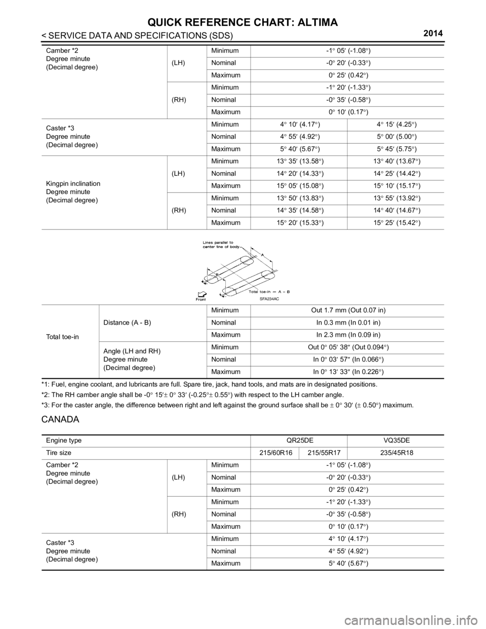
< SERVICE DATA AND SPECIFICATIONS (SDS) 2014
QUICK REFERENCE CHART: ALTIMA
*1: Fuel, engine coolant, and lubricants are full. Spare tire, jack, hand tools, and mats are in designated positions.
*2: The RH camber angle shall be -0
° 15 ′± 0 ° 33 ′ (-0.25 °± 0.55° ) with respect to the LH camber angle.
*3: For the caster angle, the difference between right and left against the ground surface shall be ± 0 ° 30 ′ ( ± 0.50° ) maximum.
CANADA
Camber *2
Degree minute
(Decimal degree) (LH)Minimum
-1° 05 ′ (-1.08 °)
Nominal -0° 20 ′ (-0.33 °)
Maximum 0° 25 ′ (0.42 °)
(RH) Minimum
-1° 20 ′ (-1.33 °)
Nominal -0° 35 ′ (-0.58 °)
Maximum 0° 10 ′ (0.17 °)
Caster *3
Degree minute
(Decimal degree) Minimum
4° 10 ′ (4.17 °)4 ° 15 ′ (4.25 °)
Nominal 4° 55 ′ (4.92 °)5 ° 00 ′ (5.00 °)
Maximum 5° 40 ′ (5.67 °)5 ° 45 ′ (5.75 °)
Kingpin inclination
Degree minute
(Decimal degree) (LH)
Minimum
13° 35 ′ (13.58 °)1 3° 40 ′ (1
3.67 °)
Nominal 14° 20 ′ (14.33 °)1 4° 25 ′ (14.42 °)
Maximum 15° 05 ′ (15.08 °)1 5° 10 ′ (15.17 °)
(RH) Minimum
13° 50 ′ (13.83 °)1 3° 55 ′ (13.92 °)
Nominal 14° 35 ′ (14.58 °)1 4° 40 ′ (14.67 °)
Maximum 15° 20 ′ (15.33 °)1 5° 25 ′ (15.42 °)
Total toe-in Distance (A - B)
Minimum
Out 1.7 mm (Out 0.07 in)
Nominal In 0.3 mm (In 0.01 in)
Maximum In 2.3 mm (In 0.09 in)
Angle (LH and RH)
Degree minute
(Decimal degree) Minimum
Out 0° 05′ 38 ″ (Out 0.094° )
Nominal In 0° 03 ′ 57 ″ (In 0.066 °)
Maximum In 0° 13′ 33 ″ (In 0.2
26 °)
SFA234AC
Engine type QR25DEVQ35DE
Tire size 215/60R16 215/55R17235/45R18
Camber *2
Degree minute
(Decimal degree) (LH)Minimum
-1° 05 ′ (-1.08 °)
Nominal -0° 20 ′ (-0.33 °)
Maximum 0° 25 ′ (0.42 °)
(RH) Minimum
-1° 20 ′ (-1.33 °)
Nominal -0° 35 ′ (-0.58 °)
Maximum 0° 10 ′ (0.17 °)
Caster *3
Degree minute
(Decimal degree) Minimum
4° 10 ′ (4.17 °)
Nominal 4° 55 ′ (4.92 °)
Maximum 5° 40 ′ (5.67 °)
Page 7 of 4801
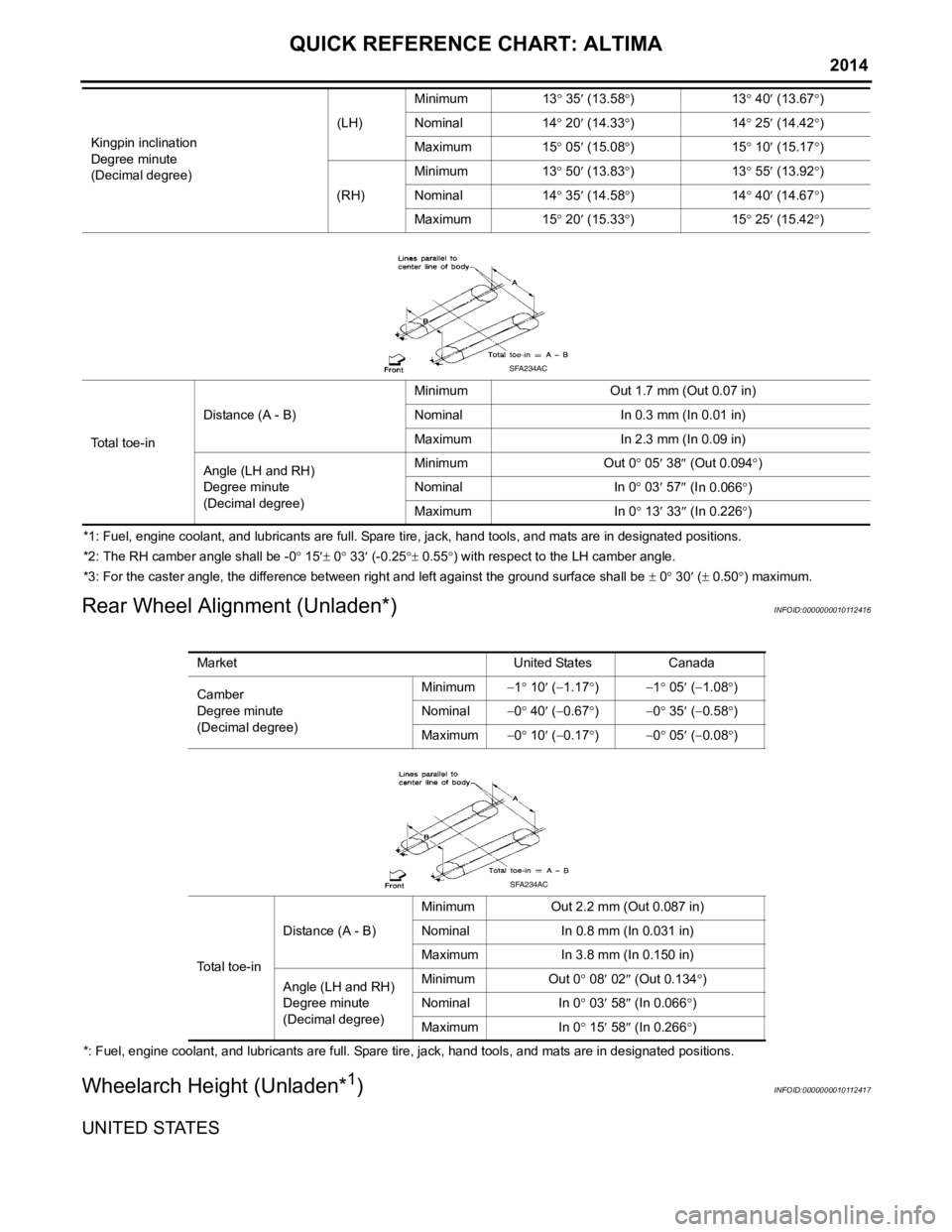
QUICK REFERENCE CHART: ALTIMA
2014
*1: Fuel, engine coolant, and lubricants are full. Spare tire, jack, hand tools, and mats are in designated positions.
*2: The RH camber angle shall be -0° 15 ′± 0 ° 33′ (-0.25 °± 0.55 °) with respect to the LH camber angle.
*3: For the caster angle, the difference between right and left against the ground surface shall be ± 0 ° 30 ′ ( ± 0.50 °) maximum.
Rear Wheel Alignment (Unladen*)INFOID:0000000010112416
*: Fuel, engine coolant, and lubricants are full. Spare tire, jack, hand tools, and mats are in designated positions.
Wheelarch Height (Unladen*1)INFOID:0000000010112417
UNITED STATES
Kingpin inclination
Degree minute
(Decimal degree) (LH)
Minimum
13° 35 ′ (13.58 °)1 3° 40 ′ (13.67 °)
Nominal 14° 20 ′ (14.33 °)1 4° 25 ′ (14.42 °)
Maximum 15° 05 ′ (15.08 °)1 5° 10 ′ (15.17 °)
(RH) Minimum
13° 50 ′ (13.83 °)1 3° 55 ′ (13.92 °)
Nominal 14° 35 ′ (14.58 °)1 4° 40 ′ (14.67 °)
Maximum 15° 20 ′ (15.33 °)1 5° 25 ′ (15.42 °)
To t a l t o e - i n Distance (A - B)
Minimum
Out 1.7 mm (Out 0.07 in)
Nominal In 0.3 mm (In 0.01 in)
Maximum In 2.3 mm (In 0.09 in)
Angle (LH and RH)
Degree minute
(Decimal degree) Minimum
Out 0° 05 ′ 38 ″ (Out 0.094 °)
Nominal In 0° 03 ′ 57 ″ (I
n 0.066 °)
Maximum In 0° 13 ′ 33 ″ (In 0.226 °)
SFA234AC
Market United StatesCanada
Camber
Degree minute
(Decimal degree) Minimum
−1° 10 ′ ( −1.17 °) −1 ° 05 ′ ( −1.08° )
Nominal −0° 40 ′ ( −0.67 °) −0 ° 35 ′ ( −0.58° )
Maximum −0° 10 ′ ( −0.17 °) −0 ° 05 ′ ( −0.08° )
Total toe-in Distance (A - B)
Minimum
Out 2.2 mm (Out 0.087 in)
Nominal In 0.8 mm (In 0.031 in)
Maximum In 3.8 mm (In 0.150 in)
Angle (LH and RH)
Degree minute
(Decimal degree) Minimum
Out 0° 08′ 02 ″ (Out 0.134° )
Nominal In 0° 03 ′ 58 ″ (In 0.066 °)
Maximum In 0° 15′ 58 ″ (In 0.266 °)
SFA234AC
Page 8 of 4801
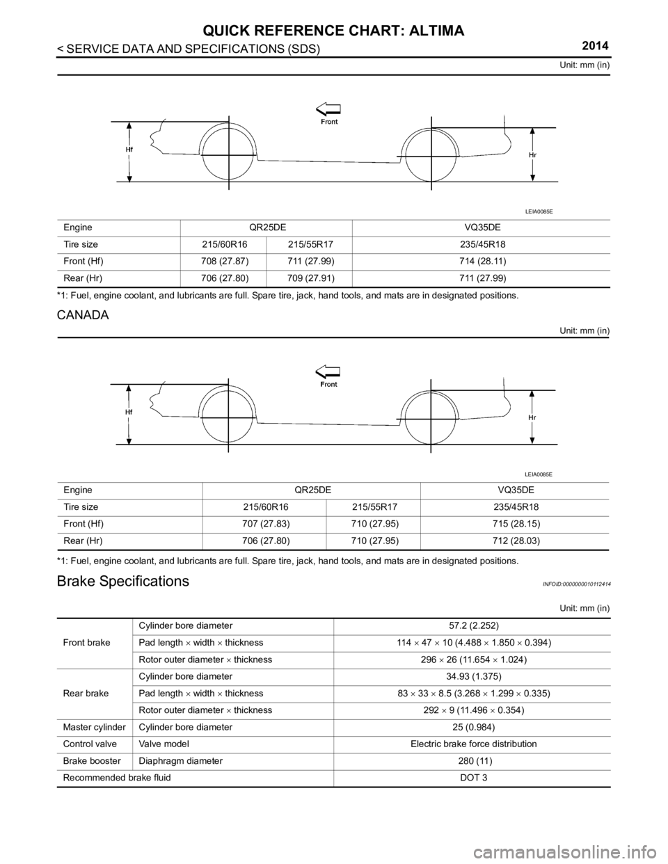
< SERVICE DATA AND SPECIFICATIONS (SDS) 2014
QUICK REFERENCE CHART: ALTIMA
Unit: mm (in)
*1: Fuel, engine coolant, and lubricants are full. Spare tire, jack, hand tools, and mats are in designated positions.
CANADA
Unit: mm (in)
*1: Fuel, engine coolant, and lubricants are full. Spare tire, jack, hand tools, and mats are in designated positions.
Brake SpecificationsINFOID:0000000010112414
Unit: mm (in)
Engine
QR25DE VQ35DE
Tire size 215/60R16 215/55R17 235/45R18
Front (Hf) 708 (27.87) 711 (27.99) 714 (28.11)
Rear (Hr) 706 (27.80) 709 (27.91) 711 (27.99)
LEIA0085E
EngineQR25DEVQ35DE
Tire size 215/60R16215/55R17 235/45R18
Front (Hf) 707 (27.83)710 (27.95) 715 (28.15)
Rear (Hr) 706 (27.80)710 (27.95) 712 (28.03)
LEIA0085E
Front brakeCylinder bore diameter
57.2 (2.252)
Pad length × width × thickness 114 × 47 × 10 (4.488 × 1.850 × 0.394)
Rotor outer diameter × thickness 296 × 26 (11.654 × 1.024)
Rear brake Cylinder bore diameter
34.93 (1.375)
Pad length × width × thickness 83 × 33 × 8.5 (3.268 × 1.299 × 0.335)
Rotor outer diameter × thickness 292 × 9 (11.496 × 0.354)
Master cylinder Cylinder bore diameter 25 (0.984)
Control valve Valve model Electric brake force distribution
Brake booster Diaphragm diameter 280 (11)
Recommended brake fluid DOT 3
Page 649 of 4801
![NISSAN TEANA 2014 Service Manual
DAS-216
< SYMPTOM DIAGNOSIS >[BSW]
NORMAL OPERATING CONDITION
NORMAL OPERATING CONDITION
DescriptionINFOID:0000000009464875
PRECAUTIONS FOR BLIND SPOT WARNING (BSW)
• The Blind Spot Warning system NISSAN TEANA 2014 Service Manual
DAS-216
< SYMPTOM DIAGNOSIS >[BSW]
NORMAL OPERATING CONDITION
NORMAL OPERATING CONDITION
DescriptionINFOID:0000000009464875
PRECAUTIONS FOR BLIND SPOT WARNING (BSW)
• The Blind Spot Warning system](/img/5/57390/w960_57390-648.png)
DAS-216
< SYMPTOM DIAGNOSIS >[BSW]
NORMAL OPERATING CONDITION
NORMAL OPERATING CONDITION
DescriptionINFOID:0000000009464875
PRECAUTIONS FOR BLIND SPOT WARNING (BSW)
• The Blind Spot Warning system is not a replacem
ent for proper driving procedure and are not designed to
prevent contact with vehicles or objects. When c hanging lanes, always use the side and rear mirrors and
turn and look in the direction driver will move to ensure it is safe to change lanes. Never rely solely on the
Blind Spot Warning system.
• The Blind Spot Warning system may not provide a warn ing for vehicles that pass through the detection zone
quickly.
• Do not use the Blind Spot Warning system when towing a trailer.
• Excessive noise (e.g., audio system volume, open v ehicle window) will interfere with the chime sound, and it
may not be heard.
• The rear view camera may not be able to detect and activate Blind Spot Warning when certain objects are present such as:
- Pedestrians, bicycles, animals.
- Several types of vehicles such as motorcycles.
- Oncoming vehicles.
- Vehicles remaining in the detection zone when driver accelerates from a stop.
- A vehicle merging into an adjacent lane at a speed approximately the same as vehicle.
- A vehicle approaching rapidly from behind.
- Another vehicle which overtakes this vehicle rapidly.
• Severe weather or road spray conditions may reduce the abi lity of the rear view camera to detect other vehi-
cles.
• The rear view camera detection zone is designed based on a standard lane width. When driving in a wider
lane, the rear view camera may not detect vehicles in an adjacent lane. When driving in a narrow lane, the
rear view camera may detect vehicles driving two lanes away.
• The rear view camera is designed to ignore most stationary objects, however objects such as guardrails,
walls, foliage and parked vehicles may occasionally be detected. This is a normal operating condition.
PRECAUTIONS FOR BLIND SPOT WARNING
• Do not use the Blind Spot Warning system under the following conditions because the system may not func-
tion properly:
- During bad weather (e.g., rain, fog, snow, wind, etc.)
- When driving on slippery roads, such as on ice or snow, etc.
- When driving on winding or uneven roads.
- When there is a lane closure due to road repairs.
- When driving in a makeshift lane.
- When driving on roads where the lane width is too narrow.
- When driving with a tire that is not within normal tire c onditions (e.g., tire wear, low tire pressure, installation
of spare tire, tire chains, non-standard wheels).
- When the vehicle is equipped with non-original brake parts or suspension parts.
• The rear view camera may not detect lane markers in the following situations and the Blind Spot Warning
system may not operate properly:
- On roads where there are multiple parallel lane marker s; lane markers that are faded or not painted clearly;
yellow painted lane markers; nonstandard lane markers; lane markers covered with water, dirt, snow, etc.
- On roads where discontinued lane markers are still detectable.
- On roads where there are sharp curves.
- On roads where there are sharply c ontrasting objects, such as shadows, snow, water, wheel ruts, seams or
lines remaining after road repairs.
- On roads where the traveling lane merges or separates.
- When the vehicle traveling direction does not align with the lane markers.
- When rain, snow or dirt adheres to the lens of a the rear view camera unit.
- When a sudden change in brightness occurs. (e.g., when the vehicle enters or exits a tunnel or under a
bridge.)
- When steering quickly.
- When the hazard warning flashers are operated.
- When driving on a curve at a high speed.
Revision: November 20132014 Altima NAMRevision: November 20132014 Altima NAM
Page 663 of 4801
![NISSAN TEANA 2014 Service Manual
DAS-230
< SYSTEM DESCRIPTION >[MOD]
SYSTEM
• Moving Object Detection braking will not operate or
will stop operating and only a warning chime will sound
under the following conditions:
- When driv NISSAN TEANA 2014 Service Manual
DAS-230
< SYSTEM DESCRIPTION >[MOD]
SYSTEM
• Moving Object Detection braking will not operate or
will stop operating and only a warning chime will sound
under the following conditions:
- When driv](/img/5/57390/w960_57390-662.png)
DAS-230
< SYSTEM DESCRIPTION >[MOD]
SYSTEM
• Moving Object Detection braking will not operate or
will stop operating and only a warning chime will sound
under the following conditions:
- When driving with a tire that is not within normal tire conditions (pressure, wear, chain, spare, etc.)
- When the vehicle is equipped with non-original brake parts or suspension parts.
• Do not use the MOD system when towing a trailer.
• Excessive noise such as the audio system will inte rfere with the chime sound, and it may not be heard.
Revision: November 20132014 Altima NAMRevision: November 20132014 Altima NAM
Page 665 of 4801
![NISSAN TEANA 2014 Service Manual
DAS-232
< SYSTEM DESCRIPTION >[MOD]
HANDLING PRECAUTION
HANDLING PRECAUTION
Precautions for Moving Objects DetectionINFOID:0000000009464892
REAR VIEW CAMERA HANDLING
• The rear view camera which is NISSAN TEANA 2014 Service Manual
DAS-232
< SYSTEM DESCRIPTION >[MOD]
HANDLING PRECAUTION
HANDLING PRECAUTION
Precautions for Moving Objects DetectionINFOID:0000000009464892
REAR VIEW CAMERA HANDLING
• The rear view camera which is](/img/5/57390/w960_57390-664.png)
DAS-232
< SYSTEM DESCRIPTION >[MOD]
HANDLING PRECAUTION
HANDLING PRECAUTION
Precautions for Moving Objects DetectionINFOID:0000000009464892
REAR VIEW CAMERA HANDLING
• The rear view camera which is located on the back
of the trunk performs the Moving Object Detection sys-
tem.
• Always keep the rear view camera lens clean.
• Do not attach a sticker (including transparent material ), install an accessory or paint work over the camera
lens.
• Do not strike or scratch the lens causing physical damage to the camera or the surrounding area.
MOVING OBJECT DETECTION
• The Moving Object Detection system is not a repl acement for proper driving procedure and is not designed
to prevent contact with vehicles or objects. When backing up, always look in the direction driver will move to
ensure it is safe to proceed. Never rely solely on the Moving Object Detection system.
• Using the Moving Object Detection system under some road or weather conditions could lead to improper
system operation. Always rely on driver's own steering and braking operation to avoid accidents.
• The Moving Object Detection system may not provide a warning for vehicles that pass through the detection
zone quickly.
• Do not use the Moving Object Detection system when towing a trailer.
• Excessive noise (e.g., audio system volume, open v ehicle window) will interfere with the chime sound, and it
may not be heard.
• The rear view camera may not be able to detect and activate Moving Object Detection when certain objects are present such as:
- Pedestrians, bicycles, animals.
- A vehicle passing at a speed greater than approximately 15 MPH (24km/h).
• Severe weather or road spray conditions may reduce the ability of the radar to detect other vehicles.
• Do not use the MOD system under the following condi tions because the system may not function properly:
- When driving with a tire that is not within normal tire condition (example: tire wear, low pressure, spare tire, chain, non-standard wheels).
- When the vehicle is equipped with non-original brake parts or suspension parts.
Revision: November 20132014 Altima NAMRevision: November 20132014 Altima NAM
Page 723 of 4801
![NISSAN TEANA 2014 Service Manual
DAS-290
< SYMPTOM DIAGNOSIS >[MOD]
NORMAL OPERATING CONDITION
NORMAL OPERATING CONDITION
DescriptionINFOID:0000000009464956
MOVING OBJECT DETECTION
• The Moving Object Detection system is not a rep NISSAN TEANA 2014 Service Manual
DAS-290
< SYMPTOM DIAGNOSIS >[MOD]
NORMAL OPERATING CONDITION
NORMAL OPERATING CONDITION
DescriptionINFOID:0000000009464956
MOVING OBJECT DETECTION
• The Moving Object Detection system is not a rep](/img/5/57390/w960_57390-722.png)
DAS-290
< SYMPTOM DIAGNOSIS >[MOD]
NORMAL OPERATING CONDITION
NORMAL OPERATING CONDITION
DescriptionINFOID:0000000009464956
MOVING OBJECT DETECTION
• The Moving Object Detection system is not a repl
acement for proper driving procedure and is not designed
to prevent contact with vehicles or objects. When backing up. always look in the direction driver will move to
ensure it is safe to proceed. Never rely solely on the Moving Object Detection system.
• Using the Moving Object Detection system under some road or weather condition could lead to improper
system operation. Always rely on driver's own steering and braking operation to avoid accidents.
• The Moving Object Detection system may not provide a warning for vehicles that pass through the detection
zone quickly.
• Do not use the Moving Object Detection system when towing a trailer.
• Excessive noise (e.g., audio system volume, open v ehicle window) will interfere with the chime sound, and it
may not be heard.
- Pedestrians, bicycles, animals.
- A vehicle passing at a speed greater than approximately 24km/h (15 MPH ).
• A rear view camera may not detect approaching vehicles in certain situations:
- When the vehicle parked aside obstruct the beam of the rear view camera.
- When the vehicle is parked in an angled parking space.
- When the vehicle is parked on an inclined ground.
- When the vehicle turns around into your vehicle’s aisle.
- When the angle formed by your vehicle and approaching vehicle is small.
• Severe weather or road spray conditions may reduce the ability of the radar to detect other vehicles.
• The rear view camera system may not detect:
- Small or moving object.
- Wedge-shaped objects.
- Object closer to the bumper than 30 cm (10 inch).
- Thin objects such as rope, wire, chain, etc.
• Do not use the MOD system under the following condi tions because the system may not function properly:
- When driving with a tire that is not the within normal tire condition (example: tire wear, low pressure, spare
tire, chain, non-standard wheels).
- When the vehicle is equipped with non-original brake parts or suspension parts.
Revision: November 20132014 Altima NAMRevision: November 20132014 Altima NAM
Page 2388 of 4801
EXL-122
< PERIODIC MAINTENANCE >
HEADLAMP
PERIODIC MAINTENANCE
HEADLAMP
Aiming AdjustmentINFOID:0000000009463617
PREPARATION BEFORE ADJUSTING
Before performing aiming adjustment, check the following:
• Ensure all tires are inflated to correct pressure.
• Place vehicle and screen on level surface.
• Ensure there is no load in vehicle other than the driver (or equivalent weight placed in driver's position).
• Coolant and engine oil filled to correct level, and fuel tank full.
• Remove cargo and/or luggage to maintain an unloaded vehicle condition.
• Confirm spare tire, jack and tools are properly stowed.
• Carefully wipe off any dirt from headlamp lens. CAUTION:
Do not use organic solvent (thinner, gasoline etc.)
• Place a driver or equivalent weight of 68.5 kg (150 lb) on the driver seat.
• By hand, bounce the front and rear of the vehicle to settle the suspension and eliminate any static load.
• Place the front tires in the straight ahead position.
• Aim each headlamp individually and ensure other headlamp beam pattern is blocked from screen.
NOTE:
• For headlamp aiming details, refer to regulations in your area.
• By regulation, no means for horizontal aim adjustment is provided from the factory; only vertical aim is
adjustable.
• Use adjusting screw to perform aiming adjustment.
• Perform headlamp aiming if:
- The vehicle front body has been repaired.
- The front combination lamp has been removed or replaced.
- Any outfitting has been installed.
- The vehicle’s standard load condition has been substantially increased.
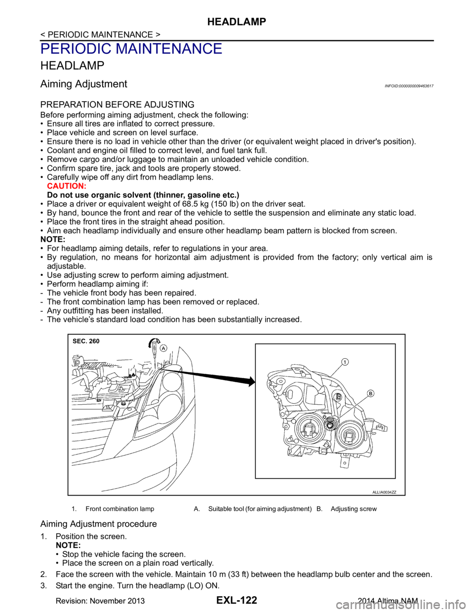
Aiming Adjustment procedure
1. Position the screen.
NOTE:
• Stop the vehicle facing the screen.
• Place the screen on a plain road vertically.
2. Face the screen with the vehicle. Maintain 10 m (33 ft) between the headlamp bulb center and the screen.
3. Start the engine. Turn the headlamp (LO) ON.
1. Front combination lamp A. Suitable tool (for aiming adjustment) B. Adjusting screw
ALLIA0034ZZ
Revision: November 20132014 Altima NAMRevision: November 20132014 Altima NAM
Page 2390 of 4801
EXL-124
< PERIODIC MAINTENANCE >
FRONT FOG LAMP
FRONT FOG LAMP
Aiming AdjustmentINFOID:0000000009463618
PREPARATION BEFORE ADJUSTING
The fog lamp is a semi-sealed beam type which uses a replaceable halogen bulb. Before performing aiming
adjustment procedure, check the following:
• Ensure all tires are inflated to correct pressure.
• Place vehicle and screen on level surface.
• Ensure there is no load in vehicle other than the driver (or equivalent weight placed in driver's position).
• Coolant and engine oil filled to correct level, and fuel tank full.
• Remove cargo and/or luggage to maintain an unloaded vehicle condition.
• Confirm spare tire, jack and tools are properly stowed.
• Carefully wipe off any dirt from headlamp lens. CAUTION:
Do not use organic solvent (thinner, gasoline etc.)
• Place a driver or equivalent weight of 68.5 kg (150 lb) on the driver seat.
• By hand, bounce the front and rear of the vehicle to settle the suspension and eliminate any static load.
• Place the front tires in the straight ahead position.
• Aim each headlamp individually and ensure other headlamp beam pattern is blocked from screen.
NOTE:
• For headlamp aiming details, refer to regulations in your area.
• By regulation, no means for horizontal aim adjustment is provided from the factory; only vertical aim is
adjustable.
• Use adjusting screw to perform aiming adjustment.
• Perform headlamp aiming if:
- The vehicle front body has been repaired.
- The front combination lamp has been removed or replaced.
- Any outfitting has been installed.
- The vehicle’s standard load condition has been substantially increased.
Aiming Adjustment Procedure
1. Place the screen. NOTE:
• Stop the vehicle facing the wall.
• Place the board on a plain road vertically.
2. Face the vehicle with the screen. Maintain 7.62 m (25.0 ft) between the front fog lamp center and the
screen.
3. Start the engine. Turn the front fog lamp ON. NOTE:
Shut off the headlamp light with the board to prevent from illuminating the adjustment screen.
CAUTION:
Do not cover the lens surface with a tape etc. The lens is made of resin.
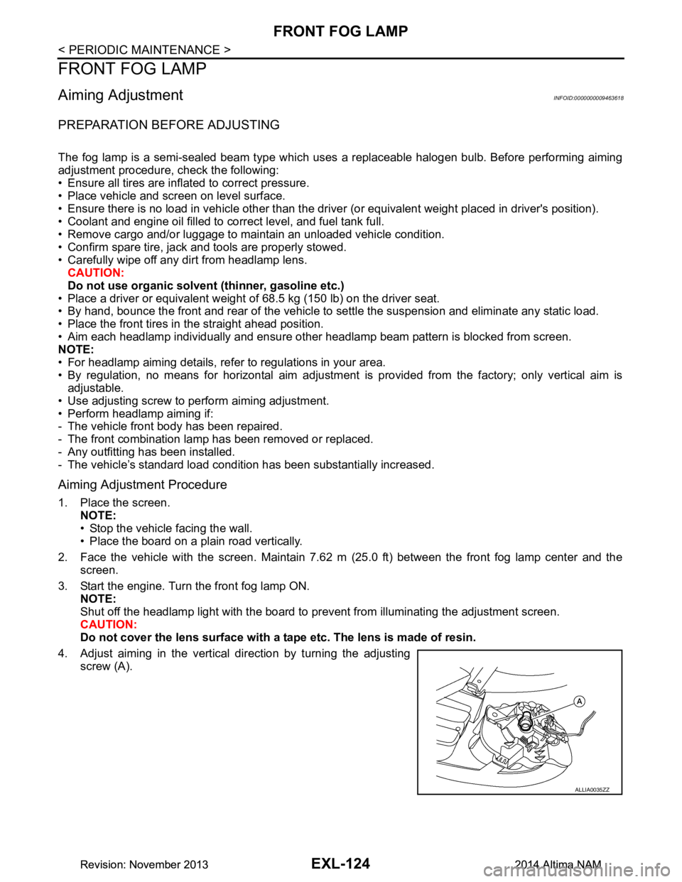
4. Adjust aiming in the vertical direction by turning the adjusting screw (A).
ALLIA0035ZZ
Revision: November 20132014 Altima NAMRevision: November 20132014 Altima NAM
Page 2503 of 4801
FSU-2
< PRECAUTION >
PRECAUTIONS
PRECAUTION
PRECAUTIONS
Precaution for Supplemental Restraint System (SRS) "AIR BAG" and "SEAT BELT
PRE-TENSIONER"
INFOID:0000000009951705
The Supplemental Restraint System such as “A IR BAG” and “SEAT BELT PRE-TENSIONER”, used along
with a front seat belt, helps to reduce the risk or severi ty of injury to the driver and front passenger for certain
types of collision. Information necessary to service the system safely is included in the SR and SB section of
this Service Manual.
WARNING:
• To avoid rendering the SRS inopera tive, which could increase the risk of personal injury or death in
the event of a collision which would result in air bag inflation, all maintenance must be performed by
an authorized NISS AN/INFINITI dealer.
• Improper maintenance, including in correct removal and installation of the SRS, can lead to personal
injury caused by unintent ional activation of the system. For re moval of Spiral Cable and Air Bag
Module, see the SR section.
• Do not use electrical test equipmen t on any circuit related to the SRS unless instructed to in this
Service Manual. SRS wiring harn esses can be identified by yellow and/or orange harnesses or har-
ness connectors.
PRECAUTIONS WHEN USING POWER TOOLS (AIR OR ELECTRIC) AND HAMMERS
WARNING:
• When working near the Airbag Diagnosis Sensor Unit or other Airbag System sensors with the Igni-
tion ON or engine running, DO NOT use air or electri c power tools or strike near the sensor(s) with a
hammer. Heavy vibration could activate the sensor( s) and deploy the air bag(s), possibly causing
serious injury.
• When using air or electric power tools or hammers , always switch the Ignition OFF, disconnect the
battery and wait at least three minutes before performing any service.
General PrecautionsINFOID:0000000009460620
• When installing rubber bushings, the final tightening mu st be carried out under unladen conditions with tires
on ground. Oil might shorten the life of rubber bushings. Be sure to wipe off any spilled oil.
- Unladen conditions mean that fuel, engine coolant and lubricant are full. Spare tire, jack, hand tools and mats are in designated positions.
• After servicing suspension parts, be sure to check wheel alignment.
• Self-lock nuts are not reusable. Always use new ones when installing. Since new self-lock nuts are pre-oiled,
tighten as they are.
Precaution for Procedure without Cowl Top CoverINFOID:0000000009460621
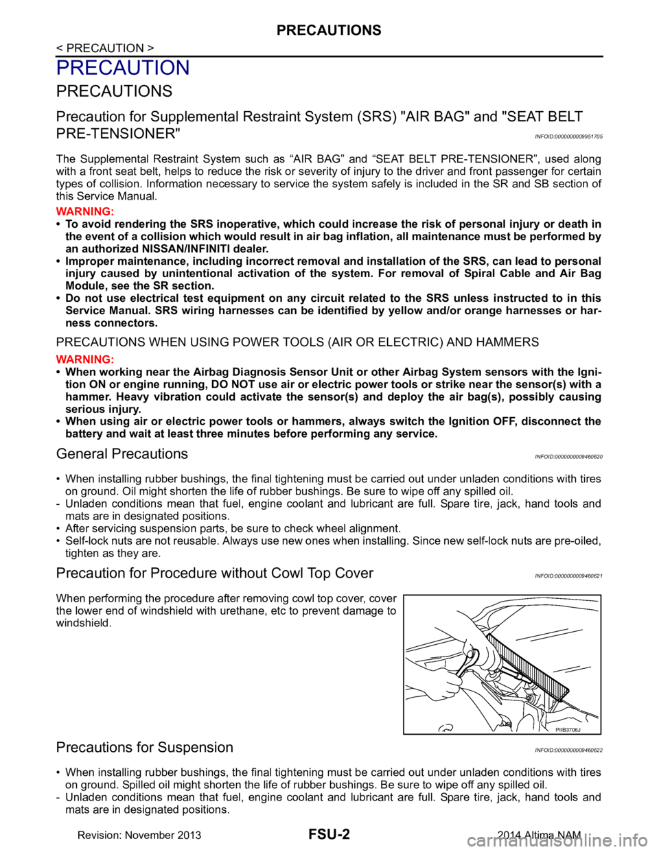
When performing the procedure after removing cowl top cover, cover
the lower end of windshield with urethane, etc to prevent damage to
windshield.
Precautions for SuspensionINFOID:0000000009460622
• When installing rubber bushings, the final tightening mu st be carried out under unladen conditions with tires
on ground. Spilled oil might shorten the life of rubber bushings. Be sure to wipe off any spilled oil.
- Unladen conditions mean that fuel, engine coolant and lubricant are full. Spare tire, jack, hand tools and mats are in designated positions.
PIIB3706J
Revision: November 20132014 Altima NAM