Crankshaft NISSAN TEANA 2014 User Guide
[x] Cancel search | Manufacturer: NISSAN, Model Year: 2014, Model line: TEANA, Model: NISSAN TEANA 2014Pages: 4801, PDF Size: 51.2 MB
Page 1047 of 4801
SYSTEMEC-47
< SYSTEM DESCRIPTION > [QR25DE]
C
D E
F
G H
I
J
K L
M A
EC
NP
O
by input signals (for engine speed and intake air) from t
he crankshaft position sensor (POS), camshaft position
sensor (PHASE) and the mass air flow sensor.
VARIOUS FUEL INJECTION INCREASE/DECREASE COMPENSATION
In addition, the amount of fuel injected is compens ated to improve engine performance under various operat-
ing conditions as listed below.
• When starting the engine
• During acceleration
• Hot-engine operation
• When selector lever is changed from N to D
• High-load, high-speed operation
• During deceleration
• During high engine speed operation
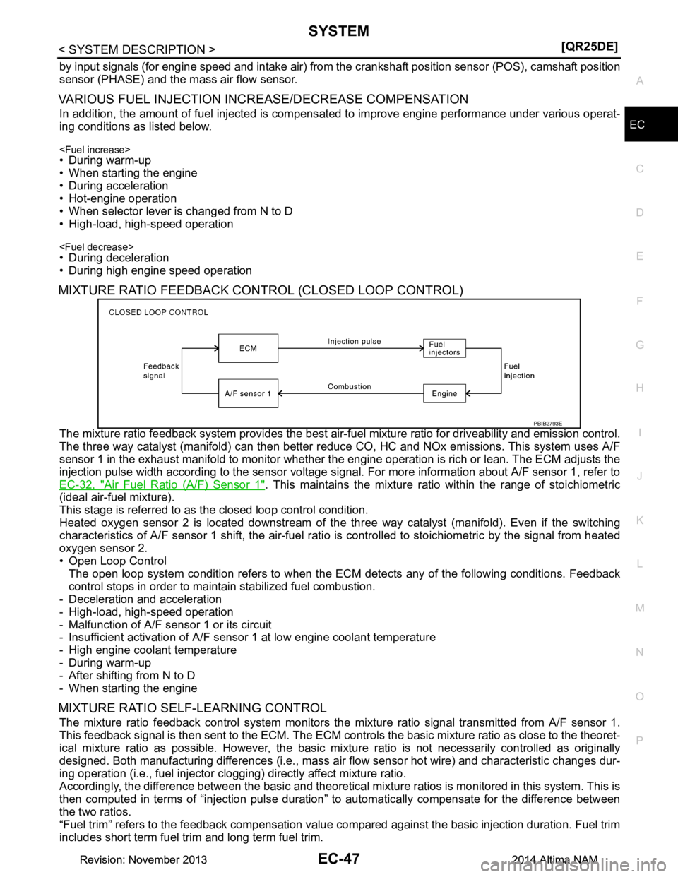
MIXTURE RATIO FEEDBACK CONTROL (CLOSED LOOP CONTROL)
The mixture ratio feedback system prov ides the best air-fuel mixture ratio for driveability and emission control.
The three way catalyst (manifold) can then better r educe CO, HC and NOx emissions. This system uses A/F
sensor 1 in the exhaust manifold to monitor whether t he engine operation is rich or lean. The ECM adjusts the
injection pulse width according to the sensor voltage si gnal. For more information about A/F sensor 1, refer to
EC-32, "Air Fuel Ratio (A/F) Sensor 1"
. This maintains the mixture rati o within the range of stoichiometric
(ideal air-fuel mixture).
This stage is referred to as the closed loop control condition.
Heated oxygen sensor 2 is located downstream of the th ree way catalyst (manifold). Even if the switching
characteristics of A/F sensor 1 shift, the air-fuel rati o is controlled to stoichiometric by the signal from heated
oxygen sensor 2.
• Open Loop Control
The open loop system condition refers to when the EC M detects any of the following conditions. Feedback
control stops in order to maintain stabilized fuel combustion.
- Deceleration and acceleration
- High-load, high-speed operation
- Malfunction of A/F sensor 1 or its circuit
- Insufficient activation of A/F sensor 1 at low engine coolant temperature
- High engine coolant temperature
- During warm-up
- After shifting from N to D
- When starting the engine
MIXTURE RATIO SELF-LEARNING CONTROL
The mixture ratio feedback control system monitors the mixture ratio signal transmitted from A/F sensor 1.
This feedback signal is then sent to the ECM. The ECM cont rols the basic mixture ratio as close to the theoret-
ical mixture ratio as possible. However, the basic mi xture ratio is not necessarily controlled as originally
designed. Both manufacturing differences (i.e., mass air flow sensor hot wire) and characteristic changes dur-
ing operation (i.e., fuel injector clogging) directly affect mixture ratio.
Accordingly, the difference between the basic and theoretical mixture ratios is monitored in this system. This is
then computed in terms of “injection pulse duration” to automatically compensate for the difference between
the two ratios.
“Fuel trim” refers to the feedback compensation value co mpared against the basic injection duration. Fuel trim
includes short term fuel trim and long term fuel trim.
PBIB2793E
Revision: November 20132014 Altima NAMRevision: November 20132014 Altima NAM
Page 1049 of 4801
SYSTEMEC-49
< SYSTEM DESCRIPTION > [QR25DE]
C
D E
F
G H
I
J
K L
M A
EC
NP
O
The ECM receives information such as the injecti
on pulse width and camshaft position sensor (PHASE) sig-
nal. Computing this information, ignition si gnals are transmitted to the power transistor.
During the following conditions, the ignition timing is revi sed by the ECM according to the other data stored in
the ECM.
• At starting
• During warm-up
•At idle
• At low battery voltage
• During acceleration
The knock sensor retard system is designed only for emergencies. The basic ignition timing is programmed
within the anti-knocking zone, if recommended fuel is used under dry conditions. The retard system does not
operate under normal driving conditions. If engine knocking occurs, the knock sensor monitors the condition.
The signal is transmitted to the ECM. The ECM retards the ignition timing to eliminate the knocking condition.
INTAKE VALVE TIMING CONTROL
INTAKE VALVE TIMING CONTROL : System DescriptionINFOID:0000000009462096
INTAKE VALVE TIMING CONTROL
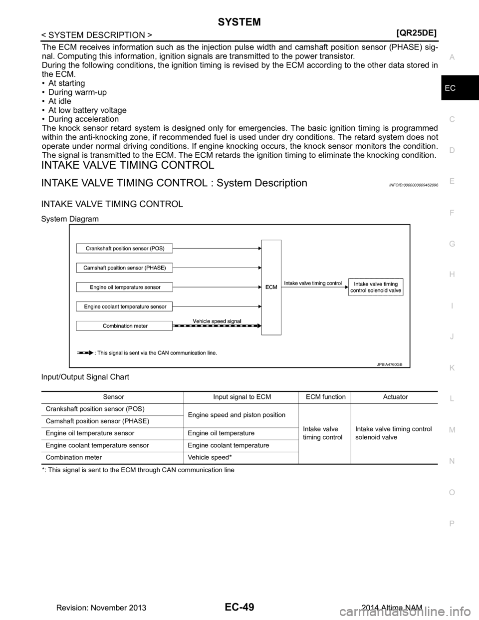
System Diagram
Input/Output Signal Chart
*: This signal is sent to the ECM through CAN communication line
JPBIA4760GB
Sensor Input signal to ECM ECM function Actuator
Crankshaft position sensor (POS) Engine speed and piston position
Intake valve
timing control Intake valve timing control
solenoid valve
Camshaft position sensor (PHASE)
Engine oil temperature sensor Engine oil temperature
Engine coolant temperature sensor Engine coolant temperature
Combination meter Vehicle speed*
Revision: November 20132014 Altima NAMRevision: November 20132014 Altima NAM
Page 1050 of 4801
EC-50
< SYSTEM DESCRIPTION >[QR25DE]
SYSTEM
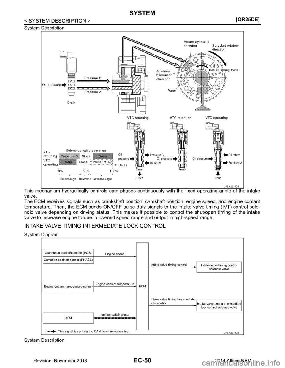
System Description
This mechanism hydraulically controls cam phases c
ontinuously with the fixed operating angle of the intake
valve.
The ECM receives signals such as crankshaft posit ion, camshaft position, engine speed, and engine coolant
temperature. Then, the ECM sends ON/OFF pulse duty si gnals to the intake valve timing (IVT) control sole-
noid valve depending on driving status. This makes it po ssible to control the shut/open timing of the intake
valve to increase engine torque in low/mid speed range and output in high-speed range.
INTAKE VALVE TIMING INTERMEDIATE LOCK CONTROL
System Diagram
System Description
JPBIA6316GB
JPBIA5973GB
Revision: November 20132014 Altima NAMRevision: November 20132014 Altima NAM
Page 1052 of 4801
EC-52
< SYSTEM DESCRIPTION >[QR25DE]
SYSTEM
When starting the engine by cold start, ECM judges the
locked/unlocked state when ignition switch is turned
ON. When judged as locked state (fixed at the intermedi ate phase), the intake valve timing intermediate lock
control solenoid valve is activated. Since oil pre ssure does not act on the lock key even when the engine is
started, the cam phase is fixed at the intermediate phas e and the intake valve timing control is not performed.
When the engine stops without locking the cam phase at the intermediate phase due to an engine stall and the
state is not judged as locked, the intake valve timing intermediate lock control solenoid valve and the intake
valve timing control solenoid valve are activated and the cam phase shifts to the advanced position to be
locked at the intermediate phase. Even when not locked in the intermediate lock phase due to no oil pressure
or low oil pressure, a ratchet structure of the camshaft sprocket (INT) rotor allows the conversion to the inter-
mediate phase in stages by engine vibration.
When engine coolant temperature is more than 60 °C, the intake valve timing is controlled by deactivating the
intake valve timing intermediate lock control so lenoid valve and releasing the intermediate phase lock.
When the engine is started after warming up, ECM releas es the intermediate phase lock immediately after the
engine start and controls the intake valve timing.
EXHAUST VALVE TIMING CONTROL
EXHAUST VALVE TIMING CONT ROL : System DescriptionINFOID:0000000009462097
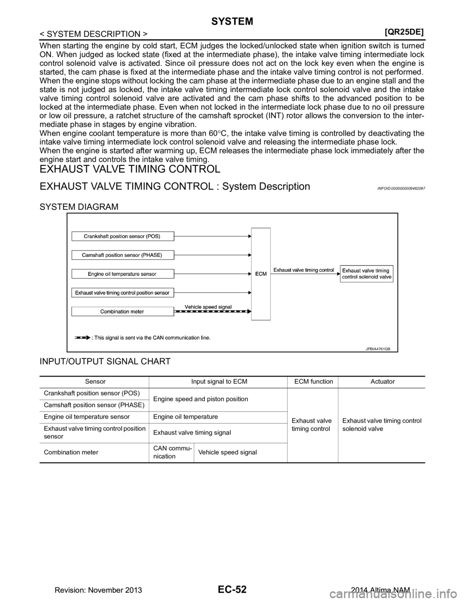
SYSTEM DIAGRAM
INPUT/OUTPUT SIGNAL CHART
JPBIA4761GB
Sensor Input signal to ECM ECM function Actuator
Crankshaft position sensor (POS) Engine speed and piston position
Exhaust valve
timing control Exhaust valve timing control
solenoid valve
Camshaft position sensor (PHASE)
Engine oil temperature sensor Engine oil temperature
Exhaust valve timing control position
sensor Exhaust valve timing signal
Combination meter CAN commu-
nication Vehicle speed signal
Revision: November 20132014 Altima NAMRevision: November 20132014 Altima NAM
Page 1053 of 4801
SYSTEMEC-53
< SYSTEM DESCRIPTION > [QR25DE]
C
D E
F
G H
I
J
K L
M A
EC
NP
O
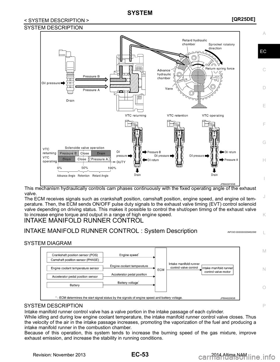
SYSTEM DESCRIPTION
This mechanism hydraulically controls cam phases c
ontinuously with the fixed operating angle of the exhaust
valve.
The ECM receives signals such as crankshaft position, camshaft position, engine speed, and engine oil tem-
perature. Then, the ECM sends ON/OFF pulse duty signal s to the exhaust valve timing (EVT) control solenoid
valve depending on driving status. This makes it possible to control the shut/open timing of the exhaust valve
to increase engine torque and output in a range of high engine speed.
INTAKE MANIFOLD RUNNER CONTROL
INTAKE MANIFOLD RUNNER CONTROL : System DescriptionINFOID:0000000009462098
SYSTEM DIAGRAM
SYSTEM DESCRIPTION
Intake manifold runner control valve has a valve portion in the intake passage of each cylinder.
While idling and during low engine coolant temperature, t he intake manifold runner control valve closes. Thus
the velocity of the air in the intake passage increases , promoting the vaporization of the fuel and producing a
intake manifold runner in the combustion chamber.
Because of this operation, this system tends to in crease the burning speed of the gas mixture, improve
exhaust emission, and increase the stability in running conditions.
JPBIA5972GB
JPBIA6226GB
Revision: November 20132014 Altima NAMRevision: November 20132014 Altima NAM
Page 1055 of 4801
SYSTEMEC-55
< SYSTEM DESCRIPTION > [QR25DE]
C
D E
F
G H
I
J
K L
M A
EC
NP
O
Intake Manifold Tuning Valve Operating Condition
ECM opens the intake manifold tuning valve when all of the following conditions are satisfied.
• Engine speed: 5,000 rpm or more
• Engine coolant temperature: -30 °C (-22 °F) or more
• Battery voltage: 16 V or less
ENGINE PROTECTION CONTROL AT LOW ENGINE OIL PRESSURE
ENGINE PROTECTION CONTROL AT LOW ENGINE OIL PRESSURE : System De-
scription
INFOID:0000000009462100
SYSTEM DIAGRAM
INPUT/OUTPUT SIGNAL CHART
SYSTEM DESCRIPTION
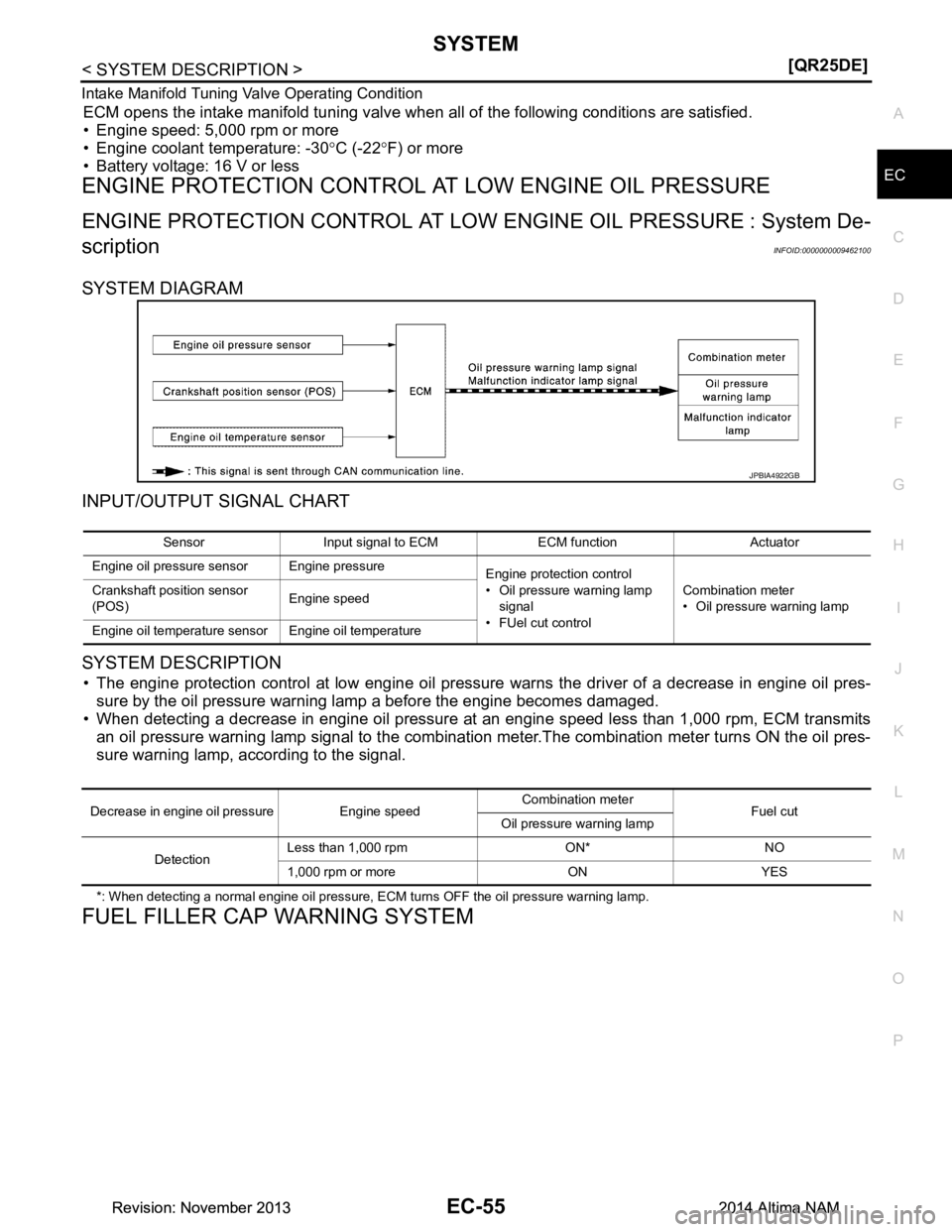
• The engine protection control at low engine oil pressure warns the driver of a decrease in engine oil pres-
sure by the oil pressure warning lamp a before the engine becomes damaged.
• When detecting a decrease in engine oil pressure at an engine speed less than 1,000 rpm, ECM transmits an oil pressure warning lamp signal to the combination meter.The combination meter turns ON the oil pres-
sure warning lamp, according to the signal.
*: When detecting a normal engine oil pressure, ECM turns OFF the oil pressure warning lamp.
FUEL FILLER CAP WARNING SYSTEM
JPBIA4922GB
Sensor Input signal to ECM ECM function Actuator
Engine oil pressure sensor Engine pressure Engine protection control
• Oil pressure warning lamp
signal
•FUel cut control Combination meter
• Oil pressure warning lamp
Crankshaft position sensor
(POS) Engine speed
Engine oil temperature sensor Engine oil temperature
Decrease in engine oil pressure Engine speed Combination meter
Fuel cut
Oil pressure warning lamp
Detection Less than 1,000 rpm ON* NO
1,000 rpm or more ON YES
Revision: November 20132014 Altima NAMRevision: November 20132014 Altima NAM
Page 1062 of 4801
EC-62
< SYSTEM DESCRIPTION >[QR25DE]
SYSTEM
EVAPORATIVE EMISSION SYSTEM : System Description
INFOID:0000000009462106
SYSTEM DIAGRAM
INPUT/OUTPUT SIGNAL CHART
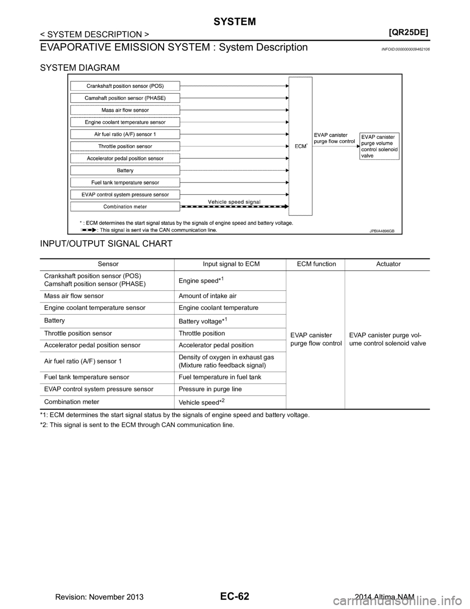
*1: ECM determines the start signal status by the signals of engine speed and battery voltage.
*2: This signal is sent to the ECM through CAN communication line.
JPBIA4896GB
Sensor Input signal to ECM ECM function Actuator
Crankshaft position sensor (POS)
Camshaft position sensor (PHASE) Engine speed*
1
EVAP canister
purge flow control EVAP canister purge vol-
ume control solenoid valve
Mass air flow sensor Amount of intake air
Engine coolant temperature sensor Engine coolant temperature
Battery Battery voltage*
1
Throttle position sensor Throttle position
Accelerator pedal position sensor Accelerator pedal position
Air fuel ratio (A/F) sensor 1 Density of oxygen in exhaust gas
(Mixture ratio fe edback signal)
Fuel tank temperature sensor Fuel temperature in fuel tank
EVAP control system pressure sensor Pressure in purge line
Combination meter Vehicle speed*
2
Revision: November 20132014 Altima NAMRevision: November 20132014 Altima NAM
Page 1079 of 4801
DIAGNOSIS SYSTEM (ECM)EC-79
< SYSTEM DESCRIPTION > [QR25DE]
C
D E
F
G H
I
J
K L
M A
EC
NP
OMonitored item Unit Monitor Item
Selection
Description Remarks
ECU
IN-
PUT
SIG-
NALS MAIN
SIG-NAL
S
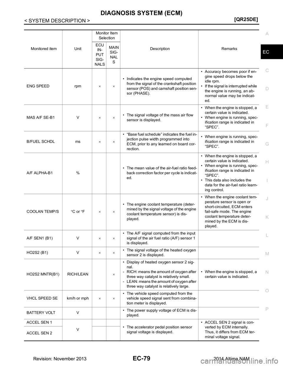
ENG SPEED rpm ×ו Indicates the engine speed computed
from the signal of the crankshaft position
sensor (POS) and camshaft position sen-
sor (PHASE). • Accuracy becomes poor if en-
gine speed drops below the
idle rpm.
• If the signal is interrupted while
the engine is running, an ab-
normal value may be indicat-
ed.
MAS A/F SE-B1 V ×ו The signal voltage of the mass air flow
sensor is displayed. • When the engine is stopped, a
certain value is indicated.
• When engine is running, spec- ification range is indicated in
“SPEC”.
B/FUEL SCHDL ms ×ו “Base fuel schedule” indicates the fuel in-
jection pulse width programmed into
ECM, prior to any learned on board cor-
rection. • When engine is running, spec-
ification range is indicated in
“SPEC”.
A/F ALPHA-B1 % • The mean value of the air-fuel ratio feed-
back correction factor per cycle is indicat-
ed. • When the engine is stopped, a
certain value is indicated.
• When engine is running, spec-
ification range is indicated in
“SPEC”.
• This data also includes the
data for the air-fuel ratio learn-
ing control.
COOLAN TEMP/S °C or °F ×× • The engine coolant temperature (deter-
mined by the signal voltage of the engine
coolant temperature sensor) is dis-
played. • When the engine coolant tem-
perature sensor is open or
short-circuited, ECM enters
fail-safe mode. The engine
coolant temperature deter-
mined by the ECM is dis-
played.
A/F SEN1 (B1) V ×ו The A/F signal computed from the input
signal of the air fuel ratio (A/F) sensor 1
is displayed.
HO2S2 (B1) V ×ו The signal voltage of the heated oxygen
sensor 2 is displayed.
HO2S2 MNTR(B1) RICH/LEAN ו Display of heated oxygen sensor 2 sig-
nal.
- RICH: means the amount of oxygen after
three way catalyst is relatively small.
- LEAN: means the amount of oxygen after three way catalyst is relatively large. • When the engine is stopped, a
certain value is indicated.
VHCL SPEED SE km/h or mph ×ו The vehicle speed computed from the
vehicle speed signal sent from combina-
tion meter is displayed.
BATTERY VOLT V • The power supply voltage of ECM is dis-
played.
ACCEL SEN 1
V• The accelerator pedal position sensor
signal voltage is displayed. • ACCEL SEN 2 signal is con-
verted by ECM internally.
Thus, it differs from ECM ter-
minal voltage signal.
ACCEL SEN 2
Revision: November 20132014 Altima NAMRevision: November 20132014 Altima NAM
Page 1098 of 4801
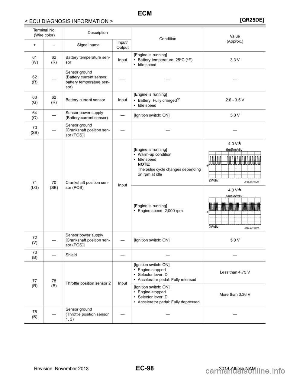
EC-98
< ECU DIAGNOSIS INFORMATION >[QR25DE]
ECM
61
(W) 62
(R) Battery temperature sen-
sor Input[Engine is running]
• Battery temperature: 25 °C ( °F)
• Idle speed 3.3 V
62
(R) —Sensor ground
(Battery curre nt sensor,
battery temperature sen-
sor) —— —
63
(G) 62
(R) Battery current sensor Input [Engine is running]
• Battery: Fully charged
*2
• Idle speed 2.6 - 3.5 V
64
(O) —Sensor power supply
(Battery curre nt sensor) — [Ignition switch: ON] 5.0 V
70
(SB) —Sensor ground
[Crankshaft position sen-
sor (POS)] —— —
71
(LG) 70
(SB) Crankshaft position sen-
sor (POS) Input[Engine is running]
• Warm-up condition
• Idle speed NOTE:
The pulse cycle changes depending
on rpm at idle 4.0 V
[Engine is running]
• Engine speed: 2,000 rpm 4.0 V
72
(V) —Sensor power supply
[Crankshaft position sen-
sor (POS)] — [Ignition switch: ON] 5.0 V
73
(B) —Shield — — —
77
(R) 78
(B) Throttle position sensor 2 Input [Ignition switch: ON]
• Engine stopped
• Selector lever: D
• Accelerator pedal: Fully released Less than 4.75 V
[Ignition switch: ON]
• Engine stopped
• Selector lever: D
• Accelerator pedal: Fully depressed More than 0.36 V
78
(B) —Sensor ground
(Throttle position sensor
1, 2) —— —
Te r m i n a l N o .
(Wire color) Description
ConditionVa l u e
(Approx.)
+ − Signal name Input/
Output
JPBIA4728ZZ
JPBIA4729ZZ
Revision: November 20132014 Altima NAMRevision: November 20132014 Altima NAM
Page 1104 of 4801
EC-104
< ECU DIAGNOSIS INFORMATION >[QR25DE]
ECM
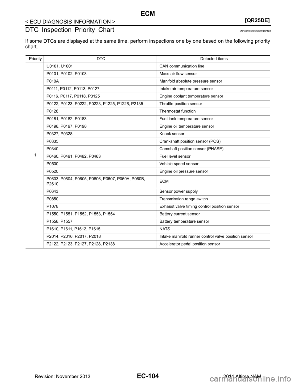
DTC Inspection Priority Chart
INFOID:0000000009462123
If some DTCs are displayed at the same time, perfo rm inspections one by one based on the following priority
chart.
Priority DTC Detected items
1 U0101, U1001 CAN communication line
P0101, P0102, P0103 Mass air flow sensor
P010A Manifold absolute pressure sensor
P0111, P0112, P0113, P0127 Intake air temperature sensor
P0116, P0117, P0118, P0125 Engine coolant temperature sensor
P0122, P0123, P0222, P0223, P1225, P1226, P2135 Throttle position sensor
P0128 Thermostat function
P0181, P0182, P0183 Fuel tank temperature sensor
P0196, P0197, P0198 Engine oil temperature sensor
P0327, P0328 Knock sensor
P0335 Crankshaft position sensor (POS)
P0340 Camshaft position sensor (PHASE)
P0460, P0461, P0462, P0463 Fuel level sensor
P0500 Vehicle speed sensor
P0520 Engine oil pressure sensor
P0603, P0604, P0605, P0606, P0607, P060A, P060B,
P2610 ECM
P0643 Sensor power supply
P0850 Transmission range switch
P1078 Exhaust valve timing control position sensor
P1550, P1551, P1552, P1553, P1554 Battery current sensor
P1556, P1557 Battery temperature sensor
P1610, P1611, P1612, P1615 NATS
P2014, P2016, P2017, P2018 Intake manifold runner control valve position sensor
P2122, P2123, P2127, P2128, P2138 Accelerator pedal position sensor
Revision: November 20132014 Altima NAMRevision: November 20132014 Altima NAM