weight NISSAN TEANA 2014 Service Manual
[x] Cancel search | Manufacturer: NISSAN, Model Year: 2014, Model line: TEANA, Model: NISSAN TEANA 2014Pages: 4801, PDF Size: 51.2 MB
Page 156 of 4801
![NISSAN TEANA 2014 Service Manual
BRC-10
< SYSTEM DESCRIPTION >[VDC/TCS/ABS]
COMPONENT PARTS
Suction Valve 1, Suction Valve 2
Supplies the brake fluid from master cylinder to t
he pump, when VDC function and TCS function are activate NISSAN TEANA 2014 Service Manual
BRC-10
< SYSTEM DESCRIPTION >[VDC/TCS/ABS]
COMPONENT PARTS
Suction Valve 1, Suction Valve 2
Supplies the brake fluid from master cylinder to t
he pump, when VDC function and TCS function are activate](/img/5/57390/w960_57390-155.png)
BRC-10
< SYSTEM DESCRIPTION >[VDC/TCS/ABS]
COMPONENT PARTS
Suction Valve 1, Suction Valve 2
Supplies the brake fluid from master cylinder to t
he pump, when VDC function and TCS function are activated.
Return Check Valve
Returns the brake fluid from brake caliper and wheel cy linder to master cylinder by bypassing orifice of each
valve when brake is released.
Reservoir
Temporarily reserves the brake fluid drained from brake caliper, so that pressure efficiently decreases when
decreasing pressure of brake caliper and wheel cylinder.
Yaw rate/side/decel G sensor
Calculates the following information that affects the vehicle, and transmits a signal to ABS actuator and elec-
tric unit (control unit) via communication lines.
• Vehicle rotation angular velocity (yaw rate signal)
• Vehicle lateral acceleration (side G signal) and longitudinal acceleration (decel G signal)
Pressure Sensor
Detects the brake fluid pressure and transmits signal to ABS actuator and electric unit (control unit).
Wheel Sensor and Sensor RotorINFOID:0000000009463744
NOTE:
• Wheel sensor of front wheel is installed on steering knuckle.
• Sensor rotor of front wheel is integrated in wheel hub assembly.
• Wheel sensor of rear wheel is installed on back plate of rear brake.
• Sensor rotor of rear wheel is installed on rear brake drum.
• Never measure resistance and voltage value using a tester because sensor is active sensor.
• Downsize and weight reduction is aimed. IC for detection portion and magnet for sensor rotor are adopted.
• Power supply is supplied to detection portion so that magnetic field line is read. Magnetic field that is detected is converted to current
signal.
• When sensor rotor rotates, magnetic field changes. Magnetic field change is converted to current signals (rectangular wave) and is
transmitted to ABS actuator and el ectric unit (control unit). Change
of magnetic field is proportional to wheel speed.
Stop Lamp SwitchINFOID:0000000009463745
Detects the operation status of brake pedal and transmits converted electric signal to ABS actuator and elec-
tric unit (control unit).
Steering Angle SensorINFOID:0000000009463746
Detects the following information and transmits steering angl e signal to ABS actuator and electric unit (control
unit) via CAN communication.
• Steering wheel rotation amount
• Steering wheel rotation angular velocity
• Steering wheel rotation direction
Brake Fluid Level SwitchINFOID:0000000009463747
Detects the brake fluid level in reservoir tank and transmi ts converted electric signal from combination meter to
ABS actuator and electric unit (control unit) via CAN communication.
Vacuum SensorINFOID:0000000009463748
Detects the vacuum in brake booster and transmits conver ted electric signal to ABS actuator and electric unit
(control unit).
JPFIC0131GB
Revision: November 20132014 Altima NAMRevision: November 20132014 Altima NAM
Page 174 of 4801
![NISSAN TEANA 2014 Service Manual
BRC-28
< SYSTEM DESCRIPTION >[VDC/TCS/ABS]
SYSTEM
Major signal transmission between each unit via communication lines is shown in the following table.
VDC/TCS/ABS : EBD FunctionINFOID:000000000946375 NISSAN TEANA 2014 Service Manual
BRC-28
< SYSTEM DESCRIPTION >[VDC/TCS/ABS]
SYSTEM
Major signal transmission between each unit via communication lines is shown in the following table.
VDC/TCS/ABS : EBD FunctionINFOID:000000000946375](/img/5/57390/w960_57390-173.png)
BRC-28
< SYSTEM DESCRIPTION >[VDC/TCS/ABS]
SYSTEM
Major signal transmission between each unit via communication lines is shown in the following table.
VDC/TCS/ABS : EBD FunctionINFOID:0000000009463756
SYSTEM DIAGRAM
• By preventing rear wheel slip increase through rear wheel
brake force (brake fluid pressure) control that is
electronically controlled when slight skip on front and r ear wheels are detected during braking, stability dur-
ing braking is improved.
• EBD function is expanded and developed from conventi onal ABS function and corrects rear wheel brake
force to appropriate level by electronic control according to load weight (number of passengers).
Component Signal description
Combination meter Receives the following signals from ABS actuator
and electric unit (control unit) via CAN com-
munication.
• VDC warning lamp signal
• ABS warning lamp signal
ALFIA0297GB
JPFIC0142GB
Revision: November 20132014 Altima NAMRevision: November 20132014 Altima NAM
Page 285 of 4801
PRECAUTIONS IN REPAIRING HIGH STRENGTH STEELBRM-7
< PRECAUTION >
C
D E
F
G H
I
J
L
M A
B
BRM
N
O P
PRECAUTIONS IN REPAIRIN G HIGH STRENGTH STEEL
High Strength Steel (HSS)INFOID:0000000009464964
High strength steel is used for body panel s in order to reduce vehicle weight.
Accordingly, precautions in repairing automotive bodies made of high strength steel are described below:
SP130 is the most commonly used HSS.
Read the following precautions when repairing HSS.
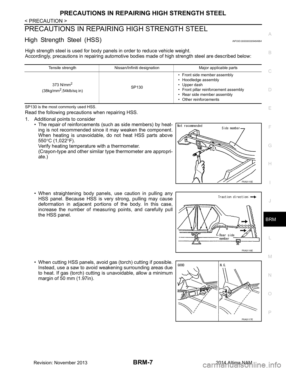
1. Additional points to consider • The repair of reinforcements (such as side members) by heat-
ing is not recommended since it may weaken the component.
When heating is unavoidable, do not heat HSS parts above
550 °C (1,022 °F).
Verify heating temperature with a thermometer.
(Crayon-type and other similar type thermometer are appropri-
ate.)
• When straightening body panels, use caution in pulling any HSS panel. Because HSS is very strong, pulling may cause
deformation in adjacent portions of the body. In this case,
increase the number of measuring points, and carefully pull
the HSS panel.
• When cutting HSS panels, avoid gas (torch) cutting if possible. Instead, use a saw to avoid weakening surrounding areas due
to heat. If gas (torch) cutting is unavoidable, allow a minimum
margin of 50 mm (1.97in).
Tensile strength Nissan/Infiniti designation Major applicable parts
373 N/mm
2
(38kg/mm2,54klb/sq in) SP130• Front side member assembly
• Hoodledge assembly
• Upper dash
• Front pillar reinforcement assembly
• Rear side member assembly
• Other reinforcements
PIIA0115E
PIIA0116E
PIIA0117E
Revision: November 20132014 Altima NAM
Page 938 of 4801
DLK-170
< REMOVAL AND INSTALLATION >
HOOD
REMOVAL AND INSTALLATION
HOOD
HOOD ASSEMBLY
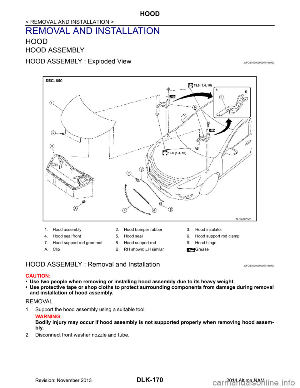
HOOD ASSEMBLY : Exploded ViewINFOID:0000000009461922
HOOD ASSEMBLY : Removal and InstallationINFOID:0000000009461923
CAUTION:
• Use two people when removing or instal ling hood assembly due to its heavy weight.
• Use protective tape or shop cloths to protect surrounding components from damage during removal
and installation of hood assembly.
REMOVAL
1. Support the hood assembly using a suitable tool.
WARNING:
Bodily injury may occur if hood assembly is not supported properly when removing hood assem-
bly.
2. Disconnect front washer nozzle and tube.
1. Hood assembly 2. Hood bumper rubber 3. Hood insulator
4. Hood seal front 5. Hood seal 6. Hood support rod clamp
7. Hood support rod grommet 8. Hood support rod 9. Hood hinge
A. Clip B. RH shown; LH similar Grease
ALKIA2675ZZ
Revision: November 20132014 Altima NAMRevision: November 20132014 Altima NAM
Page 942 of 4801
DLK-174
< REMOVAL AND INSTALLATION >
HOOD
4. Temporarily tighten hood lock assembly bolts.
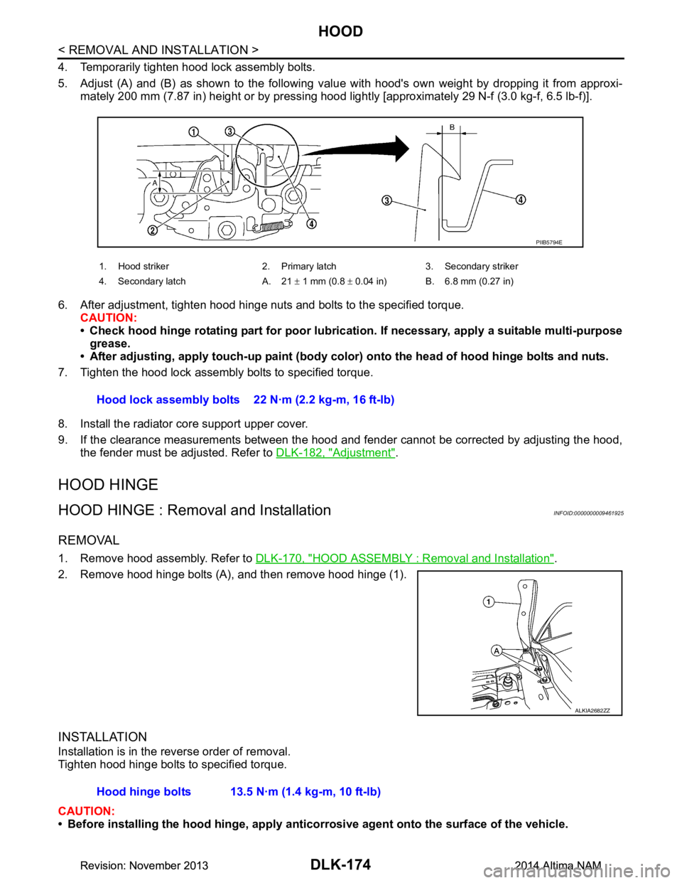
5. Adjust (A) and (B) as shown to the following val ue with hood's own weight by dropping it from approxi-
mately 200 mm (7.87 in) height or by pressing hood light ly [approximately 29 N-f (3.0 kg-f, 6.5 lb-f)].
6. After adjustment, tighten hood hinge nuts and bolts to the specified torque. CAUTION:
• Check hood hinge rotating part for poor lubrication. If necessary, apply a suitable multi-purpose
grease.
• After adjusting, apply touch-up paint (body color) onto the head of hood hinge bolts and nuts.
7. Tighten the hood lock assembly bolts to specified torque.
8. Install the radiator core support upper cover.
9. If the clearance measurements between the hood and fender cannot be corrected by adjusting the hood,
the fender must be adjusted. Refer to DLK-182, "Adjustment"
.
HOOD HINGE
HOOD HINGE : Removal and InstallationINFOID:0000000009461925
REMOVAL
1. Remove hood assembly. Refer to DLK-170, "HOOD ASSEMBLY : Removal and Installation".
2. Remove hood hinge bolts (A), and then remove hood hinge (1).
INSTALLATION
Installation is in the reverse order of removal.
Tighten hood hinge bolts to specified torque.
CAUTION:
• Before installing the hood hinge, apply anticorrosive agent onto the surface of the vehicle.
1. Hood striker 2. Primary latch 3. Secondary striker
4. Secondary latch A. 21 ± 1 mm (0.8 ± 0.04 in) B. 6.8 mm (0.27 in)
PIIB5794E
Hood lock assembly bolts 22 N·m (2.2 kg-m, 16 ft-lb)
ALKIA2682ZZ
Hood hinge bolts 13.5 N·m (1.4 kg-m, 10 ft-lb)
Revision: November 20132014 Altima NAMRevision: November 20132014 Altima NAM
Page 945 of 4801
HOOD
DLK-177
< REMOVAL AND INSTALLATION >
C
D E
F
G H
I
J
L
M A
B
DLK
N
O P
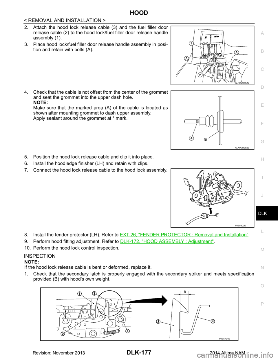
2. Attach the hood lock release cable (3) and the fuel filler door release cable (2) to the hood lock/fuel filler door release handle
assembly (1).
3. Place hood lock/fuel filler door release handle assembly in posi- tion and retain with bolts (A).
4. Check that the cable is not offset from the center of the grommet
and seat the grommet into the upper dash hole.
NOTE:
Make sure that the marked area (A) of the cable is located as
shown after mounting grommet to dash upper assembly.
Apply sealant around the grommet at * mark.
5. Position the hood lock release cable and clip it into place.
6. Install the hoodledge finisher (LH) and retain with clips.
7. Connect the hood lock release cable to the hood lock assembly.
8. Install the fender protector (LH). Refer to EXT-26, "FENDER PROTECTOR : Removal and Installation"
.
9. Perform hood fitting adjustment. Refer to DLK-172, "HOOD ASSEMBLY : Adjustment"
.
10. Perform the hood lock control inspection.
INSPECTION
NOTE:
If the hood lock release cable is bent or deformed, replace it.
1. Check that the secondary latch is properly engaged wi th the secondary striker and meets specification
provided (B) with hood's own weight.
ALKIA2665ZZ
ALKIA2139ZZ
PIIB5802E
PIIB5794E
Revision: November 20132014 Altima NAMRevision: November 20132014 Altima NAM
Page 952 of 4801
DLK-184
< REMOVAL AND INSTALLATION >
FRONT DOOR
FRONT DOOR
DOOR ASSEMBLY
DOOR ASSEMBLY : Removal and InstallationINFOID:0000000009461933
CAUTION:
• Use two people when removing or installing the front door assembly due to its heavy weight.
• When removing and installing front door assembl y, support front door with a suitable tool.
• Do not use air tools or el ectric tools for servicing.
• Before servicing, turn ignition sw itch OFF, disconnect both battery terminals and wait at least three
minutes.
NOTE:
LH side shown; RH side similar.
REMOVAL
1. Disconnect the battery negative and positive terminals and wait at least three minutes with the side air bag (satellite) sensor (if equipped).
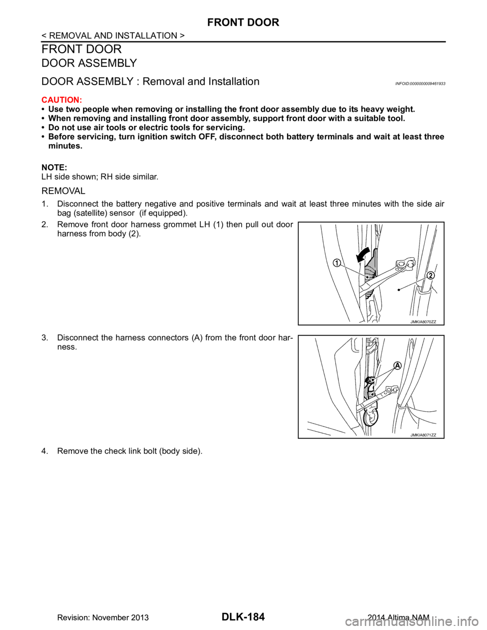
2. Remove front door harness grommet LH (1) then pull out door harness from body (2).
3. Disconnect the harness connectors (A) from the front door har- ness.
4. Remove the check link bolt (body side).
JMKIA8070ZZ
JMKIA8071ZZ
Revision: November 20132014 Altima NAMRevision: November 20132014 Altima NAM
Page 956 of 4801
DLK-188
< REMOVAL AND INSTALLATION >
FRONT DOOR
DOOR STRIKER ADJUSTMENT
Adjust front door striker so that it becomes parallel with door lock insertion direction.
DOOR STRIKER
DOOR STRIKER : Removal and InstallationINFOID:0000000009461935
REMOVAL
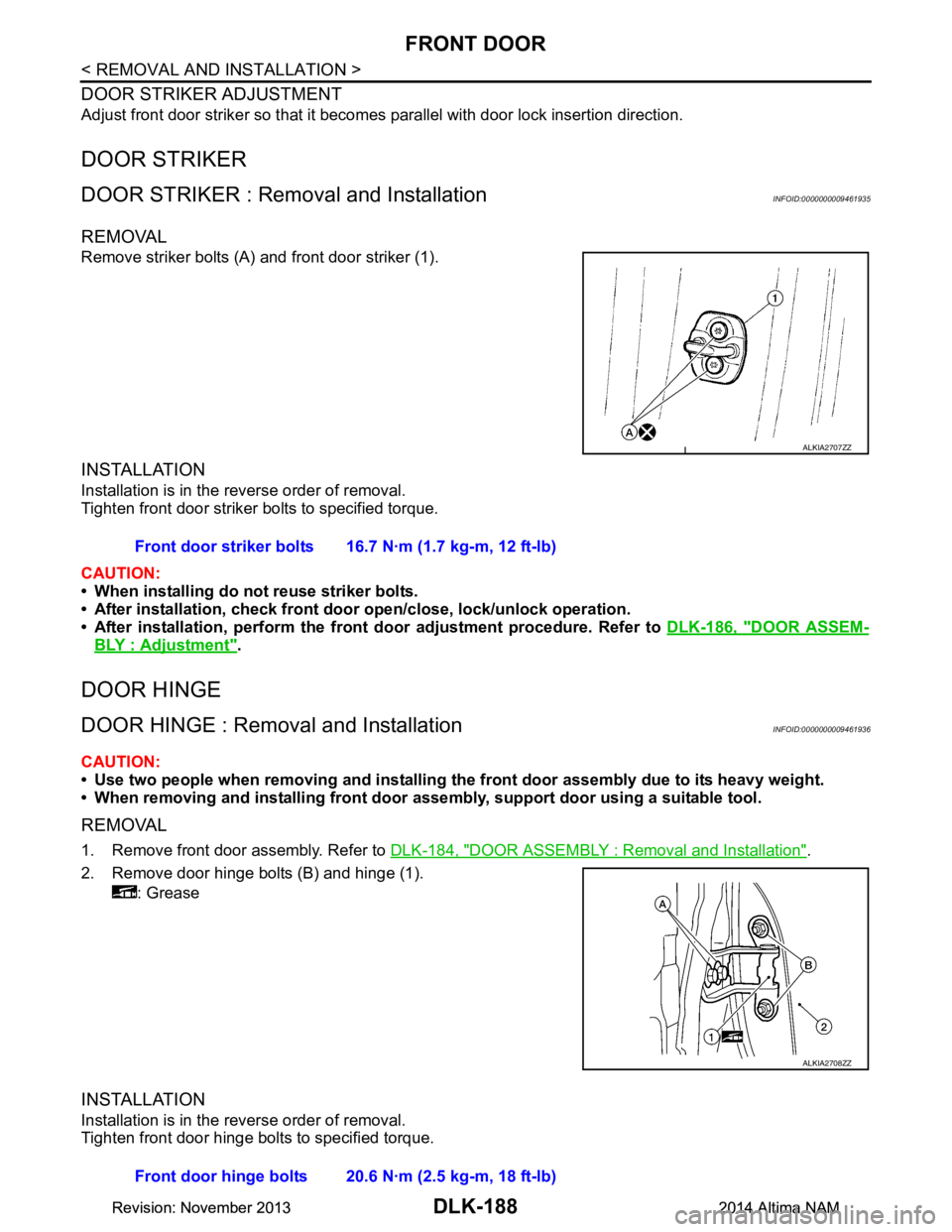
Remove striker bolts (A) and front door striker (1).
INSTALLATION
Installation is in the reverse order of removal.
Tighten front door striker bolts to specified torque.
CAUTION:
• When installing do not reuse striker bolts.
• After installation, check front doo r open/close, lock/unlock operation.
• After installation, perform the front door adjustment procedure. Refer to DLK-186, "DOOR ASSEM-
BLY : Adjustment".
DOOR HINGE
DOOR HINGE : Removal and InstallationINFOID:0000000009461936
CAUTION:
• Use two people when removing and installing the front door assembly due to its heavy weight.
• When removing and installing front door assembly, support door using a suitable tool.
REMOVAL
1. Remove front door assembly. Refer to DLK-184, "DOOR ASSEMBLY : Removal and Installation".
2. Remove door hinge bolts (B) and hinge (1). : Grease
INSTALLATION
Installation is in the reverse order of removal.
Tighten front door hinge bolts to specified torque.
ALKIA2707ZZ
Front door striker bolts 16.7 N·m (1.7 kg-m, 12 ft-lb)
ALKIA2708ZZ
Front door hinge bolts 20.6 N·m (2.5 kg-m, 18 ft-lb)
Revision: November 20132014 Altima NAMRevision: November 20132014 Altima NAM
Page 958 of 4801
DLK-190
< REMOVAL AND INSTALLATION >
REAR DOOR
REAR DOOR
DOOR ASSEMBLY
DOOR ASSEMBLY : Removal and InstallationINFOID:0000000009461938
CAUTION:
• Use two people when removing or installing the rear door assembly due to its heavy weight.
• When removing and installing rear door assembly, support rear door with a suitable tool.
REMOVAL
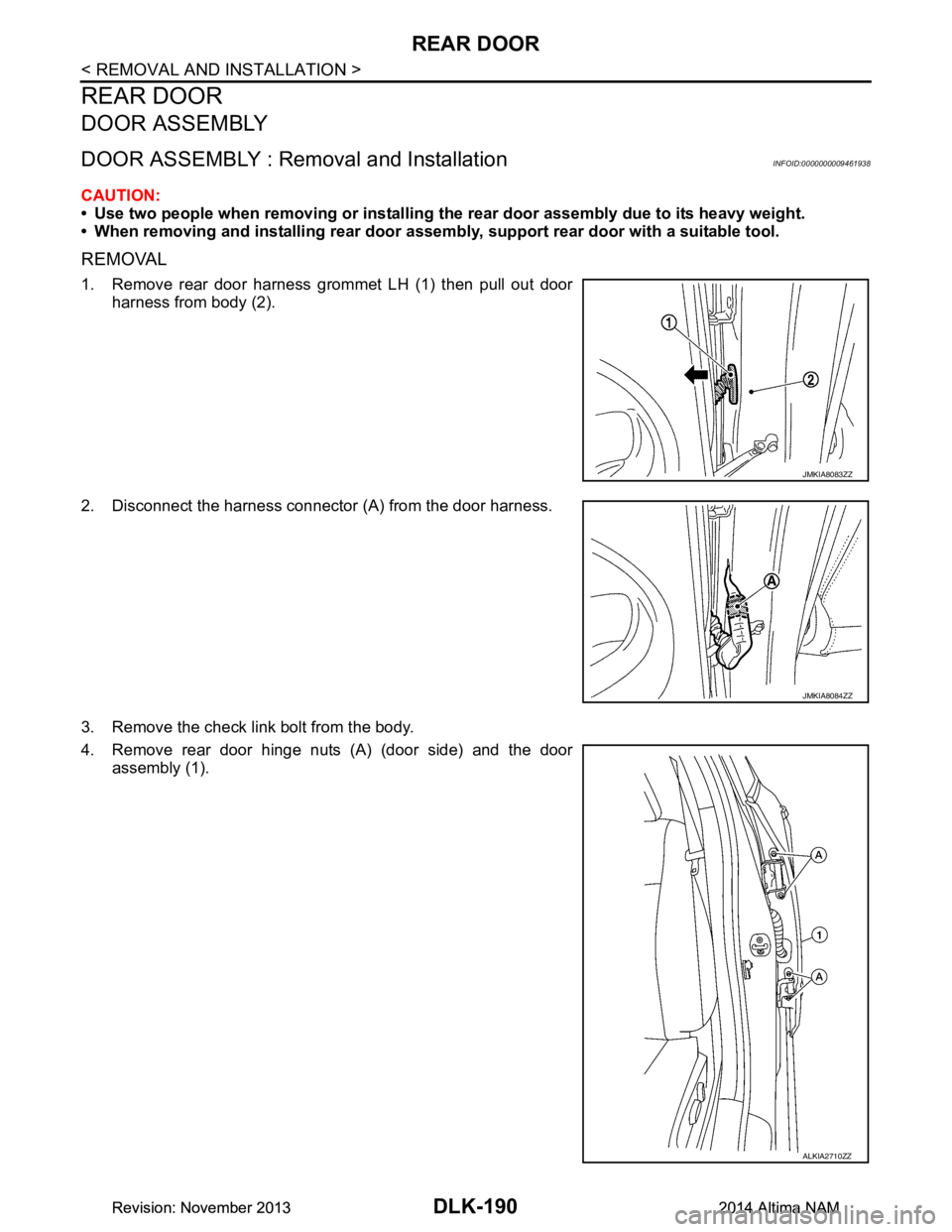
1. Remove rear door harness grommet LH (1) then pull out door
harness from body (2).
2. Disconnect the harness connector (A) from the door harness.
3. Remove the check link bolt from the body.
4. Remove rear door hinge nuts (A) (door side) and the door assembly (1).
JMKIA8083ZZ
JMKIA8084ZZ
ALKIA2710ZZ
Revision: November 20132014 Altima NAMRevision: November 20132014 Altima NAM
Page 962 of 4801
DLK-194
< REMOVAL AND INSTALLATION >
REAR DOOR
• If the clearance measurements cannot be corrected by adjusting the rear door, adjust the front door.
Refer to DLK-186, "DOOR ASSEMBLY : Adjustment"
.
DOOR STRIKER ADJUSTMENT
Adjust rear door striker so that it becomes parallel with door lock insertion direction.
DOOR STRIKER
DOOR STRIKER : Removal and InstallationINFOID:0000000009461940
REMOVAL
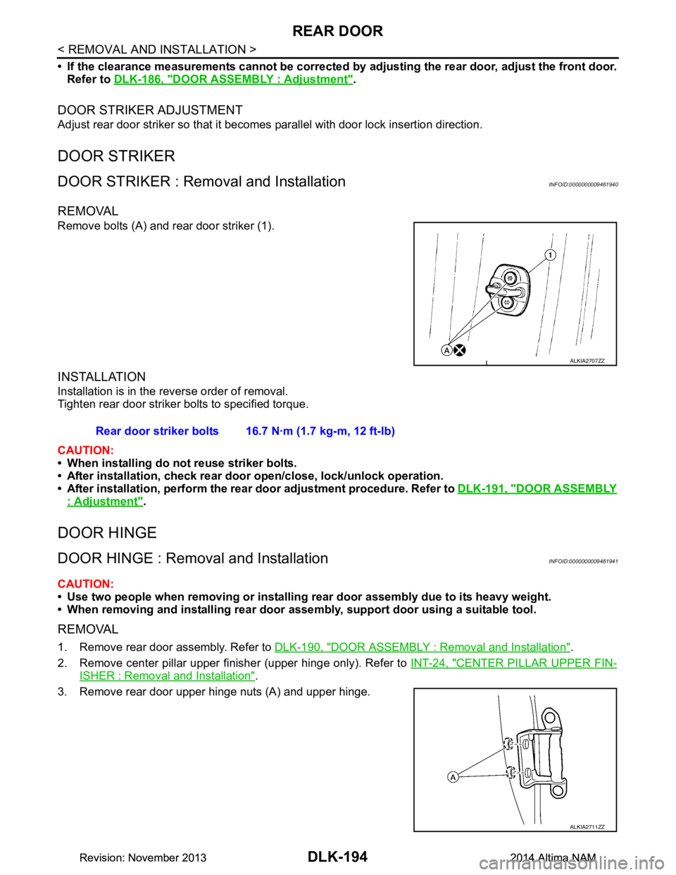
Remove bolts (A) and rear door striker (1).
INSTALLATION
Installation is in the reverse order of removal.
Tighten rear door striker bolts to specified torque.
CAUTION:
• When installing do not reuse striker bolts.
• After installation, check rear door open/close, lock/unlock operation.
• After installation, perform the rear door adjustment procedure. Refer to DLK-191, "DOOR ASSEMBLY
: Adjustment".
DOOR HINGE
DOOR HINGE : Removal and InstallationINFOID:0000000009461941
CAUTION:
• Use two people when removing or installing rear door assembly due to its heavy weight.
• When removing and installing rear door assem bly, support door using a suitable tool.
REMOVAL
1. Remove rear door assembly. Refer to DLK-190, "DOOR ASSEMBLY : Removal and Installation".
2. Remove center pillar upper finisher (upper hinge only). Refer to INT-24, "CENTER PILLAR UPPER FIN-
ISHER : Removal and Installation".
3. Remove rear door upper hinge nuts (A) and upper hinge.
ALKIA2707ZZ
Rear door striker bolts 16.7 N·m (1.7 kg-m, 12 ft-lb)
ALKIA2711ZZ
Revision: November 20132014 Altima NAMRevision: November 20132014 Altima NAM