check transmission fluid NISSAN TEANA 2014 User Guide
[x] Cancel search | Manufacturer: NISSAN, Model Year: 2014, Model line: TEANA, Model: NISSAN TEANA 2014Pages: 4801, PDF Size: 51.2 MB
Page 3219 of 4801
CHASSIS AND BODY MAINTENANCEMA-35
< PERIODIC MAINTENANCE >
C
D E
F
G H
I
J
K L
M B
MA
N
O A
CAUTION:
Do not reuse O-ring.
14. Lift down the vehicle.
15. Stop the engine.
CVT FLUID : RE0F10EINFOID:0000000009464570
CVT FLUID : InspectionINFOID:0000000009464571
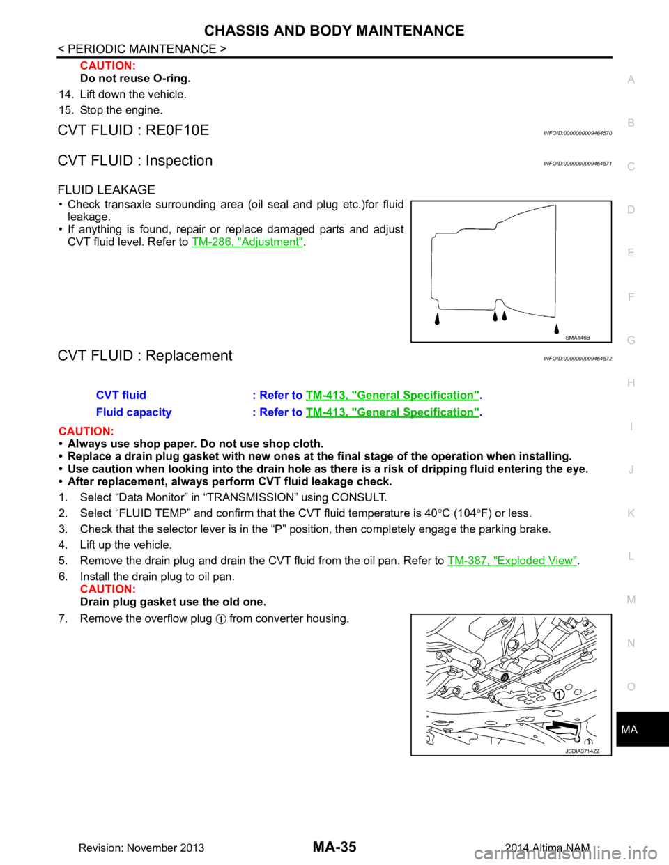
FLUID LEAKAGE
• Check transaxle surrounding area (oil seal and plug etc.)for fluid leakage.
• If anything is found, repair or replace damaged parts and adjust
CVT fluid level. Refer to TM-286, "Adjustment"
.
CVT FLUID : ReplacementINFOID:0000000009464572
CAUTION:
• Always use shop paper. Do not use shop cloth.
• Replace a drain plug gasket with new ones at the fi nal stage of the operation when installing.
• Use caution when looking into the drain hole as there is a risk of dripping fluid entering the eye.
• After replacement, always pe rform CVT fluid leakage check.
1. Select “Data Monitor” in “TRANSMISSION” using CONSULT.
2. Select “FLUID TEMP” and confirm t hat the CVT fluid temperature is 40°C (104 °F) or less.
3. Check that the selector lever is in the “P ” position, then completely engage the parking brake.
4. Lift up the vehicle.
5. Remove the drain plug and drain the CVT fluid from the oil pan. Refer to TM-387, "Exploded View"
.
6. Install the drain plug to oil pan. CAUTION:
Drain plug gasket use the old one.
7. Remove the overflow plug from converter housing.
SMA146B
CVT fluid : Refer to TM-413, "General Specification".
Fluid capacity : Refer to TM-413, "General Specification"
.
JSDIA3714ZZ
Revision: November 20132014 Altima NAM
Page 3221 of 4801
CHASSIS AND BODY MAINTENANCEMA-37
< PERIODIC MAINTENANCE >
C
D E
F
G H
I
J
K L
M B
MA
N
O A
34. Select “Data Monitor” in “TRANSMISSION” using CONSULT.
35. Select “CONFORM CVTF DETERIORTN”.
36. Select “Erase”.
37. Stop the engine.
CVT FLUID : AdjustmentINFOID:0000000009464573
CAUTION:
• During adjustment of the CVT fluid level, check CO NSULT so that the oil temperature may be main-
tained from 35 to 45 °C (95 to 113 °F).
• During adjustment of the CVT fluid level, check that the engine speed is maintaining 500 rpm.
• Use caution when looking into the drain hole as there is a risk of dripping fluid entering the eye.
1. Check that the selector lever is in the “P ” position, then completely engage the parking brake.
2. Start the engine.
3. Adjust the CVT fluid temperature to be approximately 40 °C (104 °F).
NOTE:
The CVT fluid is largely affected by temperature. Therefore be sure to use CONSULT and check the
“FLUID TEMP” under “TRA NSMISSION” in “Data Monitor” while adjusting.
4. While depressing the brake pedal, shift the selector leve r to the entire position from “P” to “DS”, and shift it
to the “P” position.
NOTE:
Hold the lever at each position for 5 seconds.
5. Lift up the vehicle.
6. Check that there is no CVT fluid leakage.
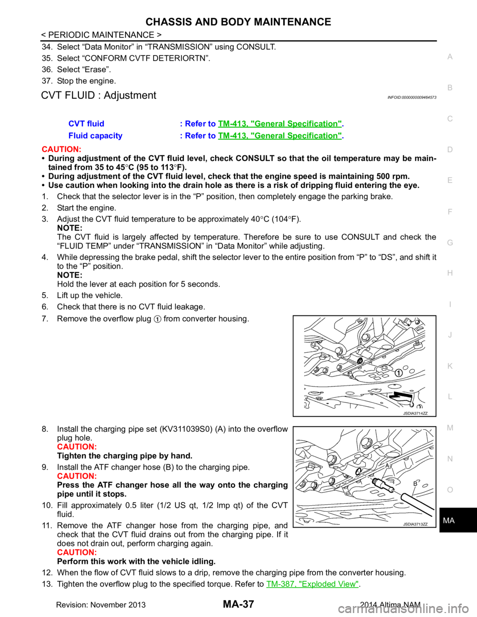
7. Remove the overflow plug from converter housing.
8. Install the charging pipe set (KV311039S0) (A) into the overflow plug hole.
CAUTION:
Tighten the charging pipe by hand.
9. Install the ATF changer hose (B) to the charging pipe. CAUTION:
Press the ATF changer hose all the way onto the charging
pipe until it stops.
10. Fill approximately 0.5 liter (1/2 US qt, 1/2 lmp qt) of the CVT
fluid.
11. Remove the ATF changer hose from the charging pipe, and check that the CVT fluid drains out from the charging pipe. If it
does not drain out, perform charging again.
CAUTION:
Perform this work with the vehicle idling.
12. When the flow of CVT fluid slows to a drip, re move the charging pipe from the converter housing.
13. Tighten the overflow plug to the specified torque. Refer to TM-387, "Exploded View"
.
CVT fluid : Refer to
TM-413, "General Specification"
.
Fluid capacity : Refer to TM-413, "General Specification"
.
JSDIA3714ZZ
JSDIA3713ZZ
Revision: November 20132014 Altima NAM
Page 4222 of 4801
TM-7
CEF
G H
I
J
K L
M A
B
TM
N
O P
Diagnosis Procedure ...........................................
..
327
P0746 PRESSURE CONTROL SOLENOID A ..328
DTC Logic ........................................................... ..328
Diagnosis Procedure .............................................329
P0776 PRESSURE CONTROL SOLENOID B ..330
DTC Logic ........................................................... ..330
Diagnosis Procedure .............................................331
P0778 PRESSURE CONTROL SOLENOID B ..332
DTC Logic ........................................................... ..332
Diagnosis Procedure .............................................332
P0779 PRESSURE CONTROL SOLENOID B ..334
DTC Logic ........................................................... ..334
Diagnosis Procedure .............................................334
P0841 TRANSMISSION FLUID PRESSURE
SEN/SW A ...................................................... ..
336
DTC Logic ........................................................... ..336
Diagnosis Procedure .............................................336
P0847 TRANSMISSION FLUID PRESSURE
SEN/SW B ...................................................... ..
337
DTC Logic ........................................................... ..337
Diagnosis Procedure .............................................337
P0848 TRANSMISSION FLUID PRESSURE
SEN/SW B ...................................................... ..
339
DTC Logic ........................................................... ..339
Diagnosis Procedure .............................................339
P084C TRANSMISSION FLUID PRESSURE
SEN/SW H ...................................................... ..
341
DTC Logic ........................................................... ..341
Diagnosis Procedure .............................................341
P084D TRANSMISSION FLUID PRESSURE
SEN/SW H ...................................................... ..
343
DTC Logic ........................................................... ..343
Diagnosis Procedure .............................................343
P0863 TCM COMMUNICATION ......................345
DTC Logic ........................................................... ..345
Diagnosis Procedure .............................................345
P0890 TCM .......................................................346
DTC Logic ........................................................... ..346
Diagnosis Procedure .............................................346
P0962 PRESSURE CONTROL SOLENOID A ..347
DTC Logic ........................................................... ..347
Diagnosis Procedure .............................................347
P0963 PRESSURE CONTROL SOLENOID A ..349
DTC Logic ........................................................... ..349
Diagnosis Procedure .............................................349
P0965 PRESSURE CONTROL SOLENOID B ..351
DTC Logic ........................................................... ..351
Diagnosis Procedure .............................................352
P0966 PRESSURE CONTROL SOLENOID B .353
DTC Logic ............................................................ ..353
Diagnosis Procedure .............................................353
P0967 PRESSURE CONTROL SOLENOID B .355
DTC Logic ............................................................ ..355
Diagnosis Procedure .............................................355
P2765 INPUT SPEED SENSOR B ..................357
DTC Logic ..............................................................357
Diagnosis Procedure .............................................358
P2813 SELECT SOLENOID ...........................360
DTC Logic ..............................................................360
Diagnosis Procedure .............................................361
P2814 SELECT SOLENOID ...........................362
DTC Logic ..............................................................362
Diagnosis Procedure .............................................362
P2815 SELECT SOLENOID ...........................364
DTC Logic ..............................................................364
Diagnosis Procedure .............................................364
MAIN POWER SUPPLY AND GROUND CIR-
CUIT ................................................................
366
Diagnosis Procedure ........................................... ..366
SHIFT POSITION INDICATOR CIRCUIT ........368
Component Parts Function Inspection ..................368
Diagnosis Procedure .............................................368
SHIFT LOCK SYSTEM ...................................369
Component Function Check ..................................369
Diagnosis Procedure .............................................369
Component Inspection (Shift Lock Solenoid) ........371
Component Inspection (Park Position Switch) ......371
Component Inspection (Stop Lamp Switch) ..........372
SYMPTOM DIAGNOSIS ............................373
CVT CONTROL SYSTEM ...............................373
Symptom Table ................................................... ..373
PERIODIC MAINTENANCE ......................377
CVT FLUID ......................................................377
Inspection ............................................................ ..377
REMOVAL AND INSTALLATION .............378
CVT SHIFT SELECTOR ..................................378
Exploded View ..................................................... ..378
Removal and Installation .......................................378
Inspection ..............................................................379
CONTROL CABLE ..........................................380
Exploded View .......................................................380
Removal and Installation .......................................380
Inspection and Adjustment ....................................381
PADDLE SHIFTER ..........................................382
Revision: November 20132014 Altima NAMRevision: November 20132014 Altima NAM
Page 4246 of 4801

SYSTEMTM-31
< SYSTEM DESCRIPTION > [CVT: RE0F10D]
C
EF
G H
I
J
K L
M A
B
TM
N
O P
• CVT detects the vehicle driving status from switc hes, sensors and signals, and controls the vehicle so that
the optimum shift position and shift timing may always be achieved. It also controls the vehicle to reduce
shift and lockup shock, etc.
• Receives input signals from switches and sensors.
• Sends the output signal necessary for operation of so lenoid valves, and evaluates the line pressure, shift
timing, lockup operation, engine brake performance, etc.
• If a malfunction occurs on the electric system, activa te the fail-safe mode only to drive the vehicle.
LIST OF CONTROL ITEMS AND INPUT/OUTPUT
*: If these input/output signals show errors, TCM activates the fail-safe function.
CVT CONTROL SYSTEM : Fail-safeINFOID:0000000009463988
TCM has a fail-safe mode. The mode functions so that operation can be continued even if the signal circuit of
the main electronically controlled input/output parts is damaged.
If the vehicle shows following behaviors including “poor acceleration”, a malfunction of the applicable system
is detected by TCM and the vehicle may be in a fail-s afe mode. At this time, check the DTC code and perform
inspection and repair according to the malfunction diagnosis procedures.
Fail-safe function
Control Item Shift control Line pressure
control Select control Lock-up con-
trol Fail-safe func-
tion*
Input Engine torque signal
(CAN communication) ×××××
Engine speed signal
(CAN communication) ×××××
Accelerator pedal position signal
(CAN communication) ××××
Closed throttle position signal
(CAN communication) ×× ×
Stop lamp switch signal
(CAN communication) ××××
Primary pressure sensor ×
Secondary pressure sensor ×× ×
CVT fluid temperature sensor ×××××
Primary speed sensor ×××××
Output speed sensor ×× ××
Input speed sensor ×××××
Transmission range switch ×××××
Overdrive control switch
(CAN communication) ×× ×
Output Line pressure solenoid valve
××× ×
Primary pressure solenoid valve ×× ×
Torque converter clutch solenoid
valve ××
Secondary pressure solenoid valve ×× ×
Select solenoid valve ×××
Shift position indicator
(CAN communication) ×
O/D OFF indicator lamp
(CAN communication) ×
Revision: November 20132014 Altima NAMRevision: November 20132014 Altima NAM
Page 4274 of 4801

TCM
TM-59
< ECU DIAGNOSIS INFORMATION > [CVT: RE0F10D]
C
EF
G H
I
J
K L
M A
B
TM
N
O P
Protection Control INFOID:0000000009464003
The TCM becomes the protection control status temporar ily to protect the safety when the safety of TCM and
transmission is lost. It automatically returns to the normal status if the safety is secured.
The TCM has the following protection control.
CONTROL FOR WHEEL SPIN
TORQUE IS REDUCED WHEN DRIVING WITH THE REVERSE GEAR
CONTROL WHEN FLUID TEMPERATURE IS HIGH
REVERSE PROHIBIT CONTROL
DTC Inspection Priority ChartINFOID:0000000009464004
If multiple malfunction codes are detected at the same time, check each code according to the DTC check pri-
ority list below.
Control When a wheel spin is detected, the engine output and gear ratio are limited and the line pressure is increased.
Limits engine output when a wheel spin occurs in any of right and left drive wheels.
Vehicle behavior in
control If the accelerator is kept depressing during wheel spin, the engine revolution and vehicle speed are limited to
a certain degree.
Normal return condi-
tion Wheel spin convergence returns the control to the normal control.
Control Engine output is controlled according to a vehicle speed while reversing the vehicle.
Vehicle behavior in
control Power performance may be lowered while reversing the vehicle.
Normal return condi-
tion Torque returns to normal by positioning the sele
ctor lever in a range other than “R” position.
Control When the CVT fluid temperature is high, the gear shift permission maximum revolution and the maximum
torque are reduced than usual to prevent increase of the oil temperature.
Vehicle behavior in
control Power performance may be lowered, compared to normal control.
Normal return condi-
tion The control returns to the normal control when CVT fluid temperature is lowered.
ControlThe reverse brake is controlled to avoid becoming engaged when the selector lever is set in “R” position while
driving in forward direction at more than the specified speed.
Vehicle behavior in
control If the selector lever is put at “R” position when driving with the forward gear, the gear becomes neutral, not
reverse.
Normal return condi-
tion The control returns to normal control when the vehicle is driven at low speeds. (The reverse brake becomes
engaged.)
Priority DTC (Diagnostic Trouble Code) Reference
1 P0863 CONTROL UNIT (CAN)
TM-143, "DTC Logic"
U0073 COMM BUS A OFF TM-88, "DTC Logic"
U0100 LOST COMM (ECM A)TM-89, "DTC Logic"
U0140 LOST COMM (BCM)TM-90, "DTC Logic"
U0141 LOST COMM (BCM A)TM-91, "DTC Logic"
U0155 LOST COMM (IPC)TM-92, "DTC Logic"
U0300 CAN COMM DATA TM-93, "DTC Logic"
U1000 CAN COMM CIRCTM-94, "DTC Logic"
U1117 LOST COMM (ABS)TM-95, "DTC Logic"
Revision: November 20132014 Altima NAMRevision: November 20132014 Altima NAM
Page 4275 of 4801

TM-60
< ECU DIAGNOSIS INFORMATION >[CVT: RE0F10D]
TCM
DTC Index
INFOID:0000000009464005
NOTE:
• If multiple malfunction codes are detected at the same time, check each code according to the “DTC check
priority list”. Refer to TM-59, "DTC Inspection Priority Chart"
.
• The ignition counter is displayed in “FFD”. Refer to TM-43, "CONSULT Function"
.
2P0740 TORQUE CONVERTER
TM-120, "DTC Logic"
P0743 TORQUE CONVERTERTM-122, "DTC Logic"
P0778 PC SOLENOID BTM-130, "DTC Logic"
P0779 PC SOLENOID BTM-132, "DTC Logic"
P0962 PC SOLENOID ATM-145, "DTC Logic"
P0963 PC SOLENOID ATM-147, "DTC Logic"
P0966 PC SOLENOID BTM-151, "DTC Logic"
P0967 PC SOLENOID BTM-153, "DTC Logic"
P2814 SELECT SOLENOIDTM-160, "DTC Logic"
P2815 SELECT SOLENOIDTM-162, "DTC Logic"
3P062F EEPROM
TM-96, "DTC Logic"
P0705 T/M RANGE SENSOR ATM-97, "DTC Logic"
P0706 T/M RANGE SENSOR ATM-103, "DTC Logic"
P0711 FLUID TEMP SENSOR ATM-106, "DTC Logic"
P0712 FLUID TEMP SENSOR A TM-110, "DTC Logic"
P0713 FLUID TEMP SENSOR ATM-112, "DTC Logic"
P0715 INPUT SPEED SENSOR ATM-114, "DTC Logic"
P0717 INPUT SPEED SENSOR ATM-117, "DTC Logic"
P0841 FLUID PRESS SEN/SW ATM-134, "DTC Logic"
P0847 FLUID PRESS SEN/SW BTM-135, "DTC Logic"
P0848 FLUID PRESS SEN/SW BTM-137, "DTC Logic"
P084C FLUID PRESS SEN/SW HTM-139, "DTC Logic"
P084D FLUID PRESS SEN/SW HTM-141, "DTC Logic"
P0890 TCMTM-144, "DTC Logic"
P2765 INPUT SPEED SENSOR BTM-155, "DTC Logic"
4P0744 TORQUE CONVERTER
TM-124, "DTC Logic"
P0746 PC SOLENOID ATM-126, "DTC Logic"
P0776 PC SOLENOID BTM-128, "DTC Logic"
P0965 PC SOLENOID BTM-149, "DTC Logic"
P2813 SELECT SOLENOIDTM-158, "DTC Logic"
Priority DTC (Diagnostic Trouble Code) Reference
DTC*1, *2
Items
(CONSULT screen terms) Trip
MIL*3Reference
GST CONSULT
(TRANSMISSION)
P062F P062F EEPROM 1 ON TM-96
P0705 P0705 T/M RANGE SENSOR A 2 ONTM-97
P0706 P0706 T/M RANGE SENSOR A 2 ONTM-103
P0711 P0711 FLUID TEMP SENSOR A 2 ONTM-106
P0712 P0712 FLUID TEMP SENSOR A 2 ON TM-110
P0713 P0713 FLUID TEMP SENSOR A 2 ONTM-112
Revision: November 20132014 Altima NAMRevision: November 20132014 Altima NAM
Page 4296 of 4801

ADDITIONAL SERVICE WHEN REPLACING TRANSAXLE ASSEMBLY
TM-81
< BASIC INSPECTION > [CVT: RE0F10D]
C
EF
G H
I
J
K L
M A
B
TM
N
O P
ADDITIONAL SERVICE WHEN RE PLACING TRANSAXLE ASSEMBLY
DescriptionINFOID:0000000009464012
Perform the following work after the transaxle assembly is replaced.
ERASING AND WRITING TCM DATA• TCM performs accurate control by retrieving data (inher ent characteristic value) of each solenoid. For this
reason, after replacing transaxle assembly, it is nec essary to erase data stored in TCM and write new data.
ERASING OF CVT FLUID DEGRADATION LEVEL DATA • TCM records the degradation level of the CVT fluid calc ulated from the vehicle driving status. Therefore, if
the transaxle assembly is replaced, it is necessary to erase the CVT fluid degradation level data recorded by
TCM.
Work ProcedureINFOID:0000000009464013
1.CHECK THE SERIAL NUMBER (PART 1)
Write down the serial number of new transaxle assembly.
>> GO TO 2.
2.CHECK THE SERIAL NUMBER (PART 2)
1. Turn ignition switch ON.
2. Insert the attached CD into CONSULT.
3. Select “Work Support” in “TRANSMISSION”.
4. Select “WRITE IP CHARA - REPLACEMENT AT/CVT”.
5. Check that the serial number displayed on CO NSULT screen and those written in the memo agree.
CAUTION:
Never perform writing procedure.
6. Go back to MENU of “Work Support”.
>> GO TO 3.
3.INITIALIZE TCM
1. Set parking brake.
2. Select “ERASE MEMORY DATA”.
3. Touch “Start” according to the instructions on the CONSULT screen.
Is
“COMPLETED” displayed?
YES >> GO TO 4.
NO >> Turn ignition switch OFF and wait for a mi nimum of 10 seconds then perform the work again.
JSDIA4208GB
Revision: November 20132014 Altima NAMRevision: November 20132014 Altima NAM
Page 4298 of 4801

CVT FLUIDTM-83
< BASIC INSPECTION > [CVT: RE0F10D]
C
EF
G H
I
J
K L
M A
B
TM
N
O P
CVT FLUID
ReplacementINFOID:0000000009464014
CAUTION:
• Always use shop paper. Never use shop cloth.
• Replace a drain plug gasket with new ones at the fi nal stage of the operation when installing.
• Use caution when looking into the drain hole as there is a risk of dripping fluid entering the eye.
• After replacement, always pe rform CVT fluid leakage check.
1. Select “Data Monitor” in “TRANSMISSION” using CONSULT.
2. Select “FLUID TEMP” and confirm t hat the CVT fluid temperature is 40°C (104 °F) or less.
3. Check that the selector lever is in the “P ” position, then completely engage the parking brake.
4. Lift up the vehicle.
5. Remove the drain plug and drain the CVT fluid from the oil pan. Refer to TM-186, "Exploded View"
.
6. Install the drain plug to oil pan. CAUTION:
Drain plug gasket use the old one.
7. Remove the overflow plug from converter housing.
8. Install the charging pipe set (KV311039S0) (A) into the overflow plug hole.
CAUTION:
Tighten the charging pipe by hand.
9. Install the ATF changer hose (B) to the charging pipe. CAUTION:
Press the ATF changer hose all the way onto the charging
pipe until it stops.
10. Fill approximately 3 liter (2-5 /8 lmp qt) of the CVT fluid.
11. Remove the ATF changer hose and charging pipe, then install the overflow plug.
NOTE:
Perform this work quickly because CVT fluid leaks.
12. Lift down the vehicle.
13. Start the engine.
14. While depressing the brake pedal, shift the selector leve r to the entire position from “P” to “DS”, and shift it
to the “P” position.
NOTE:
Hold the lever at each position for 5 seconds.
15. Check that the CONSULT “Data Monitor” in “FLUID TEMP” is 35°C (95 °F) to 45 °C (113 °F).
16. Stop the engine.
17. Lift up the vehicle.
18. Remove the drain plug, and then drain CVT fluid from oil pan. CVT fluid : Refer to
TM-212, "General Specification"
.
Fluid capacity : Refer to TM-212, "General Specification"
.
JSDIA3714ZZ
JSDIA3713ZZ
Revision: November 20132014 Altima NAMRevision: November 20132014 Altima NAM
Page 4299 of 4801

TM-84
< BASIC INSPECTION >[CVT: RE0F10D]
CVT FLUID
19. Repeat steps 8 to 18 (one time).
20. Tighten the drain plug to the specified torque. Refer to TM-186, "Exploded View"
.
21. Remove the overflow plug.
22. Install the charging pipe set (KV311039S0) into the overflow plug hole. CAUTION:
Tighten the charging pipe by hand.
23. Install the ATF changer hose to the charging pipe. CAUTION:
Press the ATF changer hose all the way onto the charging pipe until it stops.
24. Fill approximately 3 liter (2-5/8 lmp qt) of the CVT fluid.
25. Remove the ATF changer hose and charging pipe, then install the overflow plug. NOTE:
Perform this work quickly because CVT fluid leaks.
26. Lift down the vehicle.
27. Start the engine.
28. While depressing the brake pedal, shift the selector lever to the entire position from “P” to “DS”, and shift it to the “P” position.
NOTE:
Hold the lever at each position for 5 seconds.
29. Check that the CONSULT “Data Monitor” in “FLUID TEMP” is 35 °C (95 °F) to 45 °C (113 °F).
30. Lift up the vehicle.
31. Remove the overflow plug and confirm that the CV T fluid is drained from the overflow plug hole.
CAUTION:
Perform this work with the vehicle idling.
NOTE:
If the CVT fluid is not drained, refer to “Adjustment” and refill with the CVT fluid.
32. When the flow of CVT fluid slows to a drip, tighten the overflow plug to the specified torque. Refer to TM-
186, "Exploded View".
CAUTION:
Never reuse O-ring.
33. Lift down the vehicle.
34. Select “Data Monitor” in “T RANSMISSION” using CONSULT.
35. Select “CONFORM CVTF DETERIORTN”.
36. Select “Erase”.
37. Stop the engine.
AdjustmentINFOID:0000000009464015
CAUTION:
• During adjustment of the CVT fluid level, check CO NSULT so that the oil temperature may be main-
tained from 35 to 45 °C (95 to 113 °F).
• During adjustment of the CVT fluid level, check that the engine speed is maintaining 500 rpm.
• Use caution when looking into the drain hole as th ere is a risk of dripping fluid entering the eye.
1. Check that the selector lever is in the “P ” position, then completely engage the parking brake.
2. Start the engine.
3. Adjust the CVT fluid temperature to be approximately 40 °C (104 °F).
NOTE:
The CVT fluid is largely affected by temperature. Therefore be sure to use CONSULT and check the
“FLUID TEMP” under “TRANSMISSION” in “Data Monitor” while adjusting.
4. While depressing the brake pedal, shift the selector lever to the entire position from “P” to “DS”, and shift it to the “P” position.
NOTE: CVT fluid : Refer to
TM-212, "General Specification"
.
Fluid capacity : Refer to TM-212, "General Specification"
.
Revision: November 20132014 Altima NAMRevision: November 20132014 Altima NAM
Page 4322 of 4801

P0711 TRANSMISSION FLUID TEMPERATURE SENSOR A
TM-107
< DTC/CIRCUIT DIAGNOSIS > [CVT: RE0F10D]
C
EF
G H
I
J
K L
M A
B
TM
N
O P
8. Stop the vehicle.
9. Check the first trip DTC.
With GST
1. Turn ignition switch OFF and cool the engine.
2. Start the engine and wait for at least 2 minutes.
3. Drive the vehicle and maintain the following conditions for 20 minutes or more.
4. Stop the vehicle.
5. Check the first trip DTC.
Is
“P0711” detected?
YES >> Go to TM-107, "Diagnosis Procedure".
NO >> GO TO 3.
3.CHECK CVT FLUID TEMPERATURE SENSOR
1. Turn ignition switch OFF.
2. Disconnect CVT unit connector.
3. Check resistance between CVT unit connector terminals.
Is the inspection result normal?
YES >> INSPECTION END
NO >> There is a malfunction of CVT fluid temperat ure sensor. Replace transaxle assembly. Refer to
TM-206, "Removal and Installation"
.
Diagnosis ProcedureINFOID:0000000009464047
1.CHECK CVT FLUID TEMPERATURE SENSOR
1. Turn ignition switch OFF.
2. Disconnect CVT unit connector.
3. Check resistance between CVT unit connector terminals.
Selector lever : “D” position
Accelerator pedal position : 1.0/8 or more
Vehicle speed : 10 km/h (7 MPH) or more
CVT fluid temperature before engine start Driving time
− 40 °C ( −40 °F) – −31 °C ( −23.8 °F) 20 minutes or more
− 30 °C ( −22 °F) – −21 °C ( −5.8 °F) 18 minutes or more
− 20 °C ( −4°F) – −11 °C ( −12.2 °F) 14 minutes or more
− 10 °C (14 °F) – −1 °C (30.2 °F) 10 minutes or more
0 °C (32 °F) – 9 °C (48.2 °F) 7 minutes or more
Other than the above —
(Go to 3.)
Selector lever : “D” position
Accelerator pedal position : 1.0/8 or more
Vehicle speed : 10 km/h (7 MPH) or more
CVT unit Condition Resistance
(Approx.)
Te r m i n a l
12 – 18 CVT fluid temperature: 20
°C (68 °F) 6.5 k Ω
CVT fluid temperature: 50 °C (122 °F) 2.2 k Ω
CVT fluid temperature: 80 °C (176 °F) 0.87 k Ω
Revision: November 20132014 Altima NAMRevision: November 20132014 Altima NAM