checking oil NISSAN TEANA 2014 User Guide
[x] Cancel search | Manufacturer: NISSAN, Model Year: 2014, Model line: TEANA, Model: NISSAN TEANA 2014Pages: 4801, PDF Size: 51.2 MB
Page 2055 of 4801
![NISSAN TEANA 2014 User Guide
CAMSHAFTEM-57
< REMOVAL AND INSTALLATION > [QR25DE]
C
D E
F
G H
I
J
K L
M A
EM
NP
O
WARNING:
Check when engine is cold so as to preven t burns from any splashing engine oil.
CAUTION:
Perform this i](/img/5/57390/w960_57390-2054.png "NISSAN TEANA 2014 User Guide
CAMSHAFTEM-57
< REMOVAL AND INSTALLATION > [QR25DE]
C
D E
F
G H
I
J
K L
M A
EM
NP
O
WARNING:
Check when engine is cold so as to preven t burns from any splashing engine oil.
CAUTION:
Perform this i")
CAMSHAFTEM-57
< REMOVAL AND INSTALLATION > [QR25DE]
C
D E
F
G H
I
J
K L
M A
EM
NP
O
WARNING:
Check when engine is cold so as to preven t burns from any splashing engine oil.
CAUTION:
Perform this inspection only when DTC P0011, P0014, P052A, P052B is detected in self-diagnostic
results of CONSULT and it is directed according to inspection procedure of EC section. Refer to EC-
210, "Diagnosis Procedure".
1. Check engine oil level and adjust oil level as necessary. Refer to LU-9, "Inspection"
.
2. Remove the intake valve timing intermediate lock control solenoid valve, intake valve timing control sole- noid valve, and exhaust valve timing control solenoid valve. Refer to EM-58, "Intake Valve Timing Interme-
diate Lock Control Solenoid Valve, Intake Valve Timing Control Solenoid Valve, and Exhaust Valve Timing
Control Solenoid Valve".
3. Perform the following procedure to prevent the engi ne from being unintentionally started while checking.
a. Release fuel pressure. Refer to EC-182, "Work Procedure"
.
b. Disconnect injector harness connectors.
4. Crank engine, and then make sure that engine oil comes out of the valve timing control cover oil holes (A). End cranking after
checking.
WARNING:
Be careful not to touch rotating parts (drive belt, crankshaft
pulley, etc.).
CAUTION:
• Engine oil may squirt from intake valve timing intermedi-
ate lock control solenoid valve, intake valve timing control
solenoid valve, exhaust valve timing control solenoid
valve installation holes during cranking. Use a shop cloth
to prevent engine oil from splashing on worker, engine
components and vehicle.
• Do not allow engine oil to get on rubber componen ts such as drive belts or engine mount insula-
tors. Immediately wipe off any splashed engine oil.
5. If engine oil does not come out from valve timing cont rol cover oil holes (A), diagnose problem in lubrica-
tion circuit such as dirty oil groove between oil strainer and intake valve timing intermediate lock control
solenoid valve, intake valve timing control solenoid valve, or exhaust valve timing control solenoid valve.
Refer to LU-7, "Lubrication Circuit"
.
a. Remove components between intake valve timing intermediate lock control solenoid valve, intake valve timing control solenoid valve, exhaust valve timing c ontrol solenoid valve and camshaft sprocket (INT) or
camshaft sprocket (EXH), (if necessary) and then check each oil groove for clogging.
b. Clean oil groove if necessary. Refer to LU-7, "Lubrication Circuit"
.
6. After inspection, install the remaining components in the reverse order of removal.
ALBIA0909GB
Revision: November 20132014 Altima NAM
Page 2136 of 4801
![NISSAN TEANA 2014 User Guide
EM-138
< PERIODIC MAINTENANCE >[VQ35DE]
CAMSHAFT VALVE CLEARANCE
CAMSHAFT VALVE CLEARANCE
Valve ClearanceINFOID:0000000009460535
CHECKING
• Perform inspection as follows after removal, installation](/img/5/57390/w960_57390-2135.png "NISSAN TEANA 2014 User Guide
EM-138
< PERIODIC MAINTENANCE >[VQ35DE]
CAMSHAFT VALVE CLEARANCE
CAMSHAFT VALVE CLEARANCE
Valve ClearanceINFOID:0000000009460535
CHECKING
• Perform inspection as follows after removal, installation")
EM-138
< PERIODIC MAINTENANCE >[VQ35DE]
CAMSHAFT VALVE CLEARANCE
CAMSHAFT VALVE CLEARANCE
Valve ClearanceINFOID:0000000009460535
CHECKING
• Perform inspection as follows after removal, installation or replace-
ment of camshaft or valve related parts, or if there is unusual
engine conditions regarding valve clearance.
Check valve clearance while engine is cold and not running.
1. Remove the intake manifold collector. Refer to EM-146,
"Removal and Installation".
2. Remove the ignition coils and spark plugs. Refer to EM-132,
"Removal and Installation".
3. Remove the rocker covers. Refer to EM-168, "Removal and
Installation LH" (LH), EM-169, "Removal and Installation RH"
(RH).
4. Set No.1 cylinder at TDC on its compression stroke. • Align pointer with TDC mark on crankshaft pulley.
• Check that the valve lifters on No.1 cylinder are loose and valve lifters on No.4 are tight. If not, turn the crankshaft one full
revolution (360 °) and align as shown.SEM713A
JMBIA1135GB
SEM418G
Revision: November 20132014 Altima NAM
Page 2140 of 4801
![NISSAN TEANA 2014 User Guide
EM-142
< PERIODIC MAINTENANCE >[VQ35DE]
COMPRESSION PRESSURE
COMPRESSION PRESSURE
On-Vehicle ServiceINFOID:0000000009460536
CHECKING COMPRESSION PRESSURE
1. Run the engine until it reaches normal ope](/img/5/57390/w960_57390-2139.png "NISSAN TEANA 2014 User Guide
EM-142
< PERIODIC MAINTENANCE >[VQ35DE]
COMPRESSION PRESSURE
COMPRESSION PRESSURE
On-Vehicle ServiceINFOID:0000000009460536
CHECKING COMPRESSION PRESSURE
1. Run the engine until it reaches normal ope")
EM-142
< PERIODIC MAINTENANCE >[VQ35DE]
COMPRESSION PRESSURE
COMPRESSION PRESSURE
On-Vehicle ServiceINFOID:0000000009460536
CHECKING COMPRESSION PRESSURE
1. Run the engine until it reaches normal operating temperature.
2. Turn the ignition switch to OFF.
3. Release fuel pressure and leave t he fuel pump electrically disconnected.
Refer to EC-687, "Work Procedure"
.
4. Remove all six spark plugs. Refer to EM-132, "Removal and Installation"
.
5. Install the compression tester with the adapter into the spark plug hole. • Use compression tester whose end (a) (rubber portion) is
smaller than 20 mm (0.79 in) in diameter. Otherwise, it may be
caught by cylinder head during removal.
6. Depress accelerator pedal fully to keep the electric throttle control actuator butterfly-valve wide open to
maximize air intake flow.
7. Crank the engine and record the highest gauge indication.
8. Repeat the measurement on each cylinder (steps 5 - 7). NOTE:
Always use a fully charged battery to obtain specified engine speed.
Unit: kPa (kg/cm2, psi)/rpm
9. If compression in one or more cylinders is low:
a. Pour a small amount of engine oil into cylinders through the spark plug holes.
b. Retest compression (steps 5 - 8).
• If adding oil helps raise compression pressure, then the piston rings may be worn or damaged. If so, replace piston rings after checking piston.
• If the pressure stays low, a valve may be sticking or is seating improperly. Inspect and repair the valve and/
or valve seat. Refer to EM-212, "Inspection After Disassembly"
. If the valve and/or valve seat is damaged
replace as necessary.
• If compression stays low in two or more cylinders that are next to each other:
- The cylinder head gasket may be leaking.
- Both cylinders may have valve component damage. Inspect and repair as necessary.
JPBIA0171ZZ
Standard Minimum Difference limit between cylinders
1,275 (13.0, 185)/300 981 (10.0, 142)/300 98 (1.0, 14)/300
Revision: November 20132014 Altima NAM
Page 2163 of 4801
![NISSAN TEANA 2014 User Guide
FUEL INJECTOR AND FUEL TUBEEM-165
< REMOVAL AND INSTALLATION > [VQ35DE]
C
D E
F
G H
I
J
K L
M A
EM
NP
O
10. Loosen bolts in reverse order as shown, and remove fuel tube
and fuel injector assembly.](/img/5/57390/w960_57390-2162.png "NISSAN TEANA 2014 User Guide
FUEL INJECTOR AND FUEL TUBEEM-165
< REMOVAL AND INSTALLATION > [VQ35DE]
C
D E
F
G H
I
J
K L
M A
EM
NP
O
10. Loosen bolts in reverse order as shown, and remove fuel tube
and fuel injector assembly.")
FUEL INJECTOR AND FUEL TUBEEM-165
< REMOVAL AND INSTALLATION > [VQ35DE]
C
D E
F
G H
I
J
K L
M A
EM
NP
O
10. Loosen bolts in reverse order as shown, and remove fuel tube
and fuel injector assembly.
CAUTION:
Do not tilt fuel tube, or remain ing fuel in pipes may flow out
from pipes.
11. Remove fuel injector from fuel tube as follows:
a. Open and remove clip (1).
b. Remove fuel injector (2) from fuel tube (5) by pulling straight. CAUTION:
• Do not reuse O-rings.
• Be careful with remaining fuel that may go out from fuel
tube.
• Be careful not to damage in jector nozzle during removal.
• Do not bump or drop fuel injector.
• Do not disassemble fuel injector.
12. Remove fuel damper from fuel tube, (if necessary).
INSTALLATION
1. Install fuel damper as follows:
a. Install new O-ring (2) to fuel tube (1) as shown. When handling new O-ring, be careful of the following:
CAUTION:
• Do not reuse O-ring.
• Handle O-ring with bare hands. Do not wear gloves.
• Lubricate O-ring with new engine oil.
• Do not clean O-ring with solvent.
• Check that O-ring and its mating part are free of foreign material.
• When installing O-ring, be car eful not to scratch it with
tool or fingernails. Also be careful not to twist or stretch
O-ring. If O-ring was stretched while it was being
attached, do not insert it quickly into fuel tube.
• Insert new O-ring straight into fuel tube. Do not twist it.
b. Install spacer (3) to fuel damper (4).
c. Insert fuel damper straight into fuel tube. CAUTION:
• Insert straight, checking that the axis is lined up.
• Do not pressure-fit with excessive force.
• Insert fuel damper until (B) is touching (A) of fuel tube.
d. Tighten bolts evenly in turn. • After tightening bolts, check that there is no gap between fuel damper cap (5) and fuel tube.
2. Install new O-rings to fuel injector paying attention to the following. CAUTION:
: Engine front
JPBIA1715ZZ
(3) : O-ring (green)
(4) : O-ring (black)
(A) : Installed condition
(B) : Clip groove
JPBIA1958ZZ
Reference value : 130 N (13.3 kg, 29.2 lb)
JPBIA0316ZZ
Revision: November 20132014 Altima NAM
Page 2164 of 4801
![NISSAN TEANA 2014 User Guide
EM-166
< REMOVAL AND INSTALLATION >[VQ35DE]
FUEL INJECTOR AND FUEL TUBE
• Do not reuse O-rings.
• Upper and lower O-rings are different. Be careful not to confuse them.
• Handle O-ring with b](/img/5/57390/w960_57390-2163.png "NISSAN TEANA 2014 User Guide
EM-166
< REMOVAL AND INSTALLATION >[VQ35DE]
FUEL INJECTOR AND FUEL TUBE
• Do not reuse O-rings.
• Upper and lower O-rings are different. Be careful not to confuse them.
• Handle O-ring with b")
EM-166
< REMOVAL AND INSTALLATION >[VQ35DE]
FUEL INJECTOR AND FUEL TUBE
• Do not reuse O-rings.
• Upper and lower O-rings are different. Be careful not to confuse them.
• Handle O-ring with bare hands. Do not wear gloves.
• Lubricate O-ring with new engine oil.
• Do not clean O-ring with solvent.
• Check that O-ring and its mating pa rt are free of foreign material.
• When installing O-ring, be careful not to scratch it with tool or fingernails. Also be careful not to
twist or stretch O-ring. If O-ring was stretc hed while it was being attached, do not insert it
quickly into fuel tube.
• Insert O-ring straight into fu el injector. Do not twist it.
3. Install fuel injector to fuel tube as follows:
a. Insert clip (3) into clip groove (F) on fuel injector (5).
• Insert clip so that protrusion (E ) of fuel injector matches cutout
(C) of clip.
CAUTION:
• Do not reuse O-rings.
• Do not reuse clip. Replace it with new one.
• Be careful to keep clip from interfering with O-ring. If interference occurs, replace O-ring.
b. Insert fuel injector into fuel tube (1) with clip attached. • Insert it while matching it to the axial center.
• Insert fuel injector so that protrusion (A) of fuel tube matches
cutout (B) of clip.
• Check that fuel tube flange (G) is securely fixed in flange fixing
groove (D) on clip.
c. Check that installation is complete by checking that fuel injector does not rotate or come off.
• Check that protrusions of fuel injectors and fuel tubes are
aligned with cutouts of clips after installation.
4. Install fuel tube and fuel injector assembly to intake manifold. CAUTION:
Be careful not to let tip of injector nozzle come in contact with other parts.
• Tighten bolts in two steps in numerical order as shown.
5. Connect fuel injector harness.
6. Install intake manifold collector. Refer to EM-146, "Removal and Installation"
.
7. Connect quick connector between fuel feed hose and fuel tube connection with the following procedure:
a. Check no foreign substances are deposited in and around fuel tube and quick connector, and no damage on them.Fuel tube side : Black
Nozzle side : Green
(2) : O-ring (black)
(4) : O-ring (green)
JPBIA1959ZZ
: Engine front
1st step : 10.1 N·m (1.0 kg-m, 7 ft-lb)
2nd step : 22.0 N·m (2.2 kg-m, 16 ft-lb)
JPBIA1715ZZ
Revision: November 20132014 Altima NAM
Page 2165 of 4801
![NISSAN TEANA 2014 User Guide
FUEL INJECTOR AND FUEL TUBEEM-167
< REMOVAL AND INSTALLATION > [VQ35DE]
C
D E
F
G H
I
J
K L
M A
EM
NP
O
b. Thinly apply new engine oil around fuel tube from tip end to spool end.
c. Align center to](/img/5/57390/w960_57390-2164.png "NISSAN TEANA 2014 User Guide
FUEL INJECTOR AND FUEL TUBEEM-167
< REMOVAL AND INSTALLATION > [VQ35DE]
C
D E
F
G H
I
J
K L
M A
EM
NP
O
b. Thinly apply new engine oil around fuel tube from tip end to spool end.
c. Align center to")
FUEL INJECTOR AND FUEL TUBEEM-167
< REMOVAL AND INSTALLATION > [VQ35DE]
C
D E
F
G H
I
J
K L
M A
EM
NP
O
b. Thinly apply new engine oil around fuel tube from tip end to spool end.
c. Align center to insert quick connector straightly into fuel tube. • Insert quick connector (1) to fuel tube until top spool (2) is
completely inside quick connector, and 2nd level spool (3)
exposes right below quick connector.
CAUTION:
• Do not reuse O-ring.
• Hold (A) position as shown when inserting fuel tube into quick connector.
• Carefully align center to avoid inclined insertion to pre-
vent damage to O-ring inside quick connector.
• Insert until you hear a “click” sound and actually feel the engagement.
• To avoid misidentification of enga gement with a similar sound, be sure to perform the next step.
d. Pull quick connector by hand holding position. Check it is completely engaged (connected) so that it does
not come out from fuel tube.
e. Install quick connector cap (3) to quick connector.
• Install quick connector cap with arrow (A) on surface facing indirection of quick connector (fuel feed hose side).
CAUTION:
If quick connector cap cannot be installed smoothly, quick
connector may have not been installed correctly. Check
connection again.
f. Secure fuel feed hose to clamp of quick connector cap.
8. Installation of the remaining components is in the reverse order of removal.
INSPECTION AFTER INSTALLATION
Make sure there is no fuel leakage at connections as follows:
1. Apply fuel pressure to fuel lines by turning i gnition switch ON (with engine stopped). Then check for fuel
leaks at connections.
2. Start the engine and rev it up and check for fuel leaks at connections. WARNING:
Do not touch engine immediately after stopping as engine is extremely hot.
NOTE:
Use mirrors for checking on connections out of the direct line of sight.
• Perform procedures for “Throttle Valve Closed Position Learning” after finishing repairs. Refer to EC-
682, "Work Procedure".
• If electric throttle control actuator is replaced, perform procedures for “Idle Air Volume Learning” after
finishing repairs. Refer to EC-683, "Work Procedure"
.
(B) : Installed condition
: Upright insertion
(1) : Fuel feed hose
(2) : Fuel tube
(B) : Upper view
JPBIA0275ZZ
JPBIA0039ZZ
Revision: November 20132014 Altima NAM
Page 2200 of 4801
![NISSAN TEANA 2014 User Guide
EM-202
< REMOVAL AND INSTALLATION >[VQ35DE]
CAMSHAFT
• Using inside micrometer, measure diameter of valve lifter bore of
cylinder head. Refer to EM-247, "Camshaft"
EM-247, "Camshaft".
• If out of](/img/5/57390/w960_57390-2199.png "NISSAN TEANA 2014 User Guide
EM-202
< REMOVAL AND INSTALLATION >[VQ35DE]
CAMSHAFT
• Using inside micrometer, measure diameter of valve lifter bore of
cylinder head. Refer to EM-247, \"Camshaft\"
EM-247, \"Camshaft\".
• If out of")
EM-202
< REMOVAL AND INSTALLATION >[VQ35DE]
CAMSHAFT
• Using inside micrometer, measure diameter of valve lifter bore of
cylinder head. Refer to EM-247, "Camshaft"
EM-247, "Camshaft".
• If out of the specified range, replace the cylinder head assembly.
Calculation of Valve Lifter Clearance
• (Valve lifter clearance) = (hole diameter for valve li fter) – (outer diameter of valve lifter) Refer to EM-247,
"Camshaft".
• If out of specified range, replace either or both valve lifter and cylinder head assembly.
Inspection after InstallationINFOID:0000000009460570
INSPECTION OF CAMSHAFT SPROCKET (INT) OIL GROOVE
WARNING:
• Check when engine is cold so as to pr event burns from any splashing engine oil.
CAUTION:
• Perform this inspection only when DTC P0011 is detected in self-diagnostic results of CONSULT and
it is directed according to inspection procedure of EC section. Refer to EC-716, "Diagnosis Proce-
dure".
1. Check engine oil level. Refer to MA-26, "ENGINE OIL : Inspection"
.
2. Perform the following procedure so as to prevent the engine from being unintentionally started while
checking.
a. Release fuel pressure. Refer to FL-5, "Inspection"
.
b. Disconnect ignition coil and injector harness connectors if practical.
3. Remove intake valve timing control solenoid valve.
4. Crank engine, and then make sure that engine oil comes out from intake valve timing control solenoid valve cover oil hole.
End cranking after checking.
WARNING:
Be careful not to touch rotating parts (drive belts, idler pul-
ley, and crankshaft pulley, etc.).
CAUTION:
• Engine oil may squirt from intake valve timing control solenoid valve installation hole during cranking. Use a
shop cloth to prevent engi ne oil from splashing on
worker, engine components and vehicle.
• Do not allow engine oil to get on rubber components such
as drive belts or engine mount insulators. I mmediately wipe off any splashed engine oil.
5. Clean oil groove between oil strainer and intake valve timing control solenoid valve if engine oil does not come out from intake valve timing control solenoid valve cover oil hole.
6. Remove components between intake valve timing c ontrol solenoid valve and camshaft sprocket (INT),
and then check each oil groove for clogging.
• Clean oil groove if necessary.
7. After inspection, installation of the remaining components is in the reverse order of removal.
SEM867E
KBIA2686E
Revision: November 20132014 Altima NAM
Page 2270 of 4801
EXL-4
< PRECAUTION >
PRECAUTIONS
PRECAUTION
PRECAUTIONS
Precaution for Supplemental Restraint System (SRS) "AIR BAG" and "SEAT BELT
PRE-TENSIONER"
INFOID:0000000009951582
The Supplemental Restraint System such as “A IR BAG” and “SEAT BELT PRE-TENSIONER”, used along
with a front seat belt, helps to reduce the risk or severi ty of injury to the driver and front passenger for certain
types of collision. Information necessary to service the system safely is included in the SR and SB section of
this Service Manual.
WARNING:
• To avoid rendering the SRS inopera tive, which could increase the risk of personal injury or death in
the event of a collision which would result in air bag inflation, all maintenance must be performed by
an authorized NISS AN/INFINITI dealer.
• Improper maintenance, including in correct removal and installation of the SRS, can lead to personal
injury caused by unintent ional activation of the system. For re moval of Spiral Cable and Air Bag
Module, see the SR section.
• Do not use electrical test equipmen t on any circuit related to the SRS unless instructed to in this
Service Manual. SRS wiring harn esses can be identified by yellow and/or orange harnesses or har-
ness connectors.
PRECAUTIONS WHEN USING POWER TOOLS (AIR OR ELECTRIC) AND HAMMERS
WARNING:
• When working near the Airbag Diagnosis Sensor Unit or other Airbag System sensors with the Igni-
tion ON or engine running, DO NOT use air or electri c power tools or strike near the sensor(s) with a
hammer. Heavy vibration could activate the sensor( s) and deploy the air bag(s), possibly causing
serious injury.
• When using air or electric power tools or hammers , always switch the Ignition OFF, disconnect the
battery and wait at least three minutes before performing any service.
General precautions fo r service operationsINFOID:0000000009463538
• Do not work with wet hands.
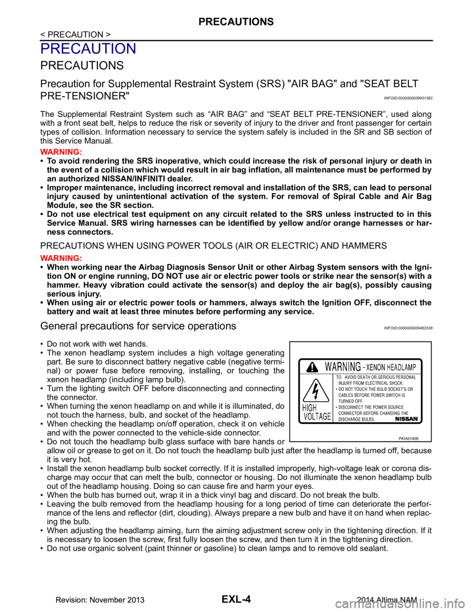
• The xenon headlamp system includes a high voltage generating
part. Be sure to disconnect batte ry negative cable (negative termi-
nal) or power fuse before removing, installing, or touching the
xenon headlamp (including lamp bulb).
• Turn the lighting switch OFF before disconnecting and connecting the connector.
• When turning the xenon headlamp on and while it is illuminated, do
not touch the harness, bulb, and socket of the headlamp.
• When checking the headlamp on/off operation, check it on vehicle and with the power connected to the vehicle-side connector.
• Do not touch the headlamp bulb glass surface with bare hands or allow oil or grease to get on it. Do not touch the headl amp bulb just after the headlamp is turned off, because
it is very hot.
• Install the xenon headlamp bulb socket co rrectly. If it is installed improperly, high-voltage leak or corona dis-
charge may occur that can melt the bulb, connector or housing. Do not illuminate the xenon headlamp bulb
out of the headlamp housing. Doing so can cause fire and harm your eyes.
• When the bulb has burned out, wrap it in a thick vinyl bag and discard. Do not break the bulb.
• Leaving the bulb removed from the headlamp housing for a long period of time can deteriorate the perfor- mance of the lens and reflector (dirt, clouding). Al ways prepare a new bulb and have it on hand when replac-
ing the bulb.
• When adjusting the headlamp aiming, turn the aiming adjus tment screw only in the tightening direction. If it
is necessary to loosen the screw, first fully loosen the screw, and then turn it in the tightening direction.
• Do not use organic solvent (paint thinner or gasoline) to clean lamps and to remove old sealant.
PKIA0183E
Revision: November 20132014 Altima NAMRevision: November 20132014 Altima NAM
Page 2529 of 4801

GI-1
GENERAL INFORMATION
C
D E
F
G H
I
J
K L
M B
GI
SECTION GI
N
O P
CONTENTS
GENERAL INFORMATION
HOW TO USE THIS MANU AL ......................3
HOW TO USE THIS MANUAL ....................... .....3
Description .......................................................... ......3
Terms ........................................................................3
Units ..........................................................................3
Contents ....................................................................3
Relation between Illustrations and Descriptions .......4
Components ..............................................................4
HOW TO FOLLOW TROUBLE DIAGNOSES .....6
Description ................................................................6
How to Follow Test Groups in Trouble Diagnosis ......6
Key to Symbols Signifying Measurements or Pro-
cedures ............................................................... ......
7
HOW TO READ WIRING DIAGRAMS ................9
Connector symbols ............................................. ......9
Sample/wiring diagram -example- ...........................10
Description ..............................................................11
ABBREVIATIONS .......................................... ....13
Abbreviation List .................................................. ....13
TIGHTENING TORQUE OF STANDARD
BOLTS ............................................................ ....
18
Description .......................................................... ....18
Tightening Torque Table (New Standard Includ-
ed) ....................................................................... ....
18
RECOMMENDED CHEMICAL PRODUCTS
AND SEALANTS ............................................ ....
21
Recommended Chemical Products and Sealants ....21
VEHICLE INFORMATION ............................22
IDENTIFICATION INFORMATION ................. ....22
Model Variation ................................................... ....22
Identification Number ..............................................23
Identification Plate ...................................................24
Engine Serial Number .............................................24
CVT Number ...........................................................25
Dimensions .......................................................... ....25
Wheels & Tires ........................................................25
PRECAUTION ..............................................26
PRECAUTIONS .................................................26
Description ........................................................... ....26
Precaution for Supplemental Restraint System
(SRS) "AIR BAG" and "SEAT BELT PRE-TEN-
SIONER" ............................................................. ....
26
Precautions For Xenon Headlamp Service .............26
Procedures without Cowl Top Cover .......................27
Cautions in Removing Battery Terminal and AV
Control Unit .......................................................... ....
27
General Precautions ................................................27
Three Way Catalyst .................................................29
Fuel (Regular Unleaded Gasoline Recommend-
ed) QR25DE ........................................................ ....
29
Fuel (Regular Unleaded Gasoline Recommend-
ed) VQ35DE ........................................................ ....
29
Multiport Fuel Injection System or Engine Control
System ................................................................. ....
29
Hoses ......................................................................29
Engine Oils ..............................................................30
Air Conditioning .......................................................31
LIFTING POINT .................................................32
Special Service Tool ................................................32
Pantograph Jack ......................................................32
Garage Jack and Safety Stand ................................33
2-Pole Lift ................................................................34
Board-on Lift ............................................................35
TOW TRUCK TOWING .....................................36
Tow Truck Towing ...................................................36
Vehicle Recovery (Freeing a Stuck Vehicle) ...........36
WIRING DIAGRAM ......................................38
CONSULT CHECKING SYSTEM .....................38
Wiring Diagram .................................................... ....38
Revision: November 20132014 Altima NAMRevision: November 20132014 Altima NAM
Page 2568 of 4801
GI-40
< BASIC INSPECTION >
SERVICE INFORMATION FOR ELECTRICAL INCIDENT
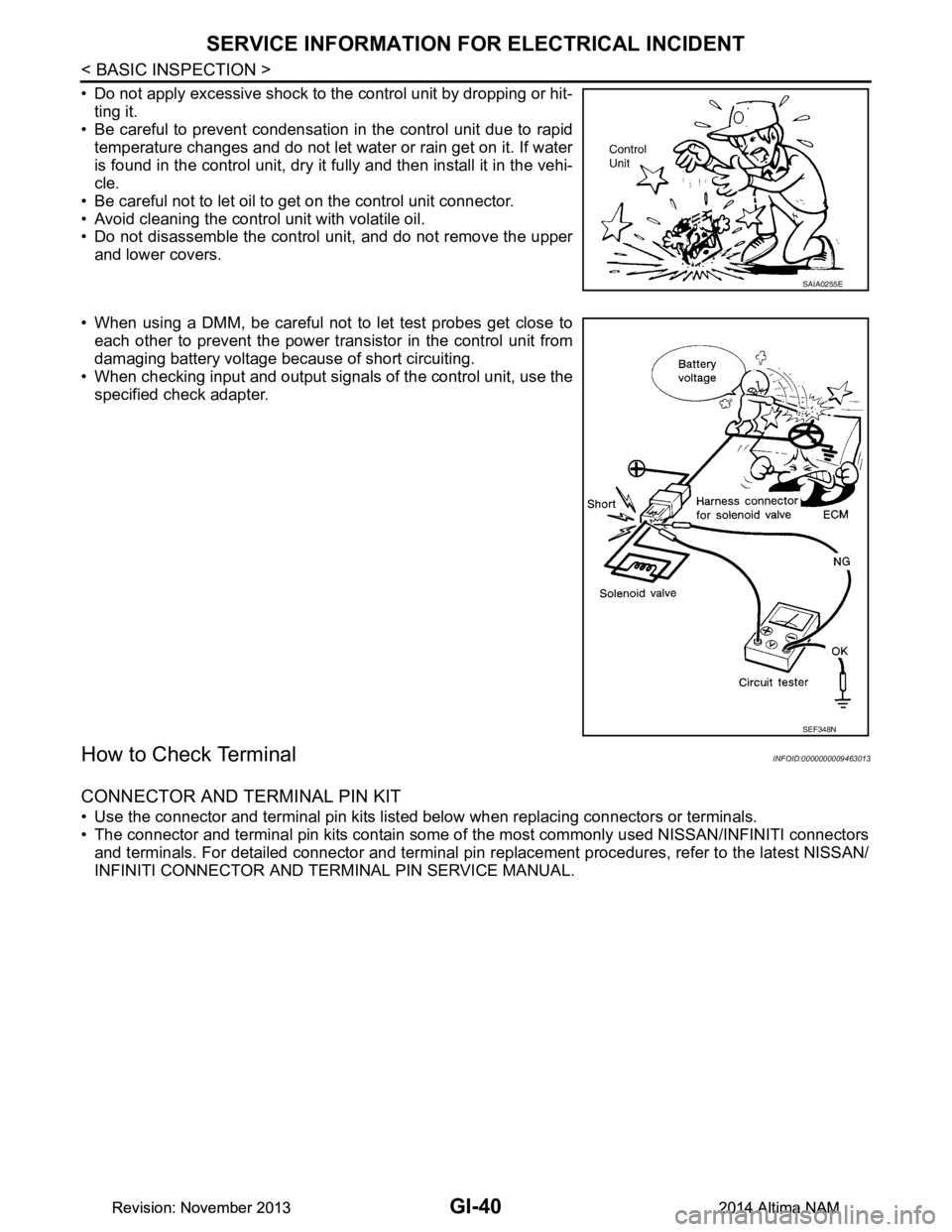
• Do not apply excessive shock to the control unit by dropping or hit-ting it.
• Be careful to prevent condensation in the control unit due to rapid
temperature changes and do not let water or rain get on it. If water
is found in the control unit, dry it fully and then install it in the vehi-
cle.
• Be careful not to let oil to get on the control unit connector.
• Avoid cleaning the control unit with volatile oil.
• Do not disassemble the control unit, and do not remove the upper
and lower covers.
• When using a DMM, be careful not to let test probes get close to each other to prevent the power tr ansistor in the control unit from
damaging battery voltage because of short circuiting.
• When checking input and output signals of the control unit, use the
specified check adapter.
How to Check TerminalINFOID:0000000009463013
CONNECTOR AND TERMINAL PIN KIT
• Use the connector and terminal pin kits listed below when replacing connectors or terminals.
• The connector and terminal pin kits contain some of the most commonly used NISSAN/INFINITI connectors
and terminals. For detailed connector and terminal pin r eplacement procedures, refer to the latest NISSAN/
INFINITI CONNECTOR AND TERMINAL PIN SERVICE MANUAL.
SAIA0255E
SEF348N
Revision: November 20132014 Altima NAMRevision: November 20132014 Altima NAM