oil temperature NISSAN TEANA 2014 User Guide
[x] Cancel search | Manufacturer: NISSAN, Model Year: 2014, Model line: TEANA, Model: NISSAN TEANA 2014Pages: 4801, PDF Size: 51.2 MB
Page 1029 of 4801
COMPONENT PARTSEC-29
< SYSTEM DESCRIPTION > [QR25DE]
C
D E
F
G H
I
J
K L
M A
EC
NP
O
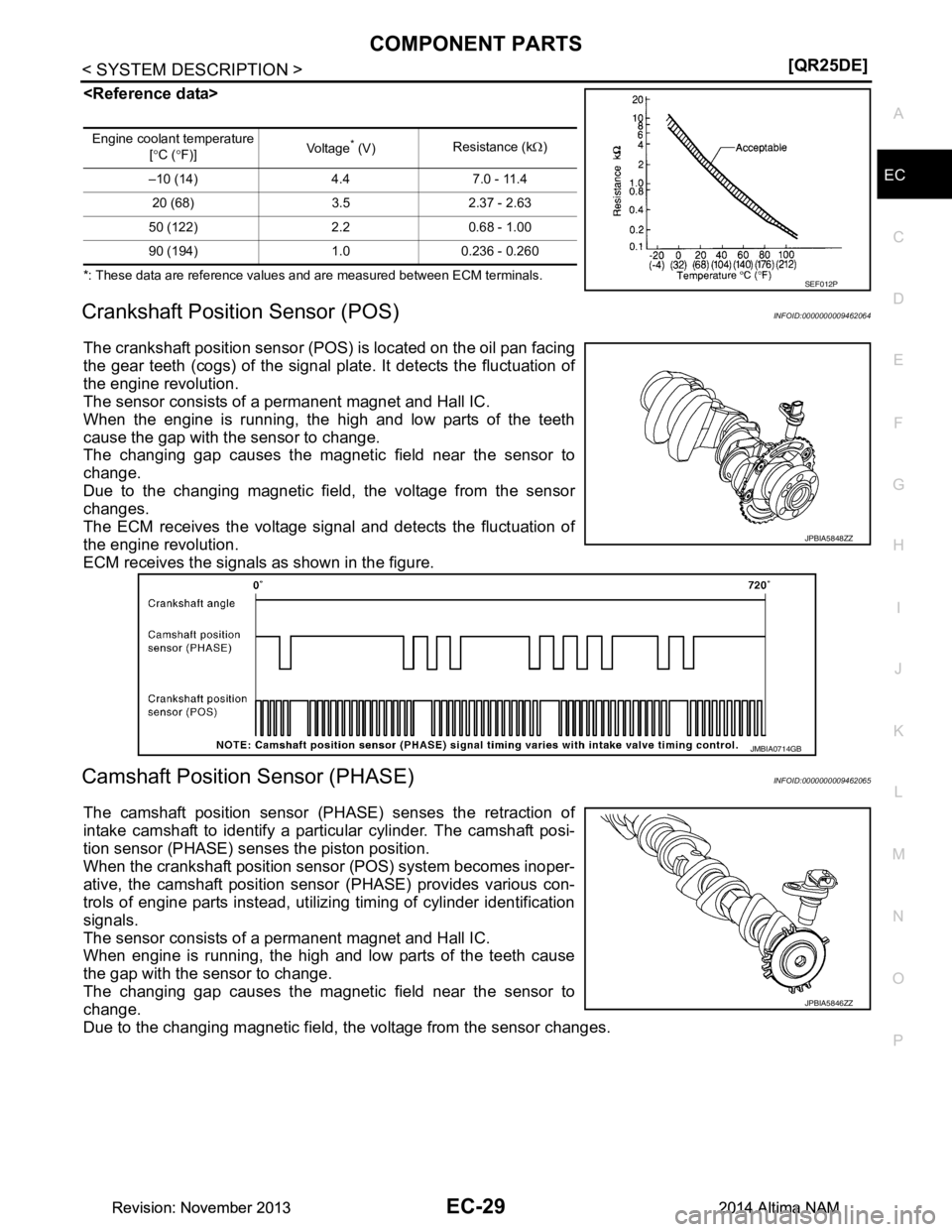
*: These data are reference values and are measured between ECM terminals.
Crankshaft Position Sensor (POS)INFOID:0000000009462064
The crankshaft position sensor (POS
) is located on the oil pan facing
the gear teeth (cogs) of the signal pl ate. It detects the fluctuation of
the engine revolution.
The sensor consists of a permanent magnet and Hall IC.
When the engine is running, the high and low parts of the teeth
cause the gap with the sensor to change.
The changing gap causes the magnet ic field near the sensor to
change.
Due to the changing magnetic fiel d, the voltage from the sensor
changes.
The ECM receives the voltage signal and detects the fluctuation of
the engine revolution.
ECM receives the signals as shown in the figure.
Camshaft Position Sensor (PHASE)INFOID:0000000009462065
The camshaft position sensor (PHASE) senses the retraction of
intake camshaft to identify a particular cylinder. The camshaft posi-
tion sensor (PHASE) senses the piston position.
When the crankshaft position sensor (POS) system becomes inoper-
ative, the camshaft position sensor (PHASE) provides various con-
trols of engine parts instead, utilizing timing of cylinder identification
signals.
The sensor consists of a permanent magnet and Hall IC.
When engine is running, the high and low parts of the teeth cause
the gap with the sensor to change.
The changing gap causes the magnet ic field near the sensor to
change.
Due to the changing magnetic field, the voltage from the sensor changes.
Engine coolant temperature
[° C ( °F)] Vo l ta g e* (V)
Resistance (k
Ω)
–10 (14) 4.4 7.0 - 11.4 20 (68) 3.5 2.37 - 2.63
50 (122) 2.2 0.68 - 1.00
90 (194) 1.0 0.236 - 0.260
SEF012P
JPBIA5848ZZ
JMBIA0714GB
JPBIA5846ZZ
Revision: November 20132014 Altima NAMRevision: November 20132014 Altima NAM
Page 1031 of 4801
COMPONENT PARTSEC-31
< SYSTEM DESCRIPTION > [QR25DE]
C
D E
F
G H
I
J
K L
M A
EC
NP
O
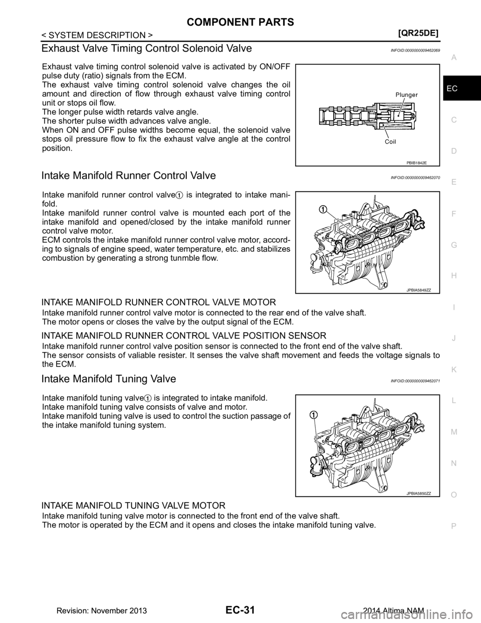
Exhaust Valve Timing Control Solenoid ValveINFOID:0000000009462069
Exhaust valve timing control solenoi
d valve is activated by ON/OFF
pulse duty (ratio) signals from the ECM.
The exhaust valve timing control solenoid valve changes the oil
amount and direction of flow through exhaust valve timing control
unit or stops oil flow.
The longer pulse width retards valve angle.
The shorter pulse width advances valve angle.
When ON and OFF pulse widths become equal, the solenoid valve
stops oil pressure flow to fix t he exhaust valve angle at the control
position.
Intake Manifold Runner Control ValveINFOID:0000000009462070
Intake manifold runner control valve is integrated to intake mani-
fold.
Intake manifold runner control valve is mounted each port of the
intake manifold and opened/closed by the intake manifold runner
control valve motor.
ECM controls the intake manifold runner control valve motor, accord-
ing to signals of engine speed, water temperature, etc. and stabilizes
combustion by generating a strong tunmble flow.
INTAKE MANIFOLD RUNNER CONTROL VALVE MOTOR
Intake manifold runner control valve motor is connected to the rear end of the valve shaft.
The motor opens or closes the valve by the output signal of the ECM.
INTAKE MANIFOLD RUNNER CONTROL VALVE POSITION SENSOR
Intake manifold runner control valve position sensor is connected to the front end of the valve shaft.
The sensor consists of valiable resister. It senses the valve shaft movement and feeds the voltage signals to
the ECM.
Intake Manifold Tuning ValveINFOID:0000000009462071
Intake manifold tuning valve is integrated to intake manifold.
Intake manifold tuning valve consists of valve and motor.
Intake manifold tuning valve is used to control the suction passage of
the intake manifold tuning system.
INTAKE MANIFOLD TUNING VALVE MOTOR
Intake manifold tuning valve motor is connected to the front end of the valve shaft.
The motor is operated by the ECM and it opens a nd closes the intake manifold tuning valve.
PBIB1842E
JPBIA5849ZZ
JPBIA5850ZZ
Revision: November 20132014 Altima NAMRevision: November 20132014 Altima NAM
Page 1033 of 4801
COMPONENT PARTSEC-33
< SYSTEM DESCRIPTION > [QR25DE]
C
D E
F
G H
I
J
K L
M A
EC
NP
O
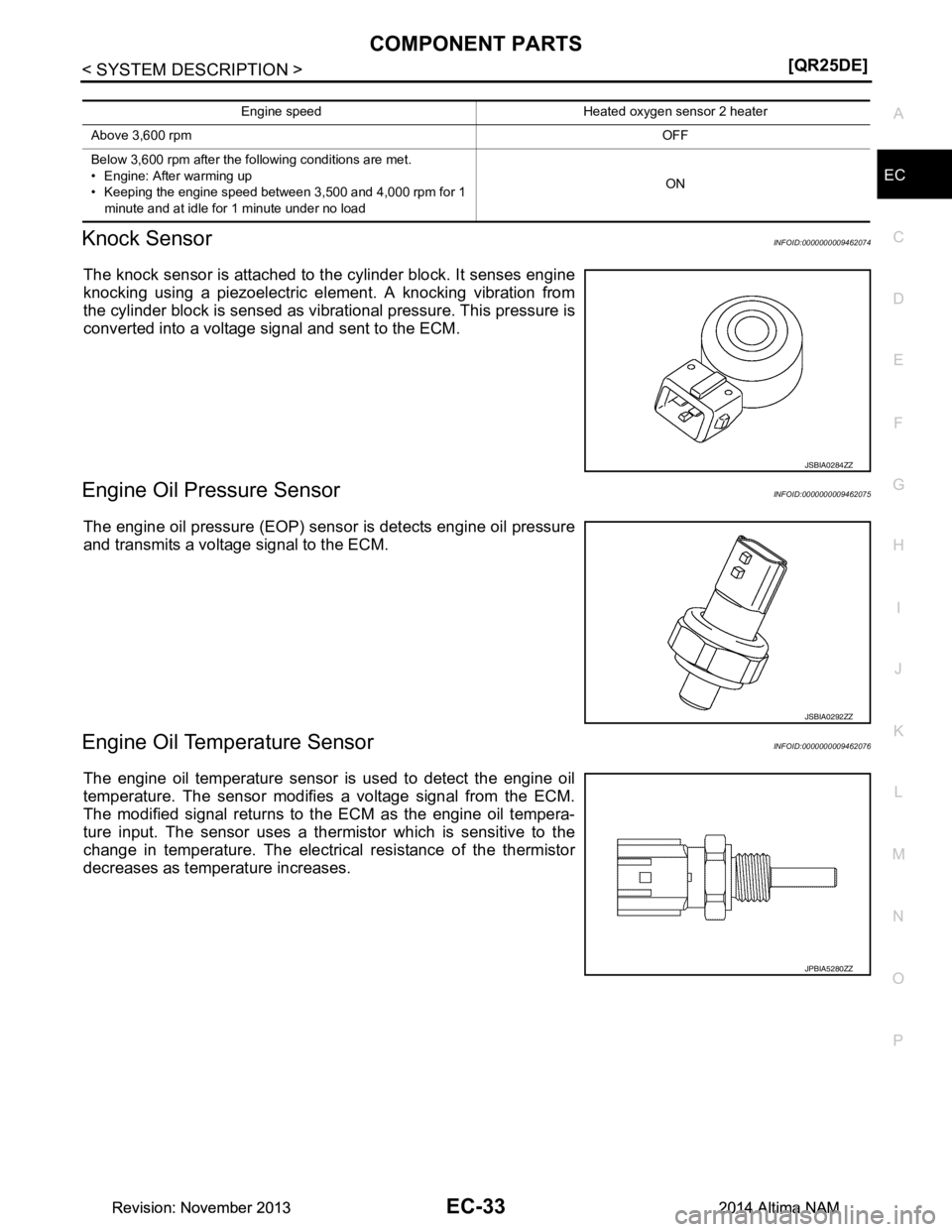
Knock SensorINFOID:0000000009462074
The knock sensor is attached to t
he cylinder block. It senses engine
knocking using a piezoelectric el ement. A knocking vibration from
the cylinder block is sensed as vibrational pressure. This pressure is
converted into a voltage signal and sent to the ECM.
Engine Oil Pressure SensorINFOID:0000000009462075
The engine oil pressure (EOP) sens or is detects engine oil pressure
and transmits a voltage signal to the ECM.
Engine Oil Temperature SensorINFOID:0000000009462076
The engine oil temperature sensor is used to detect the engine oil
temperature. The sensor modifies a voltage signal from the ECM.
The modified signal returns to the ECM as the engine oil tempera-
ture input. The sensor uses a ther mistor which is sensitive to the
change in temperature. The electrical resistance of the thermistor
decreases as temperature increases.
Engine speed Heated oxygen sensor 2 heater
Above 3,600 rpm OFF
Below 3,600 rpm after the following conditions are met.
• Engine: After warming up
• Keeping the engine speed between 3,500 and 4,000 rpm for 1
minute and at idle for 1 minute under no load ON
JSBIA0284ZZ
JSBIA0292ZZ
JPBIA5280ZZ
Revision: November 20132014 Altima NAMRevision: November 20132014 Altima NAM
Page 1034 of 4801
EC-34
< SYSTEM DESCRIPTION >[QR25DE]
COMPONENT PARTS
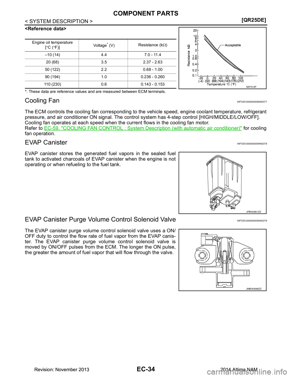
*: These data are reference values and are measured between ECM terminals.
Cooling FanINFOID:0000000009462077
The ECM controls the cooling fan corresponding to the
vehicle speed, engine coolant temperature, refrigerant
pressure, and air conditioner ON signal. The control system has 4-step control [HIGH/MIDDLE/LOW/OFF].
Cooling fan operates at each speed when the current flows in the cooling fan motor.
Refer to EC-59, "COOLING FAN CONTROL : System De scription (with automatic air conditioner)"
for cooling
fan operation.
EVAP CanisterINFOID:0000000009462078
EVAP canister stores the generat ed fuel vapors in the sealed fuel
tank to activated charcoals of EVAP canister when the engine is not
operating or when refueling to the fuel tank.
EVAP Canister Purge Volume Control Solenoid ValveINFOID:0000000009462079
The EVAP canister purge volume control solenoid valve uses a ON/
OFF duty to control the flow rate of fuel vapor from the EVAP canis-
ter. The EVAP canister purge volume control solenoid valve is
moved by ON/OFF pulses from the ECM. The longer the ON pulse,
the greater the amount of fuel vapor that will flow through the valve.
Engine oil temperature
[° C ( °F)] Vol tag e* (V)
Resistance (k
Ω)
–10 (14) 4.4 7.0 - 11.4 20 (68) 3.5 2.37 - 2.63
50 (122) 2.2 0.68 - 1.00
90 (194) 1.0 0.236 - 0.260
110 (230) 0.6 0.143 - 0.153
SEF012P
JPBIA5851ZZ
JMBIA0069ZZ
Revision: November 20132014 Altima NAMRevision: November 20132014 Altima NAM
Page 1035 of 4801
COMPONENT PARTSEC-35
< SYSTEM DESCRIPTION > [QR25DE]
C
D E
F
G H
I
J
K L
M A
EC
NP
O
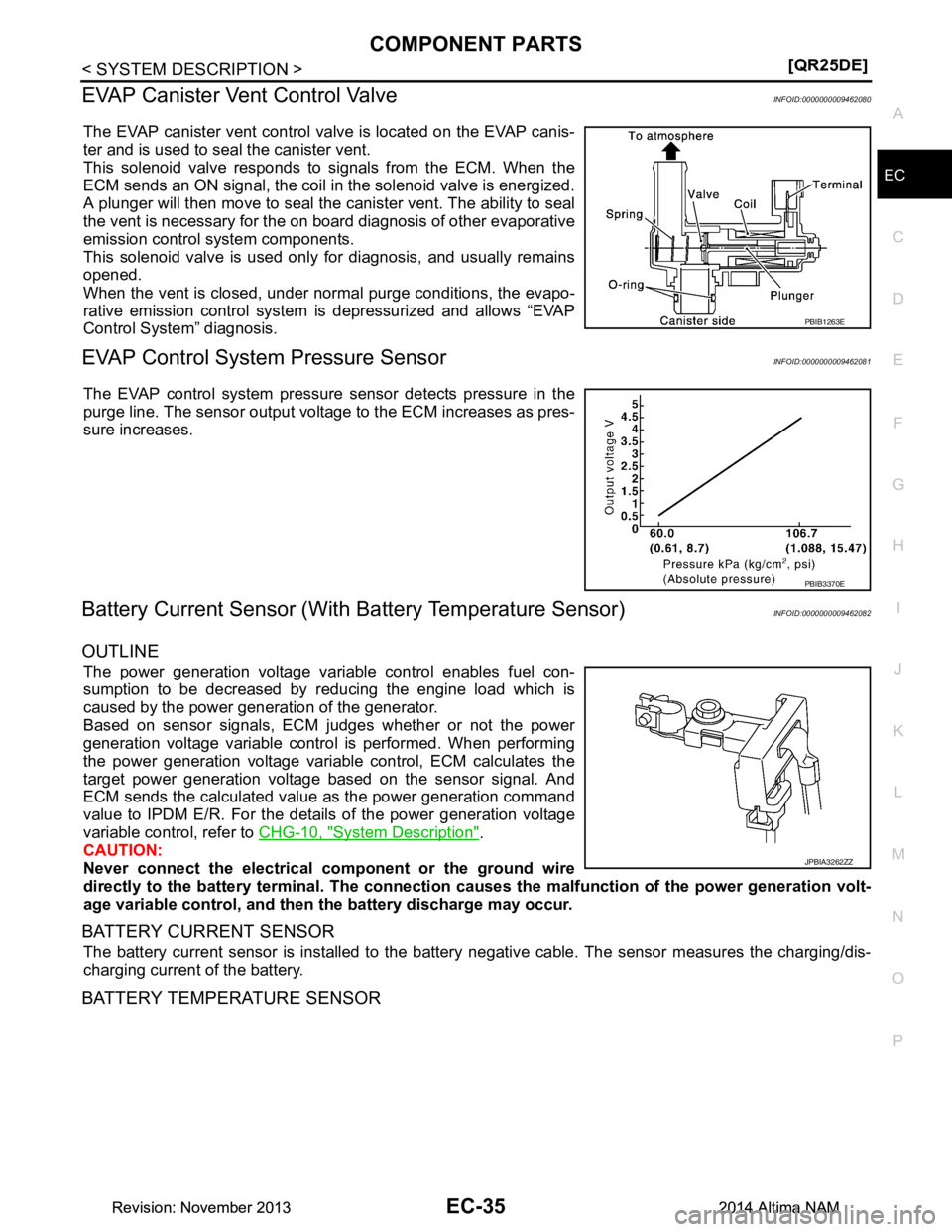
EVAP Canister Vent Control ValveINFOID:0000000009462080
The EVAP canister vent control valve is located on the EVAP canis-
ter and is used to seal the canister vent.
This solenoid valve responds to signals from the ECM. When the
ECM sends an ON signal, the coil in the solenoid valve is energized.
A plunger will then move to seal the canister vent. The ability to seal
the vent is necessary for the on board diagnosis of other evaporative
emission control system components.
This solenoid valve is used only for diagnosis, and usually remains
opened.
When the vent is closed, under normal purge conditions, the evapo-
rative emission control system is depressurized and allows “EVAP
Control System” diagnosis.
EVAP Control System Pressure SensorINFOID:0000000009462081
The EVAP control system pressure sensor detects pressure in the
purge line. The sensor output voltage to the ECM increases as pres-
sure increases.
Battery Current Sensor (With Battery Temperature Sensor)INFOID:0000000009462082
OUTLINE
The power generation voltage variable control enables fuel con-
sumption to be decreased by reducing the engine load which is
caused by the power generation of the generator.
Based on sensor signals, ECM judges whether or not the power
generation voltage variable contro l is performed. When performing
the power generation voltage variable control, ECM calculates the
target power generation voltage based on the sensor signal. And
ECM sends the calculated value as the power generation command
value to IPDM E/R. For the details of the power generation voltage
variable control, refer to CHG-10, "System Description"
.
CAUTION:
Never connect the electrical co mponent or the ground wire
directly to the battery terminal. The connection cau ses the malfunction of the power generation volt-
age variable control, and then the battery discharge may occur.
BATTERY CURRENT SENSOR
The battery current sensor is installed to the battery negative cable. The sensor measures the charging/dis-
charging current of the battery.
BATTERY TEMPERATURE SENSOR
PBIB1263E
PBIB3370E
JPBIA3262ZZ
Revision: November 20132014 Altima NAMRevision: November 20132014 Altima NAM
Page 1036 of 4801
EC-36
< SYSTEM DESCRIPTION >[QR25DE]
COMPONENT PARTS
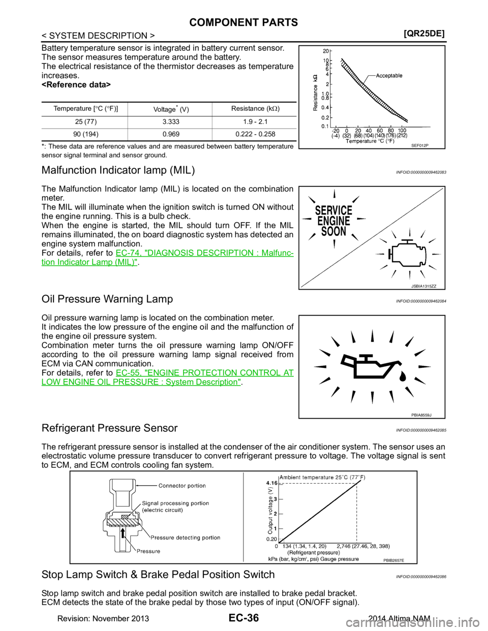
Battery temperature sensor is int
egrated in battery current sensor.
The sensor measures temperature around the battery.
The electrical resistance of the t hermistor decreases as temperature
increases.
*: These data are reference values and are measured between battery temperature
sensor signal terminal and sensor ground.
Malfunction Indicator lamp (MIL)INFOID:0000000009462083
The Malfunction Indicator lamp (MIL) is located on the combination
meter.
The MIL will illuminate when the ignition switch is turned ON without
the engine running. This is a bulb check.
When the engine is started, the MI L should turn OFF. If the MIL
remains illuminated, the on board diagnostic system has detected an
engine system malfunction.
For details, refer to EC-74, "DIAGNOSIS DESCRIPTION : Malfunc-
tion Indicator Lamp (MIL)".
Oil Pressure Warning LampINFOID:0000000009462084
Oil pressure warning lamp is located on the combination meter.
It indicates the low pressure of the engine oil and the malfunction of
the engine oil pressure system.
Combination meter turns the oil pressure warning lamp ON/OFF
according to the oil pressure warning lamp signal received from
ECM via CAN communication.
For details, refer to EC-55, "ENGINE PROTECTION CONTROL AT
LOW ENGINE OIL PRESSURE : System Description".
Refrigerant Pressure SensorINFOID:0000000009462085
The refrigerant pressure sensor is installed at the c ondenser of the air conditioner system. The sensor uses an
electrostatic volume pressure transducer to convert refrigerant pressure to voltage. The voltage signal is sent
to ECM, and ECM controls cooling fan system.
Stop Lamp Switch & Brake Pedal Position SwitchINFOID:0000000009462086
Stop lamp switch and brake pedal position switch are installed to brake pedal bracket.
ECM detects the state of the brake pedal by those two types of input (ON/OFF signal).
Temperature [°C ( °F)]
Vo l ta g e* (V) Resistance (k
Ω)
25 (77) 3.333 1.9 - 2.1
90 (194) 0.969 0.222 - 0.258
SEF012P
JSBIA1315ZZ
PBIA8559J
PBIB2657E
Revision: November 20132014 Altima NAMRevision: November 20132014 Altima NAM
Page 1042 of 4801
EC-42
< SYSTEM DESCRIPTION >[QR25DE]
SYSTEM
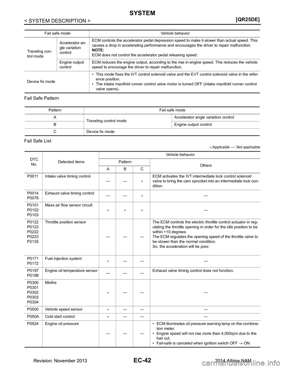
Fail Safe Pattern
Fail Safe List
× :Applicable —: Not applicable
Fail safe mode Vehicle behavior
Traveling con-
trol mode Accelerator an-
gle variation
control ECM controls the accelerator pedal depression speed to make it slower than actual speed. This
causes a drop in accelerating performance and encourages the driver to repair malfunction.
NOTE:
ECM does not control the accelerator pedal releasing speed.
Engine output
control ECM reduces the engine output, according to the rise in engine speed. This reduces the vehicle
speed to encourage the driver to repair malfunction.
Device fix mode • This mode fixes the IVT control solenoid valve and the EVT control solenoid valve in the refer-
ence position.
• The intake manifold runner control valve motor is turned OFF (intake manifold runner control valve opens).
Pattern Fail safe mode
A Traveling control mode Accelerator angle variation control
B Engine output control
C Device fix mode
DTC No. Detected items Vehicle behavior
Pattern Others
ABC
P0011 Intake valve timing control ——×ECM activates the IVT intermediate lock control solenoid
valve to bring the cam sprocket into an intermediate lock con-
dition.
P0014
P0078 Exhaust valve timing control
——× —
P0101
P0102
P0103 Mass air flow sensor circuit
××× —
P0122
P0123
P0222
P0223
P2135 Throttle position sensor
———The ECM controls the electric throttle control actuator in reg-
ulating the throttle opening in order for the idle position to be
within +10 degrees.
The ECM regulates the opening speed of the throttle valve to
be slower than the normal condition.
So, the acceleration will be poor.
P0171
P0172 Fuel injection system
×—— —
P0197
P0198 Engine oil temperature sensor
———Exhaust valve timing control does not function.
P0300
P0301
P0302
P0303
P0304 Misfire
×—— —
P0500 Vehicle speed sensor ×—— —
P050A Cold start control ×—— —
P0524 Engine oil pressure
———• ECM illuminates oil pressure warning lamp on the combina-
tion meter.
• Engine speed will not rise more than 4,000rpm due to the
fuel cut.
• Fail-safe is canceled when ignition switch OFF → ON.
Revision: November 20132014 Altima NAMRevision: November 20132014 Altima NAM
Page 1049 of 4801
SYSTEMEC-49
< SYSTEM DESCRIPTION > [QR25DE]
C
D E
F
G H
I
J
K L
M A
EC
NP
O
The ECM receives information such as the injecti
on pulse width and camshaft position sensor (PHASE) sig-
nal. Computing this information, ignition si gnals are transmitted to the power transistor.
During the following conditions, the ignition timing is revi sed by the ECM according to the other data stored in
the ECM.
• At starting
• During warm-up
•At idle
• At low battery voltage
• During acceleration
The knock sensor retard system is designed only for emergencies. The basic ignition timing is programmed
within the anti-knocking zone, if recommended fuel is used under dry conditions. The retard system does not
operate under normal driving conditions. If engine knocking occurs, the knock sensor monitors the condition.
The signal is transmitted to the ECM. The ECM retards the ignition timing to eliminate the knocking condition.
INTAKE VALVE TIMING CONTROL
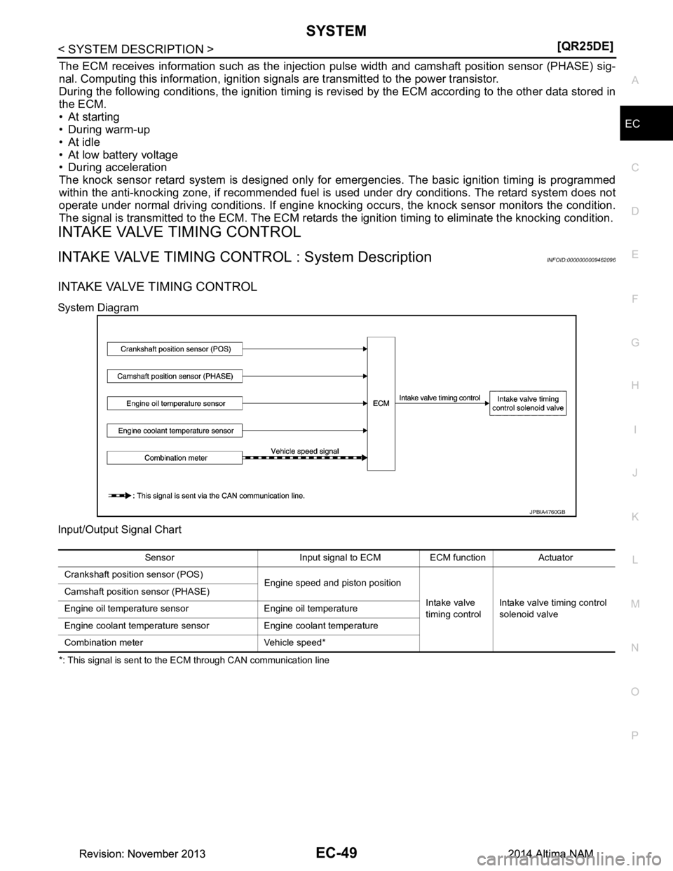
INTAKE VALVE TIMING CONTROL : System DescriptionINFOID:0000000009462096
INTAKE VALVE TIMING CONTROL
System Diagram
Input/Output Signal Chart
*: This signal is sent to the ECM through CAN communication line
JPBIA4760GB
Sensor Input signal to ECM ECM function Actuator
Crankshaft position sensor (POS) Engine speed and piston position
Intake valve
timing control Intake valve timing control
solenoid valve
Camshaft position sensor (PHASE)
Engine oil temperature sensor Engine oil temperature
Engine coolant temperature sensor Engine coolant temperature
Combination meter Vehicle speed*
Revision: November 20132014 Altima NAMRevision: November 20132014 Altima NAM
Page 1052 of 4801
EC-52
< SYSTEM DESCRIPTION >[QR25DE]
SYSTEM
When starting the engine by cold start, ECM judges the
locked/unlocked state when ignition switch is turned
ON. When judged as locked state (fixed at the intermedi ate phase), the intake valve timing intermediate lock
control solenoid valve is activated. Since oil pre ssure does not act on the lock key even when the engine is
started, the cam phase is fixed at the intermediate phas e and the intake valve timing control is not performed.
When the engine stops without locking the cam phase at the intermediate phase due to an engine stall and the
state is not judged as locked, the intake valve timing intermediate lock control solenoid valve and the intake
valve timing control solenoid valve are activated and the cam phase shifts to the advanced position to be
locked at the intermediate phase. Even when not locked in the intermediate lock phase due to no oil pressure
or low oil pressure, a ratchet structure of the camshaft sprocket (INT) rotor allows the conversion to the inter-
mediate phase in stages by engine vibration.
When engine coolant temperature is more than 60 °C, the intake valve timing is controlled by deactivating the
intake valve timing intermediate lock control so lenoid valve and releasing the intermediate phase lock.
When the engine is started after warming up, ECM releas es the intermediate phase lock immediately after the
engine start and controls the intake valve timing.
EXHAUST VALVE TIMING CONTROL
EXHAUST VALVE TIMING CONT ROL : System DescriptionINFOID:0000000009462097
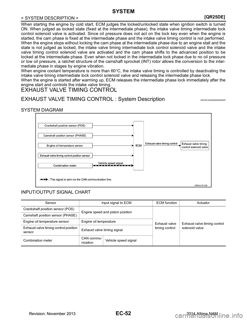
SYSTEM DIAGRAM
INPUT/OUTPUT SIGNAL CHART
JPBIA4761GB
Sensor Input signal to ECM ECM function Actuator
Crankshaft position sensor (POS) Engine speed and piston position
Exhaust valve
timing control Exhaust valve timing control
solenoid valve
Camshaft position sensor (PHASE)
Engine oil temperature sensor Engine oil temperature
Exhaust valve timing control position
sensor Exhaust valve timing signal
Combination meter CAN commu-
nication Vehicle speed signal
Revision: November 20132014 Altima NAMRevision: November 20132014 Altima NAM
Page 1053 of 4801
SYSTEMEC-53
< SYSTEM DESCRIPTION > [QR25DE]
C
D E
F
G H
I
J
K L
M A
EC
NP
O
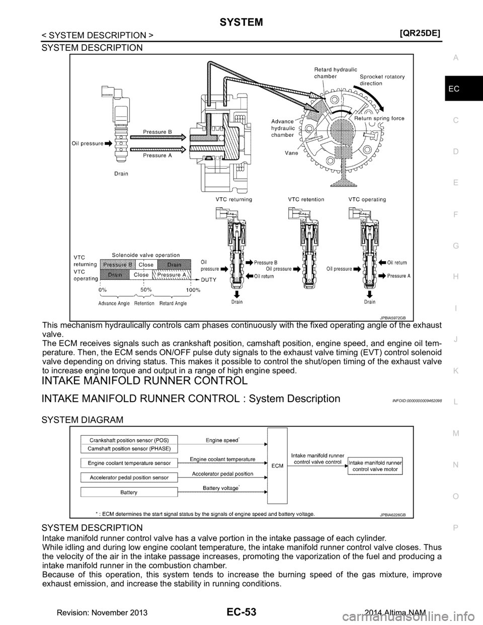
SYSTEM DESCRIPTION
This mechanism hydraulically controls cam phases c
ontinuously with the fixed operating angle of the exhaust
valve.
The ECM receives signals such as crankshaft position, camshaft position, engine speed, and engine oil tem-
perature. Then, the ECM sends ON/OFF pulse duty signal s to the exhaust valve timing (EVT) control solenoid
valve depending on driving status. This makes it possible to control the shut/open timing of the exhaust valve
to increase engine torque and output in a range of high engine speed.
INTAKE MANIFOLD RUNNER CONTROL
INTAKE MANIFOLD RUNNER CONTROL : System DescriptionINFOID:0000000009462098
SYSTEM DIAGRAM
SYSTEM DESCRIPTION
Intake manifold runner control valve has a valve portion in the intake passage of each cylinder.
While idling and during low engine coolant temperature, t he intake manifold runner control valve closes. Thus
the velocity of the air in the intake passage increases , promoting the vaporization of the fuel and producing a
intake manifold runner in the combustion chamber.
Because of this operation, this system tends to in crease the burning speed of the gas mixture, improve
exhaust emission, and increase the stability in running conditions.
JPBIA5972GB
JPBIA6226GB
Revision: November 20132014 Altima NAMRevision: November 20132014 Altima NAM