oil temperature NISSAN TEANA 2014 Service Manual
[x] Cancel search | Manufacturer: NISSAN, Model Year: 2014, Model line: TEANA, Model: NISSAN TEANA 2014Pages: 4801, PDF Size: 51.2 MB
Page 4456 of 4801
SYSTEMTM-241
< SYSTEM DESCRIPTION > [CVT: RE0F10E]
C
EF
G H
I
J
K L
M A
B
TM
N
O P
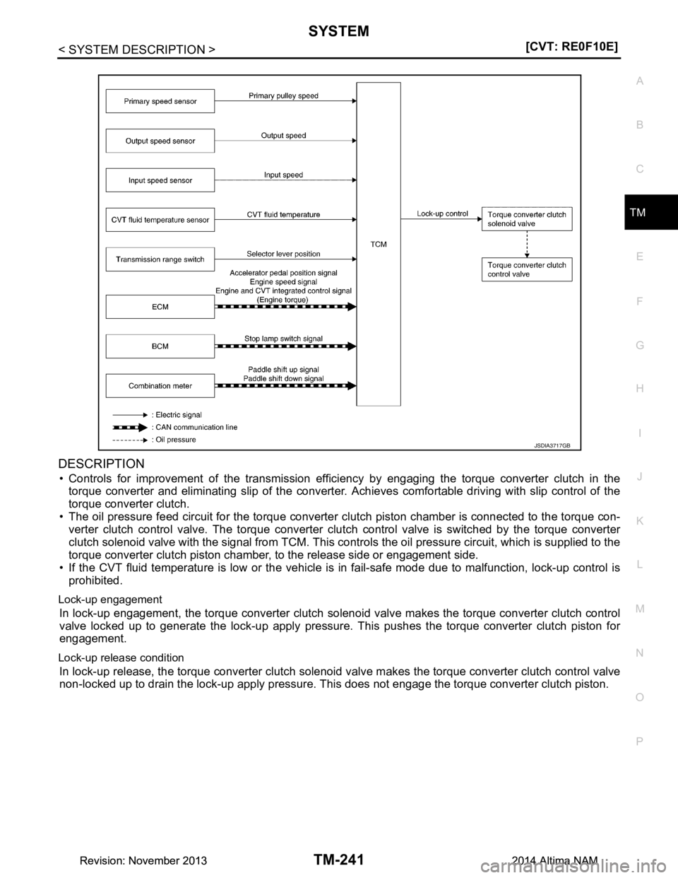
DESCRIPTION
• Controls for improvement of the transmission effici ency by engaging the torque converter clutch in the
torque converter and eliminating slip of the converter. Achieves comfortable driving with slip control of the
torque converter clutch.
• The oil pressure feed circuit for the torque converter clutch piston chamber is connected to the torque con-
verter clutch control valve. The torque converter clut ch control valve is switched by the torque converter
clutch solenoid valve with the signal from TCM. This contro ls the oil pressure circuit, which is supplied to the
torque converter clutch piston chamber, to the release side or engagement side.
• If the CVT fluid temperature is low or the vehicle is in fail-safe mode due to malfunction, lock-up control is
prohibited.
Lock-up engagement
In lock-up engagement, the torque converter clutch solenoi d valve makes the torque converter clutch control
valve locked up to generate the lock-up apply pressure. This pushes the torque converter clutch piston for
engagement.
Lock-up release condition
In lock-up release, the torque converter clutch solenoi d valve makes the torque converter clutch control valve
non-locked up to drain the lock-up apply pressure. This does not engage the torque converter clutch piston.
JSDIA3717GB
Revision: November 20132014 Altima NAMRevision: November 20132014 Altima NAM
Page 4462 of 4801
DIAGNOSIS SYSTEM (TCM)TM-247
< SYSTEM DESCRIPTION > [CVT: RE0F10E]
C
EF
G H
I
J
K L
M A
B
TM
N
O P
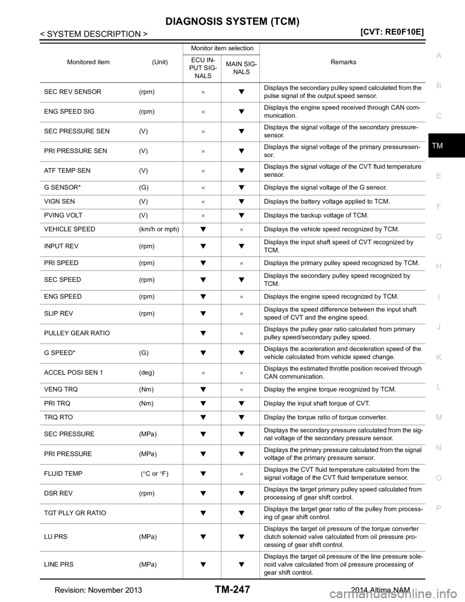
SEC REV SENSOR (rpm) ×Displays the secondary pulley speed calculated from the
pulse signal of the output speed sensor.
ENG SPEED SIG (rpm) ×Displays the engine speed received through CAN com-
munication.
SEC PRESSURE SEN (V) ×Displays the signal voltage of the secondary pressure-
sensor.
PRI PRESSURE SEN (V) ×Displays the signal voltage of the primary pressuresen-
sor.
ATF TEMP SEN (V) ×Displays the signal voltage of the CVT fluid temperature
sensor.
G SENSOR* (G) ×Displays the signal voltage of the G sensor.
VIGN SEN (V) ×Displays the battery voltage applied to TCM.
PVING VOLT (V) ×Displays the backup voltage of TCM.
VEHICLE SPEED (km/h or mph) ×Displays the vehicle speed recognized by TCM.
INPUT REV (rpm) Displays the input shaft speed of CVT recognized by
TCM.
PRI SPEED (rpm) ×Displays the primary pulley speed recognized by TCM.
SEC SPEED (rpm) Displays the secondary pulley speed recognized by
TCM.
ENG SPEED (rpm) ×Displays the engine speed recognized by TCM.
SLIP REV (rpm) ×Displays the speed difference between the input shaft
speed of CVT and the engine speed.
PULLEY GEAR RATIO ×Displays the pulley gear ratio calculated from primary
pulley speed/secondary pulley speed.
G SPEED* (G) Displays the acceleration and deceleration speed of the
vehicle calculated from vehicle speed change.
ACCEL POSI SEN 1 (deg) ××Displays the estimated throttle position received through
CAN communication.
VENG TRQ (Nm) ×Display the engine torque recognized by TCM.
PRI TRQ (Nm) Display the input shaft torque of CVT.
TRQ RTO Display the torque ratio of torque converter.
SEC PRESSURE (MPa) Displays the secondary pressure calculated from the sig-
nal voltage of the secondary pressure sensor.
PRI PRESSURE (MPa) Displays the primary pressure calculated from the signal
voltage of the primary pressure sensor.
FLUID TEMP ( °C or °F) ×Displays the CVT fluid temperature calculated from the
signal voltage of the CVT fluid temperature sensor.
DSR REV (rpm) Displays the target primary pulley speed calculated from
processing of gear shift control.
TGT PLLY GR RATIO Displays the target gear ratio of the pulley from process-
ing of gear shift control.
LU PRS (MPa) Displays the target oil pressure of the torque converter
clutch solenoid valve calculated from oil pressure pro-
cessing of gear shift control.
LINE PRS (MPa) Displays the target oil pressure of the line pressure sole-
noid valve calculated from oil pressure processing of
gear shift control.
Monitored item (Unit)
Monitor item selection
Remarks
ECU IN-
PUT SIG-
NALS MAIN SIG-
NALS
Revision: November 20132014 Altima NAMRevision: November 20132014 Altima NAM
Page 4476 of 4801
TCM
TM-261
< ECU DIAGNOSIS INFORMATION > [CVT: RE0F10E]
C
EF
G H
I
J
K L
M A
B
TM
N
O P
Protection Control INFOID:0000000009464220
The TCM becomes the protection control status temporar ily to protect the safety when the safety of TCM and
transmission is lost. It automatically returns to the normal status if the safety is secured.
The TCM has the following protection control.
CONTROL FOR WHEEL SPIN
TORQUE IS REDUCED WHEN DRIVING WITH THE REVERSE GEAR
CONTROL WHEN FLUID TEMPERATURE IS HIGH
P2765 •Start is slow
• Acceleration is slow
• Lock-up is not performed —
P2813 • Selector shock is large
•Start is slow
• Acceleration is slow
• Vehicle speed is not increased When a malfunction occurs on the low oil pressure side
• Selector shock is large When a malfunction occurs on the high oil pressure side
P2814 • Selector shock is large —
P2815 • Selector shock is large —
U0073 • Selector shock is large
•Start is slow
• Acceleration is slow
• Lock-up is not performed —
U0100 • Selector shock is large
•Start is slow
• Acceleration is slow
• Lock-up is not performed —
U0140 • Not changed from normal driving —
U0141 • Not changed from normal driving —
U0155 • Not changed from normal driving —
U0300 • Selector shock is large
•Start is slow
• Acceleration is slow
• Lock-up is not performed —
U1000 • Not changed from normal driving — U1117 • Not changed from normal driving — DTC Vehicle behavior Conditions of vehicle
Control
When a wheel spin is detected, the engine output and gear ratio are limited and the line pressure is increased.
Limits engine output when a wheel spin occurs in any of right and left drive wheels.
Vehicle behavior in
control If the accelerator is kept depressing during wheel spin, the engine revolution and vehicle speed are limited to
a certain degree.
Normal return condi-
tion Wheel spin convergence returns the control to the normal control.
Control Engine output is controlled according to a vehicle speed while reversing the vehicle.
Vehicle behavior in
control Power performance may be lowered while reversing the vehicle.
Normal return condi-
tion Torque returns to normal by positioning the sele
ctor lever in a range other than “R” position.
Revision: November 20132014 Altima NAMRevision: November 20132014 Altima NAM
Page 4477 of 4801
TM-262
< ECU DIAGNOSIS INFORMATION >[CVT: RE0F10E]
TCM
REVERSE PROHIBIT CONTROL
DTC Inspection Priority ChartINFOID:0000000009464221
If multiple malfunction codes are detected at the same
time, check each code according to the DTC check pri-
ority list below.
Control When the CVT fluid temperature is high, the gear shift permission maximum revolution and the maximum
torque are reduced than usual to prevent increase of the oil temperature.
Vehicle behavior in
control Power performance may be lowered, compared to normal control.
Normal retu rn condi-
tion The control returns to the normal control when CVT fluid temperature is lowered.
ControlThe reverse brake is controlled to avoid becoming engaged when the selector lever is set in “R” position while
driving in forward direction at more than the specified speed.
Vehicle behavior in
control If the selector lever is put at “R” position when driving with the forward gear, the gear becomes neutral, not
reverse.
Normal retu rn condi-
tion The control returns to normal control when the vehicle is driven at low speeds. (The reverse brake becomes
engaged.)
Priority DTC (Diagnostic Trouble Code) Reference
1 P0863 CONTROL UNIT (CAN)
TM-345, "DTC Logic"
U0073 COMM BUS A OFFTM-290, "DTC Logic"
U0100 LOST COMM (ECM A)TM-291, "DTC Logic"
U0140 LOST COMM (BCM)TM-292, "DTC Logic"
U0141 LOST COMM (BCM A)TM-293, "DTC Logic"
U0155 LOST COMM (IPC)TM-294, "DTC Logic"
U0300 CAN COMM DATA TM-294, "DTC Logic"
U1000 CAN COMM CIRCTM-296, "DTC Logic"
U1117 LOST COMM (ABS)TM-297, "DTC Logic"
2P0740 TORQUE CONVERTER
TM-322, "DTC Logic"
P0743 TORQUE CONVERTERTM-324, "DTC Logic"
P0778 PC SOLENOID BTM-332, "DTC Logic"
P0779 PC SOLENOID BTM-334, "DTC Logic"
P0962 PC SOLENOID ATM-347, "DTC Logic"
P0963 PC SOLENOID ATM-349, "DTC Logic"
P0966 PC SOLENOID BTM-353, "DTC Logic"
P0967 PC SOLENOID BTM-355, "DTC Logic"
P2814 SELECT SOLENOIDTM-362, "DTC Logic"
P2815 SELECT SOLENOIDTM-364, "DTC Logic"
Revision: November 20132014 Altima NAMRevision: November 20132014 Altima NAM
Page 4500 of 4801
CVT FLUIDTM-285
< BASIC INSPECTION > [CVT: RE0F10E]
C
EF
G H
I
J
K L
M A
B
TM
N
O P
CVT FLUID
ReplacementINFOID:0000000009464231
CAUTION:
• Always use shop paper. Never use shop cloth.
• Replace a drain plug gasket with new ones at the fi nal stage of the operation when installing.
• Use caution when looking into the drain hole as there is a risk of dripping fluid entering the eye.
• After replacement, always pe rform CVT fluid leakage check.
1. Select “Data Monitor” in “TRANSMISSION” using CONSULT.
2. Select “FLUID TEMP” and confirm t hat the CVT fluid temperature is 40°C (104 °F) or less.
3. Check that the selector lever is in the “P ” position, then completely engage the parking brake.
4. Lift up the vehicle.
5. Remove the drain plug and drain the CVT fluid from the oil pan. Refer to TM-387, "Exploded View"
.
6. Install the drain plug to oil pan. CAUTION:
Drain plug gasket use the old one.
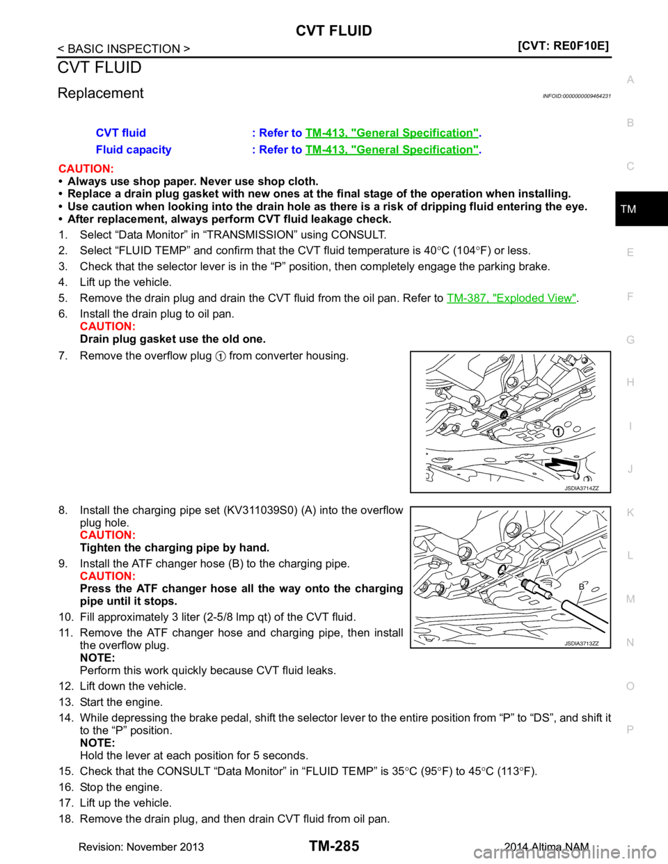
7. Remove the overflow plug from converter housing.
8. Install the charging pipe set (KV311039S0) (A) into the overflow plug hole.
CAUTION:
Tighten the charging pipe by hand.
9. Install the ATF changer hose (B) to the charging pipe. CAUTION:
Press the ATF changer hose all the way onto the charging
pipe until it stops.
10. Fill approximately 3 liter (2-5 /8 lmp qt) of the CVT fluid.
11. Remove the ATF changer hose and charging pipe, then install the overflow plug.
NOTE:
Perform this work quickly because CVT fluid leaks.
12. Lift down the vehicle.
13. Start the engine.
14. While depressing the brake pedal, shift the selector leve r to the entire position from “P” to “DS”, and shift it
to the “P” position.
NOTE:
Hold the lever at each position for 5 seconds.
15. Check that the CONSULT “Data Monitor” in “FLUID TEMP” is 35°C (95 °F) to 45 °C (113 °F).
16. Stop the engine.
17. Lift up the vehicle.
18. Remove the drain plug, and then drain CVT fluid from oil pan. CVT fluid : Refer to
TM-413, "General Specification"
.
Fluid capacity : Refer to TM-413, "General Specification"
.
JSDIA3714ZZ
JSDIA3713ZZ
Revision: November 20132014 Altima NAMRevision: November 20132014 Altima NAM
Page 4501 of 4801
TM-286
< BASIC INSPECTION >[CVT: RE0F10E]
CVT FLUID
19. Repeat steps 8 to 18 (one time).
20. Tighten the drain plug to the specified torque. Refer to TM-387, "Exploded View"
.
21. Remove the overflow plug.
22. Install the charging pipe set (KV311039S0) into the overflow plug hole. CAUTION:
Tighten the charging pipe by hand.
23. Install the ATF changer hose to the charging pipe. CAUTION:
Press the ATF changer hose all the way onto the charging pipe until it stops.
24. Fill approximately 3 liter (2-5/8 lmp qt) of the CVT fluid.
25. Remove the ATF changer hose and charging pipe, then install the overflow plug. NOTE:
Perform this work quickly because CVT fluid leaks.
26. Lift down the vehicle.
27. Start the engine.
28. While depressing the brake pedal, shift the selector lever to the entire position from “P” to “DS”, and shift it to the “P” position.
NOTE:
Hold the lever at each position for 5 seconds.
29. Check that the CONSULT “Data Monitor” in “FLUID TEMP” is 35 °C (95 °F) to 45 °C (113 °F).
30. Lift up the vehicle.
31. Remove the overflow plug and confirm that the CV T fluid is drained from the overflow plug hole.
CAUTION:
Perform this work with the vehicle idling.
NOTE:
If the CVT fluid is not drained, refer to “Adjustment” and refill with the CVT fluid.
32. When the flow of CVT fluid slows to a drip, tighten the overflow plug to the specified torque. Refer to TM-
387, "Exploded View".
CAUTION:
Never reuse O-ring.
33. Lift down the vehicle.
34. Select “Data Monitor” in “T RANSMISSION” using CONSULT.
35. Select “CONFORM CVTF DETERIORTN”.
36. Select “Erase”.
37. Stop the engine.
AdjustmentINFOID:0000000009464232
CAUTION:
• During adjustment of the CVT fluid level, check CO NSULT so that the oil temperature may be main-
tained from 35 to 45 °C (95 to 113 °F).
• During adjustment of the CVT fluid level, check that the engine speed is maintaining 500 rpm.
• Use caution when looking into the drain hole as th ere is a risk of dripping fluid entering the eye.
1. Check that the selector lever is in the “P ” position, then completely engage the parking brake.
2. Start the engine.
3. Adjust the CVT fluid temperature to be approximately 40 °C (104 °F).
NOTE:
The CVT fluid is largely affected by temperature. Therefore be sure to use CONSULT and check the
“FLUID TEMP” under “TRANSMISSION” in “Data Monitor” while adjusting.
4. While depressing the brake pedal, shift the selector lever to the entire position from “P” to “DS”, and shift it to the “P” position.
NOTE: CVT fluid : Refer to
TM-413, "General Specification"
.
Fluid capacity : Refer to TM-413, "General Specification"
.
Revision: November 20132014 Altima NAMRevision: November 20132014 Altima NAM
Page 4503 of 4801
TM-288
< BASIC INSPECTION >[CVT: RE0F10E]
STALL TEST
STALL TEST
Work ProcedureINFOID:0000000009464233
INSPECTION
1. Check the engine oil level. Replenish if necessary. Refer to
LU-25, "Inspection".
2. Check for leak of the CVT fluid. Refer to TM-377, "Inspection"
.
3. Drive for about 10 minutes to warm up the vehicle so that the CVT fluid temperature is 50 to 80°C (122 to
176 °F).
4. Be sure to apply the parking brake and block the tires.
5. Start the engine, depress the brake pedal and sh ift the selector lever to “D” position.
6. While depressing the brake pedal, depress the accelerator pedal gradually.
7. Read the stall speed quickly and release your foot from the accelerator pedal quickly. CAUTION:
Do not depress the accelerator pedal for 5 seconds or more during the test.
8. Shift the selector lever to “N” position.
9. Cool the CVT fluid. CAUTION:
Run the engine with the idle speed for at least 1 minute.
10. Put the selector lever to the R position and perform Step 6 to Step 9 again.
NARROWING-DOWN MALFUNCTIONING PARTS
O: Within the stall speed standard value.
H: Stall speed is higher than the standard value.
L: Stall speed is lower than the standard value.
Stall speed : Refer to TM-413, "Stall Speed".
Selector lever position
Possible cause
DR
Stal l s pe ed HO•Forward clutch
O H • Reverse brake
LL •Engine
• Torque converter one way clutch
HH • Line pressure is low.
• Primary pulley
• Secondary pulley
• Chain belt
Revision: November 20132014 Altima NAMRevision: November 20132014 Altima NAM
Page 4606 of 4801
CONTROL VALVETM-391
< REMOVAL AND INSTALLATION > [CVT: RE0F10E]
C
EF
G H
I
J
K L
M A
B
TM
N
O P
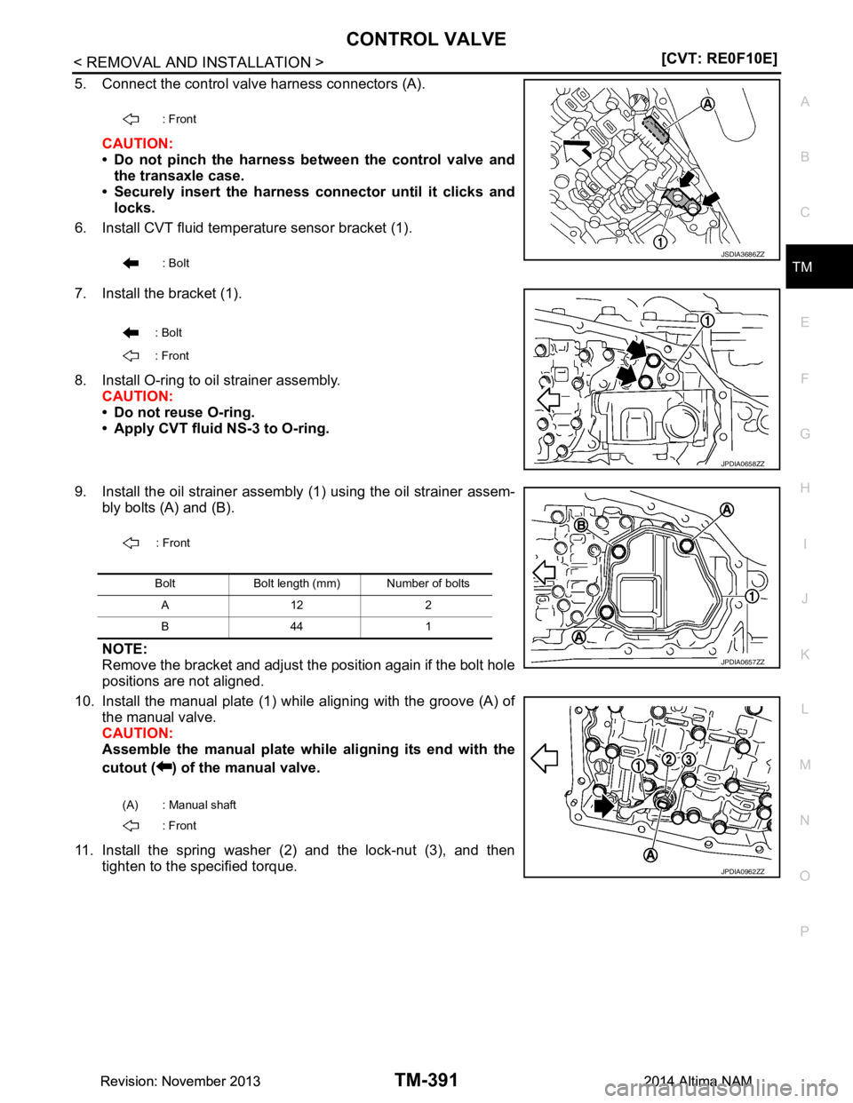
5. Connect the control valve harness connectors (A).
CAUTION:
• Do not pinch the harness be tween the control valve and
the transaxle case.
• Securely insert the harness connector until it clicks and
locks.
6. Install CVT fluid temperature sensor bracket (1).
7. Install the bracket (1).
8. Install O-ring to oil strainer assembly. CAUTION:
• Do not reuse O-ring.
• Apply CVT fluid NS-3 to O-ring.
9. Install the oil strainer assembly (1) using the oil strainer assem- bly bolts (A) and (B).
NOTE:
Remove the bracket and adjust the position again if the bolt hole
positions are not aligned.
10. Install the manual plate (1) while aligning with the groove (A) of the manual valve.
CAUTION:
Assemble the manual plate whil e aligning its end with the
cutout ( ) of the manual valve.
11. Install the spring washer (2) and the lock-nut (3), and then tighten to the specified torque.
: Front
: Bolt
JSDIA3686ZZ
: Bolt
: Front
JPDIA0658ZZ
: Front
Bolt Bolt length (mm) Number of bolts A12 2
B44 1
(A) : Manual shaft : Front
JPDIA0657ZZ
JPDIA0962ZZ
Revision: November 20132014 Altima NAMRevision: November 20132014 Altima NAM
Page 4652 of 4801
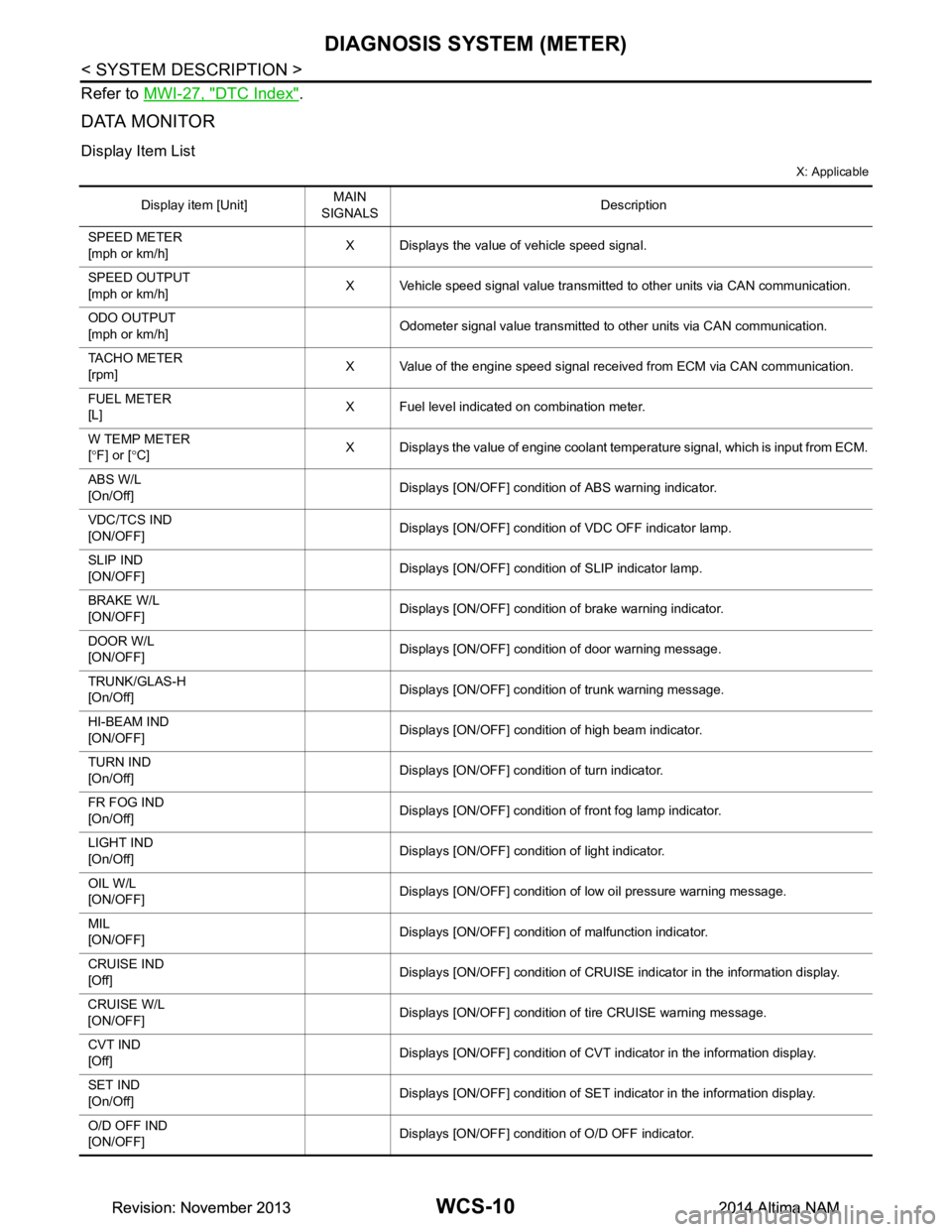
WCS-10
< SYSTEM DESCRIPTION >
DIAGNOSIS SYSTEM (METER)
Refer to MWI-27, "DTC Index".
DATA MONITOR
Display Item List
X: Applicable
Display item [Unit] MAIN
SIGNALS Description
SPEED METER
[mph or km/h] X Displays the value of vehicle speed signal.
SPEED OUTPUT
[mph or km/h] X Vehicle speed signal value transmitted to other units via CAN communication.
ODO OUTPUT
[mph or km/h] Odometer signal value transmitted to other units via CAN communication.
TACHO METER
[rpm] X Value of the engine speed signal received from ECM via CAN communication.
FUEL METER
[L] X Fuel level indicated on combination meter.
W TEMP METER
[ ° F] or [ °C] X Displays the value of engine coolant temperature signal, which is input from ECM.
ABS W/L
[On/Off] Displays [ON/OFF] condition of ABS warning indicator.
VDC/TCS IND
[ON/OFF] Displays [ON/OFF] condition of VDC OFF indicator lamp.
SLIP IND
[ON/OFF] Displays [ON/OFF] condition of SLIP indicator lamp.
BRAKE W/L
[ON/OFF] Displays [ON/OFF] condition of brake warning indicator.
DOOR W/L
[ON/OFF] Displays [ON/OFF] condition of door warning message.
TRUNK/GLAS-H
[On/Off] Displays [ON/OFF] condition of trunk warning message.
HI-BEAM IND
[ON/OFF] Displays [ON/OFF] condition of high beam indicator.
TURN IND
[On/Off] Displays [ON/OFF] condition of turn indicator.
FR FOG IND
[On/Off] Displays [ON/OFF] condition of front fog lamp indicator.
LIGHT IND
[On/Off] Displays [ON/OFF] condition of light indicator.
OIL W/L
[ON/OFF] Displays [ON/OFF] condition of low oil pressure warning message.
MIL
[ON/OFF] Displays [ON/OFF] condition of malfunction indicator.
CRUISE IND
[Off] Displays [ON/OFF]
condition of CRUISE indicator in the information display.
CRUISE W/L
[ON/OFF] Displays [ON/OFF] condition of
tire CRUISE warning message.
CVT IND
[Off] Displays [ON/OFF] condition of CVT indicator in the information display.
SET IND
[On/Off] Displays [ON/OFF] condition of SET indicator in the information display.
O/D OFF IND
[ON/OFF] Displays [ON/OFF] condition of O/D OFF indicator.
Revision: November 20132014 Altima NAMRevision: November 20132014 Altima NAM
Page 4653 of 4801
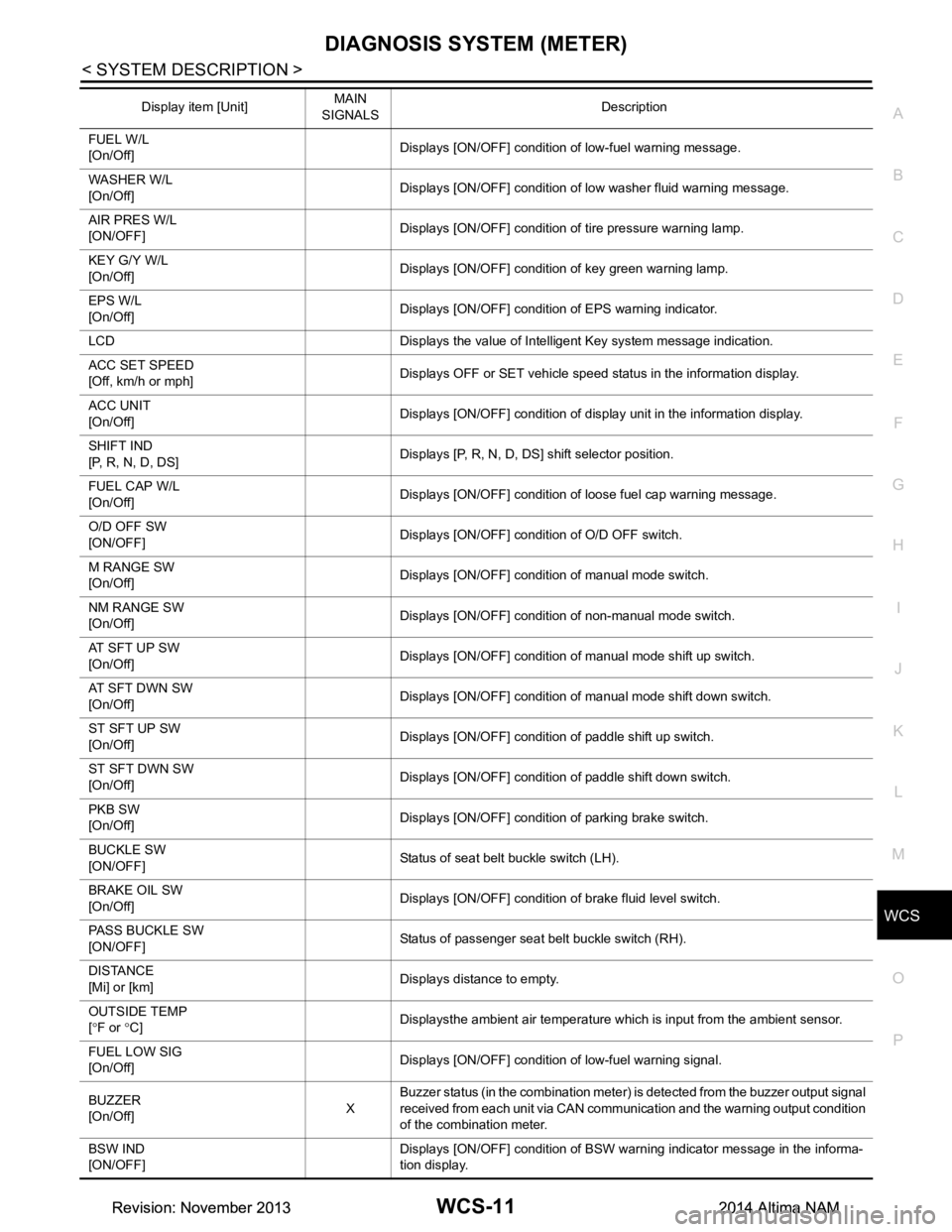
WCS
DIAGNOSIS SYSTEM (METER)WCS-11
< SYSTEM DESCRIPTION >
C
D E
F
G H
I
J
K L
M B
A
O P
FUEL W/L
[On/Off] Displays [ON/OFF] condition of low-fuel warning message.
WASHER W/L
[On/Off] Displays [ON/OFF] condition of low washer fluid warning message.
AIR PRES W/L
[ON/OFF] Displays [ON/OFF] condition of tire pressure warning lamp.
KEY G/Y W/L
[On/Off] Displays [ON/OFF] condition of key green warning lamp.
EPS W/L
[On/Off] Displays [ON/OFF] condition of EPS warning indicator.
LCD Displays the value of Intelligent Key system message indication.
ACC SET SPEED
[Off, km/h or mph] Displays OFF or SET vehicle speed status in the information display.
ACC UNIT
[On/Off] Displays [ON/OFF] condition of display unit in the information display.
SHIFT IND
[P, R, N, D, DS] Displays [P, R, N, D, DS] shift selector position.
FUEL CAP W/L
[On/Off] Displays [ON/OFF] condition of loose fuel cap warning message.
O/D OFF SW
[ON/OFF] Displays [ON/OFF] condition of O/D OFF switch.
M RANGE SW
[On/Off] Displays [ON/OFF] condition of manual mode switch.
NM RANGE SW
[On/Off] Displays [ON/OFF] condition of non-manual mode switch.
AT SFT UP SW
[On/Off] Displays [ON/OFF] condition of manual mode shift up switch.
AT SFT DWN SW
[On/Off] Displays [ON/OFF] condition of manual mode shift down switch.
ST SFT UP SW
[On/Off] Displays [ON/OFF] condition of paddle shift up switch.
ST SFT DWN SW
[On/Off] Displays [ON/OFF] condition of paddle shift down switch.
PKB SW
[On/Off] Displays [ON/OFF] condition of parking brake switch.
BUCKLE SW
[ON/OFF] Status of seat belt buckle switch (LH).
BRAKE OIL SW
[On/Off] Displays [ON/OFF] condition of brake fluid level switch.
PASS BUCKLE SW
[ON/OFF] Status of passenger seat belt buckle switch (RH).
DISTANCE
[Mi] or [km] Displays distance to empty.
OUTSIDE TEMP
[ ° F or °C] Displaysthe ambient air temperature which is input from the ambient sensor.
FUEL LOW SIG
[On/Off] Displays [ON/OFF] condition of low-fuel warning signal.
BUZZER
[On/Off] XBuzzer status (in the combination meter) is detected from the buzzer output signal
received from each unit via CAN communication and the warning output condition
of the combination meter.
BSW IND
[ON/OFF] Displays [ON/OFF] condition of BSW warning indicator message in the informa-
tion display.
Display item [Unit]
MAIN
SIGNALS Description
Revision: November 20132014 Altima NAMRevision: November 20132014 Altima NAM