brake fluid NISSAN TEANA 2014 Owner's Manual
[x] Cancel search | Manufacturer: NISSAN, Model Year: 2014, Model line: TEANA, Model: NISSAN TEANA 2014Pages: 4801, PDF Size: 51.2 MB
Page 134 of 4801

BR-38
< REMOVAL AND INSTALLATION >
REAR DISC BRAKE
REAR DISC BRAKE
BRAKE PAD
BRAKE PAD : Exploded ViewINFOID:0000000009463716
BRAKE PAD : Removal and InstallationINFOID:0000000009463717
WARNING:
Clean dust on brake calipers and brake pads with a vacuum dust collector to minimize the hazard of
airborne particles or other materials.
CAUTION:
• While removing brake caliper, do not de press brake pedal because piston will pop out.
• Do not damage piston boot.
• Keep disc brake rotors and brake pa ds free from brake fluid and grease.
• Burnish the brake pads and disc brake rotors mutually contacting surfaces after refinishing or
replacing disc brake rotors, after replacing brake pads, or if a soft pedal occurs at very low mileage.
Refer to BR-17, "Brake Burnishing"
.
REMOVAL
1. Partially drain brake fluid from the master cylinder. Refer to BR-14, "Drain and Refill".
2. Remove rear wheel and tire using power tool. Refer to WT-55, "Adjustment"
.
3. Remove the upper and lower sliding pin bolts. Refer to BR-39,
"BRAKE CALIPER ASSEMBLY : Exploded View".
NOTE:
Note the sliding pin orientation during removal. The upper sliding
pin contains a bushing.
4. Remove brake caliper from torque member. Leavi ng brake hose attached, reposition the brake caliper
aside with wire.
1. Inner cover shim 2. Inner shim 3. Inner pad
4. Outer pad 5. Outer shim 6. Outer shim cover
7. Pad retainer A. Molykote AS-880N grease B. Molykote 7439 grease
AWFIA0940ZZ
ALFIA0288ZZ
Revision: November 20132014 Altima NAM
Page 135 of 4801

REAR DISC BRAKEBR-39
< REMOVAL AND INSTALLATION >
C
D E
G H
I
J
K L
M A
B
BR
N
O P
CAUTION:
Do not twist or stretch the brake hose.
5. Remove the brake pads and shims from the torque member.
6. Remove the brake pad retainers from the torque member. CAUTION:
• When removing the brake pad retainers from the torque
member, lift in the directi on indicated by the arrow as
shown so that it does not deform.
• Replace brake pad retainers if damage exists.
INSTALLATION
Installation is in the reverse order of removal.
• Apply Molykote AS-880N grease or equivalent betw een the outer brake pad, outer shim cover and outer
shim and the inner shim and inner brake pad. Install out er shim, outer shim cover to outer brake pad, and
inner shim, inner shim cover to inner brake pad.
CAUTION:
Replace brake pad shims and covers if damage exists.
• Apply Molykote 7439 grease or equivalent between brake pad retainers and brake pad ends. Install brake pad retainers and brake pads on torque member.
CAUTION:
• Make sure the brake pad retainers are fastened properly to the torque member.
• Replace brake pad retainers if damage exists.
• Using a suitable tool, press the piston into the cylinder bore of the caliper.
• Check brake fluid level and refill as necessary. Refer to BR-8, "Inspection"
.
• Burnish contact surface between brake pads and disc brake rotors. Refer to BR-17, "Brake Burnishing"
.
BRAKE CALIPER ASSEMBLY
BRAKE CALIPER ASSEMBLY : Exploded ViewINFOID:0000000009463718
SBR556E
AWFIA0937ZZ
Revision: November 20132014 Altima NAM
Page 136 of 4801

BR-40
< REMOVAL AND INSTALLATION >
REAR DISC BRAKE
BRAKE CALIPER ASSEMBLY : Removal and Installation
INFOID:0000000009463719
WARNING:
Clean dust on brake calipers and brake pads with a vacuum dust collector to minimize the hazard of
airborne particles or other materials.
CAUTION:
• While removing brake caliper, do not depr ess brake pedal because the piston will pop out.
• Do not damage piston boot.
• Keep disc brake rotor free from brake fluid.
• Refill the brake reservoir with new brake fluid “DOT 3”.
• Do not reuse drained brake fluid.
NOTE:
When removing components such as hoses, tubes/lines, etc. , cap or plug openings to prevent fluid from spill-
ing.
REMOVAL
1. Remove rear wheel and tire using power tool. Refer to WT-55, "Adjustment".
2. Remove reservoir cap.
3. Partially drain brake fluid from the master cylinder. Refer to BR-14, "Drain and Refill"
.
4. Remove union bolt (A) and then remove brake hose from brake caliper. Discard the copper sealing wash- ers.
CAUTION:
Do not reuse copp er sealing washers.
5. Remove the upper and lower sliding pin bolts. NOTE:
Note the sliding pin orientation during removal. The upper sliding
pin contains a bushing.
6. Remove the brake caliper from the torque member.
7. Remove the brake pads and shims from the torque member.
8. Remove the torque member bolts and the torque member.
1. Union bolt 2. Brake hose 3. Copper sealing washers
4. Cap 5. Bleeder valve 6. Lower sliding pin bolt
7. Upper sliding pin bolt 8. Upper sliding pin bushing 9. Brake caliper
10. Piston seal 11. Piston 12. Piston boot
13. Retaining ring 14. Sliding pin boot 15. Torque member bolt
16. Washers 17 Torque member A. Molykote AS-880N grease
B. Rubber grease
NOTE:
RH side caliper shown, LH side caliper similar.
ALFIA0288ZZ
Revision: November 20132014 Altima NAM
Page 137 of 4801

REAR DISC BRAKEBR-41
< REMOVAL AND INSTALLATION >
C
D E
G H
I
J
K L
M A
B
BR
N
O P
9. Remove the disc brake rotor. If reusing the disc brake rotor apply matching marks as shown.
INSTALLATION
Installation is in the reverse order of removal.
• Tighten components to specification. Refer to BR-39, "BRAKE CALIPER ASSEMBLY : Exploded View"
.
• Align the L-shaped pin on the brake hose in the hole in the brake
caliper, then install the brake hose with new copper sealing wash-
ers (1) and tighten the union bolt (A) to the specified torque. Refer
to BR-23, "REAR : Exploded View"
.
CAUTION:
Do not reuse copper sealing washers.
• Refill with new brake fluid and bleed air fr om the brake hydraulic system. Refer to BR-14, "Bleeding Brake
System".
SDIA2638E
AWFIA0795ZZ
Revision: November 20132014 Altima NAM
Page 139 of 4801
FRONT DISC BRAKEBR-43
< UNIT DISASSEMBLY AND ASSEMBLY >
C
D E
G H
I
J
K L
M A
B
BR
N
O P
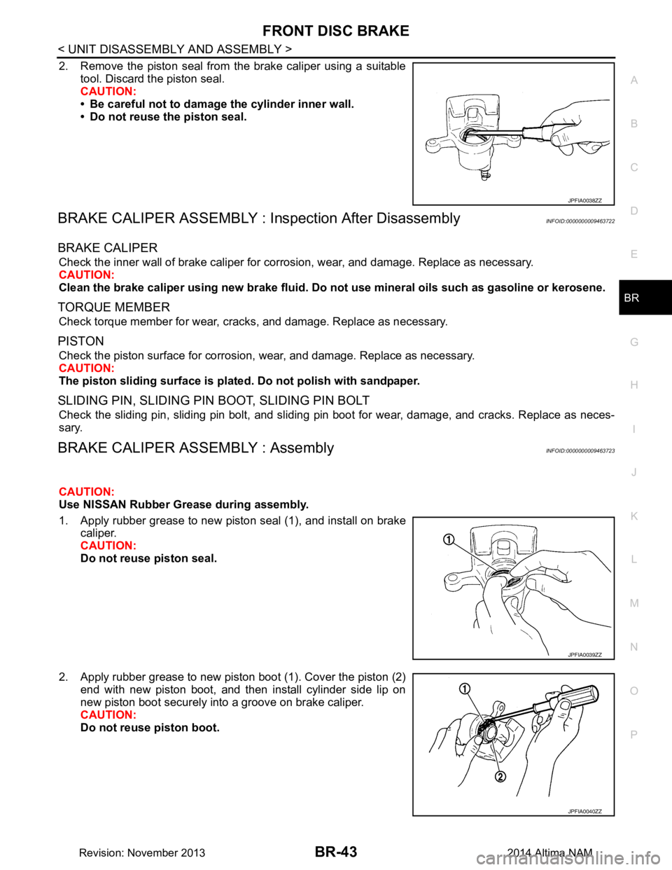
2. Remove the piston seal from the brake caliper using a suitable tool. Discard the piston seal.
CAUTION:
• Be careful not to damage the cylinder inner wall.
• Do not reuse the piston seal.
BRAKE CALIPER ASSEMBLY : In spection After DisassemblyINFOID:0000000009463722
BRAKE CALIPER
Check the inner wall of brake caliper for co rrosion, wear, and damage. Replace as necessary.
CAUTION:
Clean the brake caliper using new br ake fluid. Do not use mineral oils such as gasoline or kerosene.
TORQUE MEMBER
Check torque member for wear, cracks, and damage. Replace as necessary.
PISTON
Check the piston surface for corrosion, wear, and damage. Replace as necessary.
CAUTION:
The piston sliding surface is plated . Do not polish with sandpaper.
SLIDING PIN, SLIDING PIN BOOT, SLIDING PIN BOLT
Check the sliding pin, sliding pin bolt, and sliding pin boot for wear, damage, and cracks. Replace as neces-
sary.
BRAKE CALIPER ASSEMBLY : AssemblyINFOID:0000000009463723
CAUTION:
Use NISSAN Rubber Grease during assembly.
1. Apply rubber grease to new piston seal (1), and install on brake caliper.
CAUTION:
Do not reuse piston seal.
2. Apply rubber grease to new piston boot (1). Cover the piston (2) end with new piston boot, and then install cylinder side lip on
new piston boot securely into a groove on brake caliper.
CAUTION:
Do not reuse piston boot.
JPFIA0038ZZ
JPFIA0039ZZ
JPFIA0040ZZ
Revision: November 20132014 Altima NAM
Page 142 of 4801

BR-46
< UNIT DISASSEMBLY AND ASSEMBLY >
REAR DISC BRAKE
2. Place a wooden block in the brake caliper as shown, and blowair into the union bolt hole to the remove piston and piston boot.
WARNING:
Do not get fingers caught be tween the piston and wooden
block.
3. Remove the piston seal from the brake caliper using a suitable tool. Discard the piston seal.
CAUTION:
• Be careful not to damage the cylinder inner wall.
• Do not reuse the piston seal.
BRAKE CALIPER ASSEMBLY : In spection After DisassemblyINFOID:0000000009463726
BRAKE CALIPER
Check the inner wall of the cylinder for corrosion, wear, and damage. Replace as necessary.
CAUTION:
Clean the brake caliper using new br ake fluid. Do not use mineral oils such as gasoline or kerosene.
TORQUE MEMBER
Check the torque member for wear, cr acks, and damage. Replace as necessary.
PISTON
Check the piston surface for corrosion, wear, and damage. Replace as necessary.
CAUTION:
The piston sliding surface is plated . Do not polish with sandpaper.
SLIDING PIN BOLT, SLIDING PIN BOOT
Check the sliding pin bolt and sliding pin boot fo r wear, damage, and cracks. Replace as necessary.
BRAKE CALIPER ASSEMBLY : AssemblyINFOID:0000000009463727
CAUTION:
Use NISSAN Rubber Grease during assembly.
1. Apply rubber grease to new piston seal (1), and install on brake caliper.
CAUTION:
Do not reuse piston seal.
BRD0041D
JPFIA0038ZZ
JPFIA0039ZZ
Revision: November 20132014 Altima NAM
Page 144 of 4801
BR-48
< SERVICE DATA AND SPECIFICATIONS (SDS)
SERVICE DATA AND SPECIFICATIONS (SDS)
SERVICE DATA AND SPECIFICATIONS (SDS)
SERVICE DATA AND SPECIFICATIONS (SDS)
General SpecificationsINFOID:0000000009463728
Unit: mm (in)
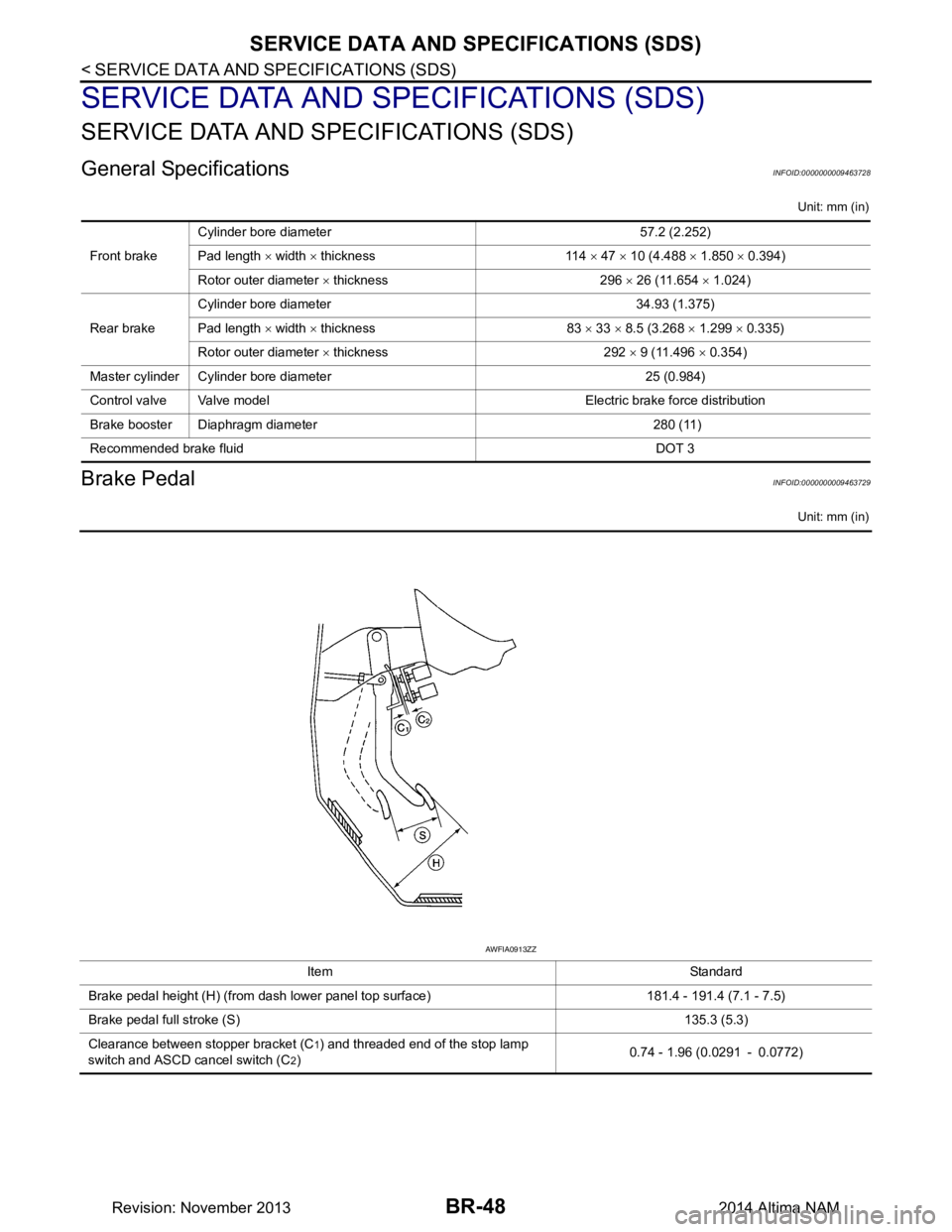
Brake PedalINFOID:0000000009463729
Unit: mm (in)
Front brakeCylinder bore diameter 57.2 (2.252)
Pad length × width × thickness 114 × 47 × 10 (4.488 × 1.850 × 0.394)
Rotor outer diameter × thickness 296 × 26 (11.654 × 1.024)
Rear brake Cylinder bore diameter 34.93 (1.375)
Pad length × width × thickness 83 × 33 × 8.5 (3.268 × 1.299 × 0.335)
Rotor outer diameter × thickness 292 × 9 (11.496 × 0.354)
Master cylinder Cylinder bore diameter 25 (0.984)
Control valve Valve model Electric brake force distribution
Brake booster Diaphragm diameter 280 (11)
Recommended brake fluid DOT 3
Item Standard
Brake pedal height (H) (from dash lower panel top surface) 181.4 - 191.4 (7.1 - 7.5)
Brake pedal full stroke (S) 135.3 (5.3)
Clearance between stopper bracket (C
1) and threaded end of the stop lamp
switch and ASCD cancel switch (C
2) 0.74 - 1.96 (0.0291 - 0.0772)
AWFIA0913ZZ
Revision: November 20132014 Altima NAM
Page 147 of 4801

BRC-1
BRAKES
C
D E
G H
I
J
K L
M
SECTION BRC
A
B
BRC
N
O P
CONTENTS
BRAKE CONTROL SYSTEM
VDC/TCS/ABS
PRECAUTION ................ ...............................
4
PRECAUTIONS .............................................. .....4
Precaution for Supplemental Restraint System
(SRS) "AIR BAG" and "SEAT BELT PRE-TEN-
SIONER" ............................................................. ......
4
Precaution for Brake System ....................................4
Precaution for Brake Control .....................................5
Precaution for CAN System ................................ ......5
Precaution for Work ..................................................6
PREPARATION ............................................7
PREPARATION .............................................. .....7
Special Service Tool ........................................... ......7
Commercial Service Tool ..........................................7
SYSTEM DESCRIPTION ..............................8
COMPONENT PARTS ................................... .....8
Component Parts Location .................................. ......8
Component Description .............................................9
ABS Actuator and Electric Unit (Control Unit) ...........9
Wheel Sensor and Sensor Rotor ............................10
Stop Lamp Switch ...................................................10
Steering Angle Sensor ............................................10
Brake Fluid Level Switch .........................................10
Vacuum Sensor .......................................................10
Parking Brake Switch ..............................................11
VDC OFF Switch .....................................................11
SYSTEM .............................................................12
VDC/TCS/ABS ....................................................... ....12
VDC/TCS/ABS : System Diagram ...........................12
VDC/TCS/ABS : System De scription ......................12
VDC/TCS/ABS : VDC Functi on ...............................23
VDC/TCS/ABS : TCS Functi on ...............................25
VDC/TCS/ABS : ABS Function ........................... ....27
VDC/TCS/ABS : EBD Functi on ...............................28
VDC/TCS/ABS : Fail-safe ... .....................................29
DIAGNOSIS SYSTEM [ABS ACTUATOR
AND ELECTRIC UNIT (CONTROL UNIT)] .......
33
CONSULT Function (ABS) .................................. ....33
ECU DIAGNOSIS INFORMATION ..............38
ABS ACTUATOR AND ELECTRIC UNIT
(CONTROL UNIT) .............................................
38
Reference Value .................................................. ....38
Fail-safe ...................................................................41
DTC Inspection Priority Chart ..................................44
DTC Index ...............................................................45
WIRING DIAGRAM ......................................47
BRAKE CONTROL SYSTEM ...........................47
Wiring Diagram .................................................... ....47
BASIC INSPECTION ...................................55
DIAGNOSIS AND REPAIR WORK FLOW .......55
Work Flow ............................................................ ....55
Diagnostic Work Sheet ............................................56
ADDITIONAL SERVICE WHEN REPLACING
ABS ACTUATOR AND ELECTRIC UNIT
(CONTROL UNIT) .............................................
57
Description ........................................................... ....57
ADJUSTMENT OF STEERING ANGLE SEN-
SOR NEUTRAL POSITION ...............................
58
Description ........................................................... ....58
Work Procedure .......................................................58
CONFIGURATION [ABS ACTUATOR AND
ELECTRIC UNIT (CONTROL UNIT)] ................
60
Work Procedure ................................................... ....60
CALIBRATION OF DECEL G SENSOR ...........62
Description ...............................................................62
Revision: November 20132014 Altima NAMRevision: November 20132014 Altima NAM
Page 148 of 4801

BRC-2
Work Procedure ......................................................62
DTC/CIRCUIT DIAGNOSIS ...................... ...64
C1101, C1102, C1103, C1104 WHEEL SEN-
SOR ................................................................. ...
64
DTC Logic ............................................................ ...64
Diagnosis Procedure ..............................................64
C1105, C1106, C1107, C1108 WHEEL SEN-
SOR ................................................................. ...
68
DTC Logic ............................................................ ...68
Diagnosis Procedure ..............................................68
C1109 POWER AND GROUND SYSTEM .........70
DTC Logic ............................................................ ...70
Diagnosis Procedure ..............................................70
C1110, C1153, C1170 ABS ACTUATOR AND
ELECTRIC UNIT (CONTROL UNIT) .............. ...
72
DTC Logic ............................................................ ...72
Diagnosis Procedure ..............................................72
C1111 PUMP MOTOR .......................................73
DTC Logic ............................................................ ...73
Diagnosis Procedure ..............................................73
C1113, C1145, C1146 YAW RATE/SIDE/DE-
CEL G SENSOR ............................................. ...
75
DTC Logic ............................................................ ...75
Diagnosis Procedure ..............................................75
C1115 ABS SENSOR [ABNORMAL SIGNAL] ...76
DTC Logic ............................................................ ...76
Diagnosis Procedure ..............................................76
C1116 STOP LAMP SWITCH ............................78
DTC Logic ............................................................ ...78
Diagnosis Procedure ..............................................78
C1120, C1122, C1124, C1126 ABS IN VALVE
SYSTEM ............ .............................................. ...
80
DTC Logic ............................................................ ...80
Diagnosis Procedure ..............................................80
C1121, C1123, C1125, C1127 ABS OUT
VALVE SYSTEM ............................................. ...
82
DTC Logic ............................................................ ...82
Diagnosis Procedure ..............................................82
C1130 ENGINE SIGNAL ...................................84
DTC Logic ............................................................ ...84
Diagnosis Procedure ..............................................84
C1140 ACTUATOR RELAY SYSTEM ...............85
DTC Logic ............................................................ ...85
Diagnosis Procedure ..............................................85
C1142 PRESS SENSOR ...................................87
DTC Logic ............................................................ ...87
Diagnosis Procedure ..............................................87
C1143 STEERING ANGLE SENSOR ...............88
DTC Logic ............................................................ ...88
Diagnosis Procedure ...............................................88
C1144 INCOMPLETE STEERING ANGLE
SENSOR ADJUSTMENT ............................... ...
90
DTC Logic ............................................................ ...90
Diagnosis Procedure ...............................................90
C1154 PNP SWITCH .........................................91
Description ........................................................... ...91
DTC Logic ...............................................................91
Diagnosis Procedure ...............................................91
Special Repair Requirement ...................................91
C1155 BR FLUID LEVEL LOW .........................93
DTC Logic ............................................................ ...93
Diagnosis Procedure ...............................................93
Component Inspection ............................................94
C1160 DECEL G SEN SET ...............................95
DTC Logic ............................................................ ...95
Diagnosis Procedure ...............................................95
C1164, C1165, C1166, C1167 CV/SV SYS-
TEM ................................................................. ...
96
DTC Logic ............................................................ ...96
Diagnosis Procedure ...............................................96
C1197 VACUUM SENSOR ............................. ...98
DTC Logic ............................................................ ...98
Diagnosis Procedure ...............................................98
C1198 VACUUM SENSOR ............................. ..100
DTC Logic ............................................................ .100
Diagnosis Procedure .............................................100
C1199 BRAKE BOOSTER ............................. ..102
DTC Logic ............................................................ .102
Diagnosis Procedure .............................................102
C119A VACUUM SENSOR ..............................104
DTC Logic ............................................................ .104
Diagnosis Procedure .............................................104
U1000 CAN COMM CIRCUIT ...........................106
DTC Logic ............................................................ .106
Diagnosis Procedure .............................................106
U1002 SYSTEM COMM (CAN) ........................107
DTC Logic ............................................................ .107
Diagnosis Procedure .............................................107
PARKING BRAKE SWITCH .............................108
Component Function Check ................................ .108
Diagnosis Procedure .............................................108
Component Inspection ..........................................109
VDC OFF SWITCH ...........................................110
Component Function Check ................................ .110
Diagnosis Procedure .............................................110
Component Inspection ..........................................111
Revision: November 20132014 Altima NAMRevision: November 20132014 Altima NAM
Page 150 of 4801

BRC-4
< PRECAUTION >[VDC/TCS/ABS]
PRECAUTIONS
PRECAUTION
PRECAUTIONS
Precaution for Supplemental Restraint Syst
em (SRS) "AIR BAG" and "SEAT BELT
PRE-TENSIONER"
INFOID:0000000009951721
The Supplemental Restraint System such as “A IR BAG” and “SEAT BELT PRE-TENSIONER”, used along
with a front seat belt, helps to reduce the risk or severi ty of injury to the driver and front passenger for certain
types of collision. Information necessary to service the system safely is included in the SR and SB section of
this Service Manual.
WARNING:
• To avoid rendering the SRS inopera tive, which could increase the risk of personal injury or death in
the event of a collision which would result in air bag inflation, all maintenance must be performed by
an authorized NISS AN/INFINITI dealer.
• Improper maintenance, including in correct removal and installation of the SRS, can lead to personal
injury caused by unintent ional activation of the system. For re moval of Spiral Cable and Air Bag
Module, see the SR section.
• Do not use electrical test equipmen t on any circuit related to the SRS unless instructed to in this
Service Manual. SRS wiring harn esses can be identified by yellow and/or orange harnesses or har-
ness connectors.
PRECAUTIONS WHEN USING POWER TOOLS (AIR OR ELECTRIC) AND HAMMERS
WARNING:
• When working near the Airbag Diagnosis Sensor Unit or other Airbag System sensors with the Igni-
tion ON or engine running, DO NOT use air or electri c power tools or strike near the sensor(s) with a
hammer. Heavy vibration could activate the sensor( s) and deploy the air bag(s), possibly causing
serious injury.
• When using air or electric power tools or hammers , always switch the Ignition OFF, disconnect the
battery and wait at least three minutes before performing any service.
Precaution for Brake SystemINFOID:0000000009463735
WARNING:
Clean any dust from the front brake and rear br ake using a vacuum dust collector. Do not blow by
compressed air.
• Brake fluid use refer to BR-8, "Inspection"
.
• Do not reuse drained brake fluid.
• Do not spill or splash brake fluid on painted surfaces. Brake fluid may seriously damage paint. Wipe it off immediately and wash with water if it gets on a painted surface.
• Always confirm the specified tightening torque when installing the brake pipes.
• After pressing the brake pedal more deeply or harder t han normal driving, such as air bleeding, check each
item of brake pedal. Adjust brake pedal if it is outside the standard value.
• Do not use mineral oils such as gasoline or light oil to clean. They may damage rubber parts and cause
improper operation.
• Always loosen the brake tube flar e nut with a flare nut wrench.
• Tighten the brake tube flare nut to the specified torque with a crow-
foot (A) and torque wrench (B).
• Always connect the battery terminal when moving the vehicle.
• Turn the ignition switch OFF and disconnect the ABS actuator and
electric unit (control unit) harness connector or the battery negative
terminal before performing the work.
• Check that no brake fluid leakage is present after replacing the parts.
JPFIA0001ZZ
Revision: November 20132014 Altima NAMRevision: November 20132014 Altima NAM