open hood NISSAN TEANA 2014 Service Manual
[x] Cancel search | Manufacturer: NISSAN, Model Year: 2014, Model line: TEANA, Model: NISSAN TEANA 2014Pages: 4801, PDF Size: 51.2 MB
Page 770 of 4801

DLK-2
TRUNK LID OPENER SYSTEM ............................ ...36
TRUNK LID OPENER SYSTEM : System Dia-
gram .................................................................... ...
37
TRUNK LID OPENER SYSTEM : System De-
scription ............................................................... ...
37
SYSTEM (INTEGRATED HOMELINK
TRANSMITTER) ............................................. ...
40
System Description .............................................. ...40
SYSTEM (TRUNK LID OPENER SYSTEM) ......41
System Diagram .................................................. ...41
System Description .................................................41
DIAGNOSIS SYSTEM (BCM) ............................42
COMMON ITEM ..................................................... ...42
COMMON ITEM : CONSULT Function (BCM -
COMMON ITEM) ................................................. ...
42
DOOR LOCK .......................................................... ...43
DOOR LOCK : CONSULT Function (BCM -
DOOR LOCK) ...................................................... ...
43
INTELLIGENT KEY ................................................ ...44
INTELLIGENT KEY : CONSULT Function (BCM -
INTELLIGENT KEY) ........ .......................................
44
TRUNK ................................................................... ...47
TRUNK : CONSULT Function (BCM - TRUNK) .....47
ECU DIAGNOSIS INFORMATION ..............48
ECM, IPDM E/R, BCM .................................... ...48
List of ECU Reference ......................................... ...48
WIRING DIAGRAM .....................................49
HOMELINK UNIVERSAL TRANSCEIVER ..... ...49
Wiring Diagram .................................................... ...49
POWER DOOR LOCK SYSTEM .......................51
Wiring Diagram .................................................... ...51
INTELLIGENT KEY SYSTEM ............................61
Wiring Diagram .................................................... ...61
TRUNK LID OPENER ........................................77
Wiring Diagram .................................................... ...77
BASIC INSPECTION ...................................81
DIAGNOSIS AND REPAIR WORKFLOW ...... ...81
Work Flow ............................................................ ...81
INSPECTION AND ADJUSTMENT ...................84
ADDITIONAL SERVICE WHEN REPLACING
CONTROL UNIT ..................................................... ...
84
ADDITIONAL SERVICE WHEN REPLACING
CONTROL UNIT : Description ............................. ...
84
ADDITIONAL SERVICE WHEN REPLACING
CONTROL UNIT : Special Repair Requirement .....
84
DTC/CIRCUIT DIAGNOSIS ........................85
U1000 CAN COMM CIRCUIT ......................... ...85
Description ........................................................... ...85
DTC Logic ...............................................................85
Diagnosis Procedure ...............................................85
U1010 CONTROL UNIT (CAN) .........................86
DTC Logic ............................................................ ...86
Diagnosis Procedure ...............................................86
Special Repair Requirement ...................................86
B261B REMOTE ENGINE START ....................87
DTC Logic ............................................................ ...87
Diagnosis Procedure ...............................................87
B2621 INSIDE ANTENNA .............................. ...88
DTC Logic ............................................................ ...88
Diagnosis Procedure ...............................................88
B2622 INSIDE ANTENNA .............................. ...90
DTC Logic ............................................................ ...90
Diagnosis Procedure ...............................................90
B26FD SHIFT LOCK SOLENOID .....................92
DTC Logic ............................................................ ...92
Diagnosis Procedure ...............................................92
B26FE HOOD SWITCH .....................................95
DTC Logic ............................................................ ...95
Diagnosis Procedure ..............................................95
Component Inspection ............................................96
B26FF REMOTE KEYLESS ENTRY RECEIV-
ER ................................................................... ...
97
DTC Logic ............................................................ ...97
Diagnosis Procedure ...............................................97
POWER SUPPLY AND GROUND CIRCUIT .....99
Diagnosis Procedure ............................................ ...99
DOOR SWITCH ................................................100
Description ........................................................... .100
Component Function Check ................................100
Diagnosis Procedure .............................................100
Component Inspection ..........................................102
DOOR LOCK AND UNLOCK SWITCH ............103
DRIVER SIDE ......................................................... .103
DRIVER SIDE : Description ..................................103
DRIVER SIDE : Component Function Check ......103
DRIVER SIDE : Diagnosis Procedure (With LH
and RH Anti-Pinch) .............................................. .
103
DRIVER SIDE : Diagnosis Procedure (With LH
Anti-Pinch Only) ................................................... .
104
PASSENGER SIDE .................................................105
PASSENGER SIDE : Descripti on .........................105
PASSENGER SIDE :
Component Function Check ............................... .
106
Revision: November 20132014 Altima NAMRevision: November 20132014 Altima NAM
Page 772 of 4801

DLK-4
INTELLIGENT KEY SYSTEM SYMPTOMS ....152
Symptom Table ................................................... ..152
DOOR LOCK FUNCTION SYMPTOMS ..........153
DOOR LOCK AND UNLOCK SWITCH ................. ..153
DOOR LOCK AND UNLOCK SWITCH : Symptom
Table .................................................................... ..
153
DOOR REQUEST SWITCH ................................... ..153
DOOR REQUEST SWITCH : Symptom Table ......153
INTELLIGENT KEY ................................................ ..154
INTELLIGENT KEY : Symptom Table ...................154
TRUNK OPEN FUNCTION SYMPTOMS ....... .156
TRUNK LID OPENER SWITCH ............................. ..156
TRUNK LID OPENER SWITCH : Symptom Table ..156
TRUNK REQUEST SWITCH .................................. ..156
TRUNK REQUEST SWITCH : Symptom Table .....156
INTELLIGENT KEY ................................................ ..156
INTELLIGENT KEY : Symptom Table ...................156
WARNING FUNCTION SYMPTOMS .............. .158
Symptom Table ................................................... ..158
KEY REMINDER FUNCTION SYMPTOMS .....160
Symptom Table ................................................... ..160
HAZARD FUNCTION .......................................161
Symptom Table ................................................... ..161
HORN FUNCTION ...........................................162
Symptom Table ................................................... ..162
INTEGRATED HOMELINK TRANSMITTER ...163
Symptom Table ................................................... ..163
SQUEAK AND RATTLE TROUBLE DIAG-
NOSES ......................... ....................................
164
Work Flow ............................................................ ..164
Generic Squeak and Rattle Troubleshooting .........165
Diagnostic Worksheet ............................................168
REMOVAL AND INSTALLATION ..............170
HOOD .............................................................. .170
HOOD ASSEMBLY ................................................ ..170
HOOD ASSEMBLY : Exploded View ................... ..170
HOOD ASSEMBLY : Removal and Installation .....170
HOOD ASSEMBLY : Adjustme nt ........................ ..172
HOOD HINGE ......................................................... ..174
HOOD HINGE : Removal and Installation .............174
HOOD SUPPORT ROD .......................................... ..175
HOOD SUPPORT ROD : Removal and Installa-
tion ....................................................................... ..
175
HOOD LOCK CONTROL ....................................... ..175
HOOD LOCK CONTROL : Component Parts Lo-
cation ................................................................... .
175
HOOD LOCK CONTROL : Removal and Installa-
tion ....................................................................... .
176
RADIATOR CORE SUPPORT .........................179
Removal and Installation .......................................179
FRONT FENDER ............................................ ..181
Exploded View ..................................................... .181
Removal and Installation .......................................181
Adjustment ........................................................... .182
FRONT DOOR ..................................................184
DOOR ASSEMBLY .................................................184
DOOR ASSEMBLY : Removal and Installation ....184
DOOR ASSEMBLY : Adjustme nt ..........................186
DOOR STRIKER .................................................... .188
DOOR STRIKER : Removal and Installation ........188
DOOR HINGE ......................................................... .188
DOOR HINGE : Removal and Installation ............188
DOOR CHECK LINK .............................................. .189
DOOR CHECK LINK : Removal and Installation ..189
REAR DOOR ....................................................190
DOOR ASSEMBLY .................................................190
DOOR ASSEMBLY : Removal and Installation ....190
DOOR ASSEMBLY : Adjustme nt ..........................191
DOOR STRIKER .................................................... .194
DOOR STRIKER : Removal and Installation ........194
DOOR HINGE ......................................................... .194
DOOR HINGE : Removal and Installation ............194
DOOR CHECK LINK .............................................. .195
DOOR CHECK LINK : Removal and Installation ..195
DOOR HANDLE ...............................................197
FRONT DOOR HANDLE ........................................ .197
FRONT DOOR HANDLE : Exploded View ...........197
FRONT DOOR HANDLE : Removal and Installa-
tion - Inside Handle .............................................. .
197
FRONT DOOR HANDLE : Removal and Installa-
tion - Outside Handle ........................................... .
198
REAR DOOR HANDLE .......................................... .200
REAR DOOR HANDLE : Exploded View ..............200
REAR DOOR HANDLE : Removal and Installation
- Inside Handle ..................................................... .
200
REAR DOOR HANDLE : Removal and Installation
- Outside Handle .................................................. .
201
DOOR LOCK ....................................................203
FRONT DOOR LOCK ............................................. .203
FRONT DOOR LOCK : Exploded View ................203
FRONT DOOR LOCK : Removal and Installation .203
Revision: November 20132014 Altima NAMRevision: November 20132014 Altima NAM
Page 786 of 4801
DLK-18
< SYSTEM DESCRIPTION >
COMPONENT PARTS
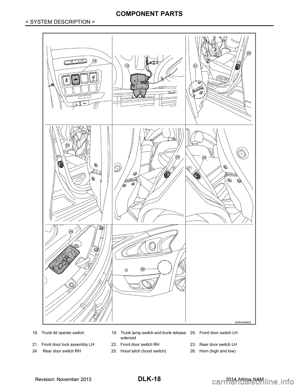
18. Trunk lid opener switch 19. Trunk lamp switch and trunk release solenoid 20. Front door switch LH
21. Front door lock assembly LH 22. Front door switch RH 23. Rear door switch LH
24. Rear door switch RH 25. Hood latch (hood switch) 26. Horn (high and low)
AWKIA2688ZZ
Revision: November 20132014 Altima NAMRevision: November 20132014 Altima NAM
Page 787 of 4801
COMPONENT PARTSDLK-19
< SYSTEM DESCRIPTION >
C
D E
F
G H
I
J
L
M A
B
DLK
N
O P
INTELLIGENT KEY SYSTEM : Component DescriptionINFOID:0000000009461769
INTEGRATED HOMELINK TRANSMITTER
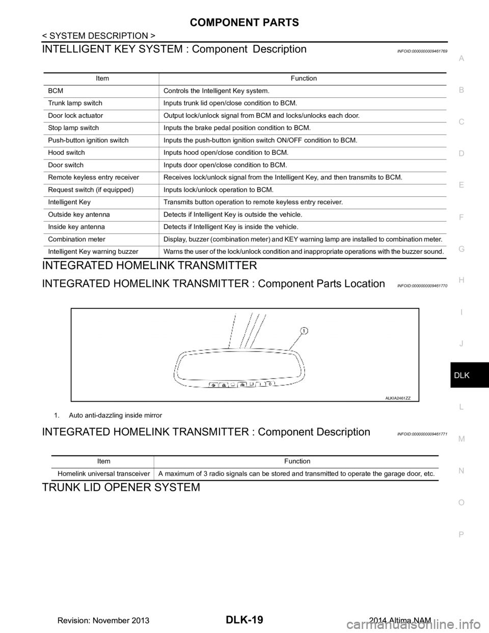
INTEGRATED HOMELINK TRANSMI TTER : Component Parts LocationINFOID:0000000009461770
INTEGRATED HOMELINK TRANSM ITTER : Component DescriptionINFOID:0000000009461771
TRUNK LID OPENER SYSTEM
Item Function
BCM Controls the Intelligent Key system.
Trunk lamp switch Inputs trunk lid open/close condition to BCM.
Door lock actuator Output lock/unlock signal from BCM and locks/unlocks each door.
Stop lamp switch Inputs the brake pedal position condition to BCM.
Push-button ignition switch Inputs the push-button ignition switch ON/OFF condition to BCM.
Hood switch Inputs hood open/close condition to BCM.
Door switch Inputs door open/close condition to BCM.
Remote keyless entry receiver Receives lock/unlock signal from the Intelligent Key, and then transmits to BCM.
Request switch (if equipped) Inputs lock/unlock operation to BCM.
Intelligent Key Transmits button operation to remote keyless entry receiver.
Outside key antenna Detects if Intelligent Key is outside the vehicle.
Inside key antenna Detects if Intelligent Key is inside the vehicle.
Combination meter Display, buzzer (combination meter) and KEY warning lamp are installed to combination meter.
Intelligent Key warning buzzer Warns the user of the lock/unlock condition and inappropriate operations with the buzzer sound.
1. Auto anti-dazzling inside mirror
ALKIA2461ZZ
Item Function
Homelink universal transceiver A maximum of 3 radio signals can be stored and transmitted to operate the garage door, etc.
Revision: November 20132014 Altima NAMRevision: November 20132014 Altima NAM
Page 795 of 4801
SYSTEM (INTELLIGENT KEY SYSTEM)DLK-27
< SYSTEM DESCRIPTION >
C
D E
F
G H
I
J
L
M A
B
DLK
N
O P
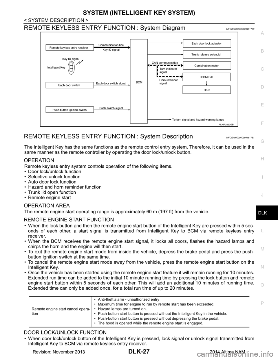
REMOTE KEYLESS ENTRY F UNCTION : System DiagramINFOID:0000000009461780
REMOTE KEYLESS ENTRY FUNCT ION : System DescriptionINFOID:0000000009461781
The Intelligent Key has the same functions as the remote control entry system. Therefore, it can be used in the
same manner as the remote controller by operating the door lock/unlock button.
OPERATION
Remote keyless entry system controls operation of the following items.
• Door lock/unlock function
• Selective unlock function
• Auto door lock function
• Hazard and horn reminder function
• Trunk lid open function
• Remote engine start
OPERATION AREA
The remote engine start operating range is appr oximately 60 m (197 ft) from the vehicle.
REMOTE ENGINE START FUNCTION
• When the lock button and then the remote engine start butt on of the Intelligent Key are pressed within 5 sec-
onds of each other, a start signal is transmitted from Intelligent Key to BCM via remote keyless entry
receiver.
• When the BCM receives the remote engine start signal , it locks all doors, flashes the hazard lamps and
chirps the horn and the engine will then start.
• To exit the remote engine start mode from inside t he vehicle, depress the brake pedal and press the push-
button ignition switch at the same time.
• To cancel the remote engine start mode away from t he vehicle, press the remote engine start button on the
Intelligent Key.
• Once the vehicle has been started using the remote engi ne start feature it will remain running for 10 minutes.
Extended run time can be added to the initial 10 minute running time by pressing the lock button and remote
engine start button within 5 seconds of each other. Th is will add an additional 10 minutes of running time.
Extended time can only be added once, for a total run time of up to 20 minutes.
DOOR LOCK/UNLOCK FUNCTION
• When door lock/unlock button of the Intelligent Key is pr essed, lock signal or unlock signal transmitted from
Intelligent Key to BCM via remote keyless entry receiver.
ALKIA2592GB
Remote engine start cancel opera-
tion • Anti-theft alarm - unauthorized entry
• Maximum time for engine to run by remote start has been exceeded.
• Hazard lamps are turned on.
• Push-button start button is pressed without the Intelligent Key in the vehicle.
• Push-button start button is pressed without depressing the brake pedal.
• The hood is opened while the remote engine start is engaged.
Revision: November 20132014 Altima NAMRevision: November 20132014 Altima NAM
Page 799 of 4801
SYSTEM (INTELLIGENT KEY SYSTEM)DLK-31
< SYSTEM DESCRIPTION >
C
D E
F
G H
I
J
L
M A
B
DLK
N
O P
• To exit the remote engine start mode from inside t he vehicle, depress the brake pedal and press the push-
button ignition switch at the same time.
• To cancel the remote engine start mode away from t he vehicle, press the remote engine start button on the
Intelligent Key.
• Once the vehicle has been started using the remote engi ne start feature it will remain running for 10 minutes.
Extended run time can be added to the initial 10 minute running time by pressing the lock button and remote
engine start button within 5 seconds of each other. Th is will add an additional 10 minutes of running time.
Extended time can only be added once, for a total run time of up to 20 minutes.
HAZARD AND HORN REMINDER FUNCTION
When remote engine start is initiated by Intelligent Key, BCM blinks hazard warning lamps as a reminder.
The hazard and horn reminder has a horn chirp m ode (C mode) and a non-horn chirp mode (S mode).
Operating Function of Hazard and Horn Reminder
Hazard and horn reminder does not operate in the following conditions.
• Ignition switch position is ON.
• Door is open (only lock operation)
How to Change Hazard and Horn Reminder Mode
With CONSULT
Hazard and horn reminder operation mode can be changed using CONSULT.
Refer to BCS-22, "INTELLIGENT KEY : CONSUL T Function (BCM - INTELLIGENT KEY)"
.
Without CONSULT
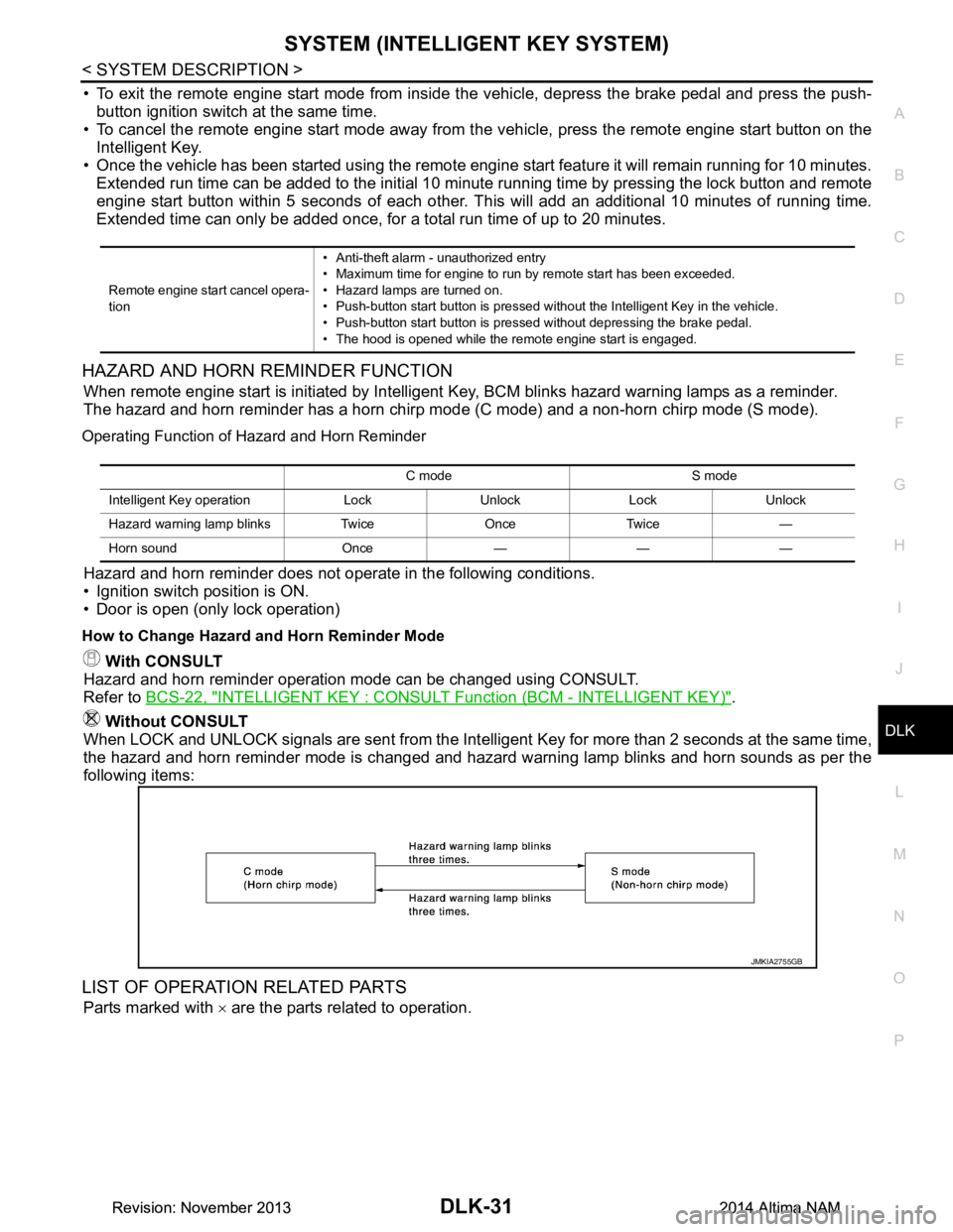
When LOCK and UNLOCK signals are sent from the Intelligent Key for more than 2 seconds at the same time,
the hazard and horn reminder mode is changed and hazard warning lamp blinks and horn sounds as per the
following items:
LIST OF OPERATION RELATED PARTS
Parts marked with × are the parts related to operation.
Remote engine start cancel opera-
tion • Anti-theft alarm - unauthorized entry
• Maximum time for engine to run by remote start has been exceeded.
• Hazard lamps are turned on.
• Push-button start button is pressed without the Intelligent Key in the vehicle.
• Push-button start button is pressed without depressing the brake pedal.
• The hood is opened while the remote engine start is engaged.
C mode S mode
Intelligent Key operation Lock Unlock Lock Unlock
Hazard warning lamp blinks Twice Once Twice —
Horn sound Once — — —
JMKIA2755GB
Revision: November 20132014 Altima NAMRevision: November 20132014 Altima NAM
Page 863 of 4801
B26FE HOOD SWITCHDLK-95
< DTC/CIRCUIT DIAGNOSIS >
C
D E
F
G H
I
J
L
M A
B
DLK
N
O P
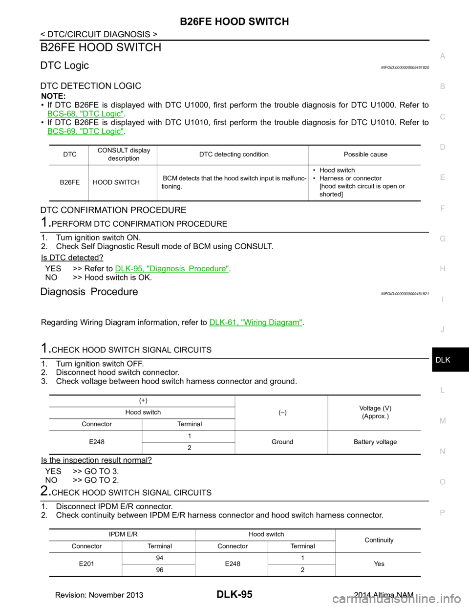
B26FE HOOD SWITCH
DTC LogicINFOID:0000000009461820
DTC DETECTION LOGIC
NOTE:
• If DTC B26FE is displayed with DTC U1000, firs t perform the trouble diagnosis for DTC U1000. Refer to
BCS-68, "DTC Logic"
.
• If DTC B26FE is displayed with DTC U1010, firs t perform the trouble diagnosis for DTC U1010. Refer to
BCS-69, "DTC Logic"
.
DTC CONFIRMATION PROCEDURE
1.PERFORM DTC CONFIRMATION PROCEDURE
1. Turn ignition switch ON.
2. Check Self Diagnostic Result mode of BCM using CONSULT.
Is DTC detected?
YES >> Refer to DLK-95, "Diagnosis Procedure".
NO >> Hood switch is OK.
Diagnosis ProcedureINFOID:0000000009461821
Regarding Wiring Diagram information, refer to DLK-61, "Wiring Diagram".
1.CHECK HOOD SWITCH SIGNAL CIRCUITS
1. Turn ignition switch OFF.
2. Disconnect hood switch connector.
3. Check voltage between hood switch harness connector and ground.
Is the inspection result normal?
YES >> GO TO 3.
NO >> GO TO 2.
2.CHECK HOOD SWITCH SIGNAL CIRCUITS
1. Disconnect IPDM E/R connector.
2. Check continuity between IPDM E/R har ness connector and hood switch harness connector.
DTCCONSULT display
description DTC detecting condition Possible cause
B26FE HOOD SWITCH BCM detects that the hood switch input is malfunc-
tioning. • Hood switch
• Harness or connector
[hood switch circuit is open or
shorted]
(+)
(–)Voltage (V)
(Approx.)
Hood switch
Connector Terminal
E248 1
Ground Battery voltage
2
IPDM E/R Hood switch Continuity
Connector Terminal Connector Terminal
E201 94
E248 1
Ye s
96 2
Revision: November 20132014 Altima NAMRevision: November 20132014 Altima NAM
Page 978 of 4801
DLK-210
< REMOVAL AND INSTALLATION >
TRUNK LID
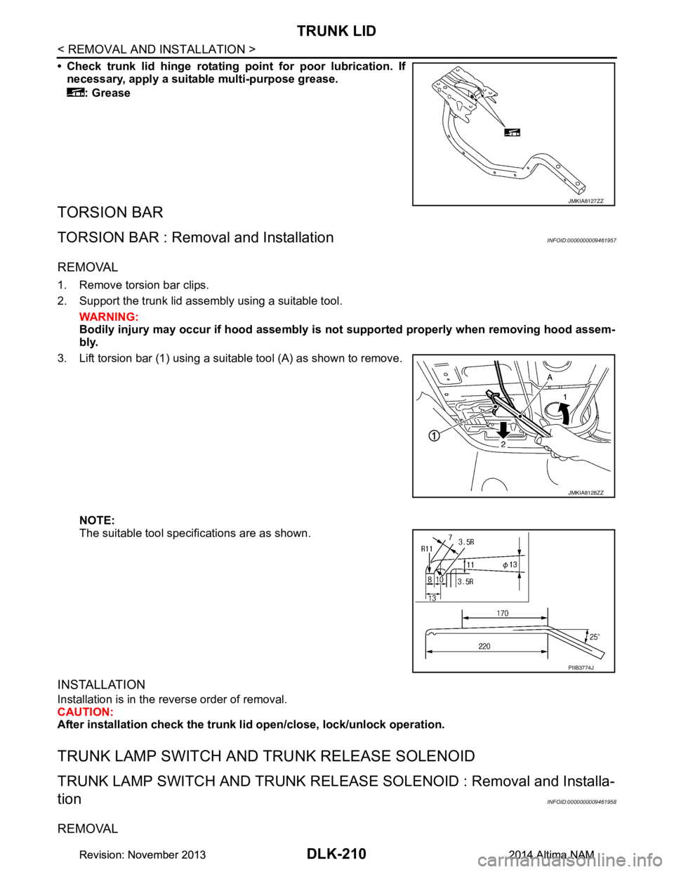
• Check trunk lid hinge rotating point for poor lubrication. If
necessary, apply a suitable multi-purpose grease.
: Grease
TORSION BAR
TORSION BAR : Remova l and InstallationINFOID:0000000009461957
REMOVAL
1. Remove torsion bar clips.
2. Support the trunk lid assembly using a suitable tool. WARNING:
Bodily injury may occur if hood assembly is not supported properly when removing hood assem-
bly.
3. Lift torsion bar (1) using a suitable tool (A) as shown to remove.
NOTE:
The suitable tool specifications are as shown.
INSTALLATION
Installation is in the reverse order of removal.
CAUTION:
After installation check the trunk li d open/close, lock/unlock operation.
TRUNK LAMP SWITCH AND TRUNK RELEASE SOLENOID
TRUNK LAMP SWITCH AND TRUNK RELEASE SOLENOID : Removal and Installa-
tion
INFOID:0000000009461958
REMOVAL
JMKIA8127ZZ
JMKIA8128ZZ
PIIB3774J
Revision: November 20132014 Altima NAMRevision: November 20132014 Altima NAM
Page 982 of 4801
DLK-214
< REMOVAL AND INSTALLATION >
FUEL FILLER LID OPENER
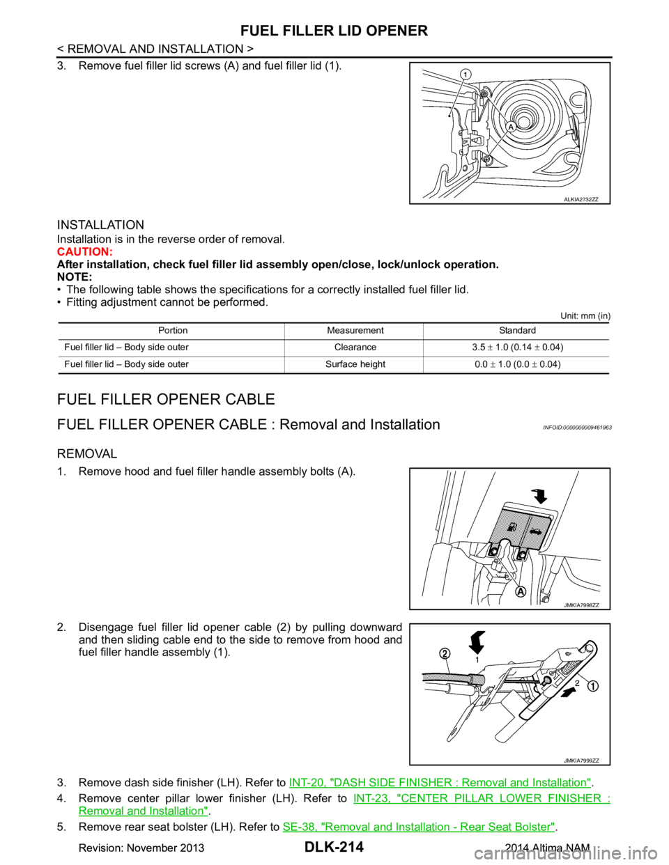
3. Remove fuel filler lid screws (A) and fuel filler lid (1).
INSTALLATION
Installation is in the reverse order of removal.
CAUTION:
After installation, check fuel filler li d assembly open/close, lock/unlock operation.
NOTE:
• The following table shows the specifications for a correctly installed fuel filler lid.
• Fitting adjustment cannot be performed.
Unit: mm (in)
FUEL FILLER OP ENER CABLE
FUEL FILLER OPENER CABLE : Removal and InstallationINFOID:0000000009461963
REMOVAL
1. Remove hood and fuel filler handle assembly bolts (A).
2. Disengage fuel filler lid opener cable (2) by pulling downward and then sliding cable end to the side to remove from hood and
fuel filler handle assembly (1).
3. Remove dash side finisher (LH). Refer to INT-20, "DASH SIDE FINISHER : Removal and Installation"
.
4. Remove center pillar lower finisher (LH). Refer to INT-23, "CENTER PILLAR LOWER FINISHER :
Removal and Installation".
5. Remove rear seat bolster (LH). Refer to SE-38, "Removal and Installation - Rear Seat Bolster"
.
ALKIA2732ZZ
Portion Measurement Standard
Fuel filler lid – Body side outer Clearance 3.5 ± 1.0 (0.14 ± 0.04)
Fuel filler lid – Body side outer Surface height 0.0 ± 1.0 (0.0 ± 0.04)
JMKIA7998ZZ
JMKIA7999ZZ
Revision: November 20132014 Altima NAMRevision: November 20132014 Altima NAM
Page 1170 of 4801
![NISSAN TEANA 2014 Service Manual
EC-170
< BASIC INSPECTION >[QR25DE]
BASIC INSPECTION
BASIC INSPECTION
Work ProcedureINFOID:0000000009462129
1.INSPECTION START
1. Check service records for any recent repairs that ma y indicate a rel NISSAN TEANA 2014 Service Manual
EC-170
< BASIC INSPECTION >[QR25DE]
BASIC INSPECTION
BASIC INSPECTION
Work ProcedureINFOID:0000000009462129
1.INSPECTION START
1. Check service records for any recent repairs that ma y indicate a rel](/img/5/57390/w960_57390-1169.png)
EC-170
< BASIC INSPECTION >[QR25DE]
BASIC INSPECTION
BASIC INSPECTION
Work ProcedureINFOID:0000000009462129
1.INSPECTION START
1. Check service records for any recent repairs that ma y indicate a related malfunction, or a current need for
scheduled maintenance.
2. Open engine hood and check the following:
- Harness connectors for improper connections
- Wiring harness for improper connections, pinches and cut
- Vacuum hoses for splits, kinks and improper connections
- Hoses and ducts for leaks
- Air cleaner clogging
- Gasket
3. Confirm that electrical or mechanical loads are not applied.
- Headlamp switch is OFF.
- Air conditioner switch is OFF.
- Rear window defogger switch is OFF.
- Steering wheel is in the straight-ahead position, etc.
4. Start engine and warm it up until engine coolant temperature indicator points the middle of gauge.
Ensure engine stays below 1,000 rpm.
5. Run engine at about 2,000 rpm for about 2 minutes under no load.
6. Make sure that no DTC is displayed with CONSULT or GST.
Is any DTC detected?
YES >> GO TO 2.
NO >> GO TO 3.
2.REPAIR OR REPLACE
Repair or replace components as necessary according to corresponding Diagnostic Procedure.
>> GO TO 3.
3.CHECK TARGET IDLE SPEED
1. Run engine at about 2,000 rpm for about 2 minutes under no load.
SEF983U
SEF976U
SEF977U
Revision: November 20132014 Altima NAMRevision: November 20132014 Altima NAM