fuel pressure NISSAN TEANA 2014 Owner's Manual
[x] Cancel search | Manufacturer: NISSAN, Model Year: 2014, Model line: TEANA, Model: NISSAN TEANA 2014Pages: 4801, PDF Size: 51.2 MB
Page 1022 of 4801
EC-22
< SYSTEM DESCRIPTION >[QR25DE]
COMPONENT PARTS
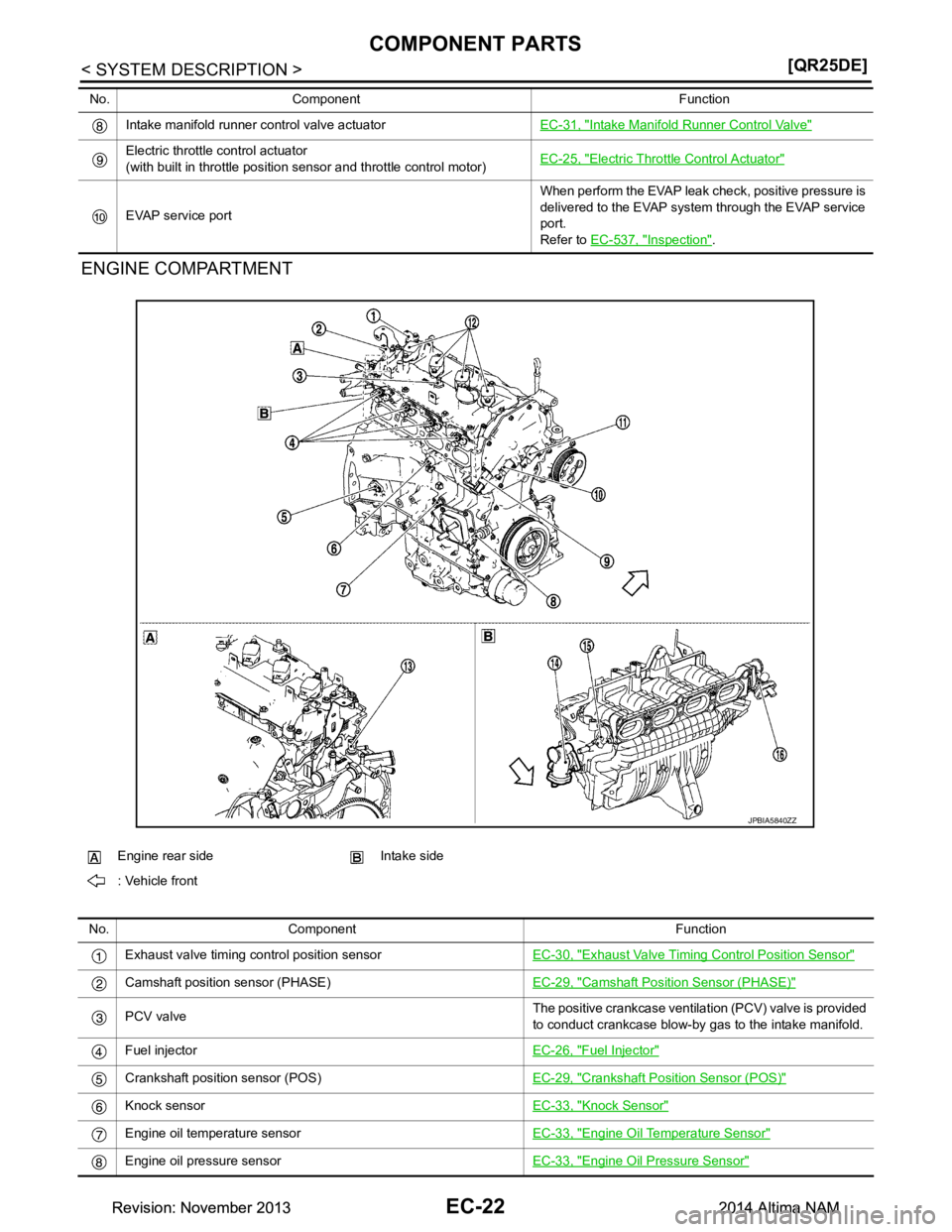
ENGINE COMPARTMENT
Intake manifold runner control valve actuator
EC-31, "Intake Manifold Runner Control Valve"
Electric throttle control actuator
(with built in throttle position sensor and throttle control motor) EC-25, "Electric Thrott
le Control Actuator"
EVAP service port When perform the EVAP leak check, positive pressure is
delivered to the EVAP system through the EVAP service
port.
Refer to EC-537, "Inspection"
.
No. Component Function
JPBIA5840ZZ
Engine rear side Intake side
: Vehicle front
No. Component Function
Exhaust valve timing control position sensor EC-30, "Exhaust Valve Timing Control Position Sensor"
Camshaft position sensor (PHASE)EC-29, "Camshaft Position Sensor (PHASE)"
PCV valveThe positive crankcase ventilation (PCV) valve is provided
to conduct crankcase blow-by gas to the intake manifold.
Fuel injector EC-26, "Fuel Injector"
Crankshaft position sensor (POS)EC-29, "Crankshaft Position Sensor (POS)"
Knock sensorEC-33, "Knock Sensor"
Engine oil temperature sensorEC-33, "Engine Oil Temperature Sensor"
Engine oil pressure sensorEC-33, "Engine Oil Pressure Sensor"
Revision: November 20132014 Altima NAMRevision: November 20132014 Altima NAM
Page 1024 of 4801
EC-24
< SYSTEM DESCRIPTION >[QR25DE]
COMPONENT PARTS
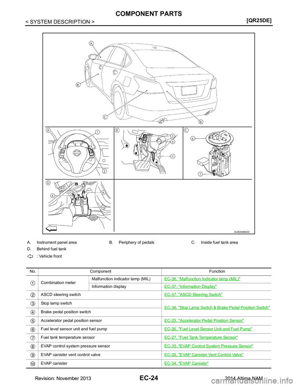
A. Instrument panel area B. Periphery of pedals C. Inside fuel tank area
D. Behind fuel tank
: Vehicle front
No. Component Function Combination meter Malfunction indicator lamp (MIL)
EC-36, "Malfunction Indicator lamp (MIL)"
Information displayEC-37, "Information Display"
ASCD steering switch EC-37, "ASCD Steering Switch"
Stop lamp switch
EC-36, "Stop Lamp Switch & Brake Pedal Position Switch"
Brake pedal position switch
Accelerator pedal position sensor EC-25, "Accelerator Pedal Position Sensor"
Fuel level sensor unit and fuel pumpEC-26, "Fuel Level Sensor Unit and Fuel Pump"
Fuel tank temperature sensorEC-27, "Fuel Tank Temperature Sensor"
EVAP control system pressure sensorEC-35, "EVAP Control System Pressure Sensor"
EVAP canister vent control valve EC-35, "EVAP Canister Vent Control Valve"
EVAP canisterEC-34, "EVAP Canister"
ALBIA0806ZZ
Revision: November 20132014 Altima NAMRevision: November 20132014 Altima NAM
Page 1034 of 4801
EC-34
< SYSTEM DESCRIPTION >[QR25DE]
COMPONENT PARTS
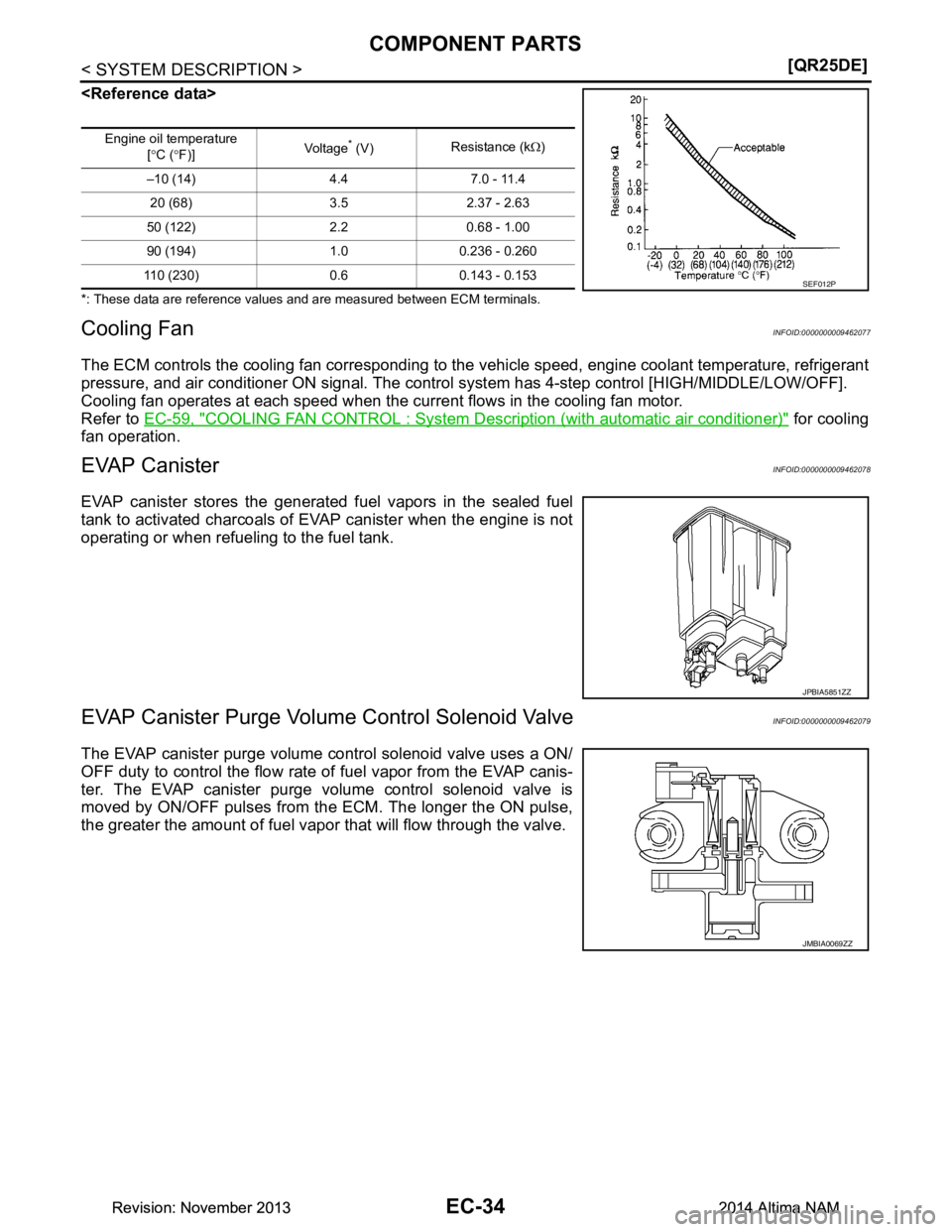
*: These data are reference values and are measured between ECM terminals.
Cooling FanINFOID:0000000009462077
The ECM controls the cooling fan corresponding to the
vehicle speed, engine coolant temperature, refrigerant
pressure, and air conditioner ON signal. The control system has 4-step control [HIGH/MIDDLE/LOW/OFF].
Cooling fan operates at each speed when the current flows in the cooling fan motor.
Refer to EC-59, "COOLING FAN CONTROL : System De scription (with automatic air conditioner)"
for cooling
fan operation.
EVAP CanisterINFOID:0000000009462078
EVAP canister stores the generat ed fuel vapors in the sealed fuel
tank to activated charcoals of EVAP canister when the engine is not
operating or when refueling to the fuel tank.
EVAP Canister Purge Volume Control Solenoid ValveINFOID:0000000009462079
The EVAP canister purge volume control solenoid valve uses a ON/
OFF duty to control the flow rate of fuel vapor from the EVAP canis-
ter. The EVAP canister purge volume control solenoid valve is
moved by ON/OFF pulses from the ECM. The longer the ON pulse,
the greater the amount of fuel vapor that will flow through the valve.
Engine oil temperature
[° C ( °F)] Vol tag e* (V)
Resistance (k
Ω)
–10 (14) 4.4 7.0 - 11.4 20 (68) 3.5 2.37 - 2.63
50 (122) 2.2 0.68 - 1.00
90 (194) 1.0 0.236 - 0.260
110 (230) 0.6 0.143 - 0.153
SEF012P
JPBIA5851ZZ
JMBIA0069ZZ
Revision: November 20132014 Altima NAMRevision: November 20132014 Altima NAM
Page 1035 of 4801
COMPONENT PARTSEC-35
< SYSTEM DESCRIPTION > [QR25DE]
C
D E
F
G H
I
J
K L
M A
EC
NP
O
EVAP Canister Vent Control ValveINFOID:0000000009462080
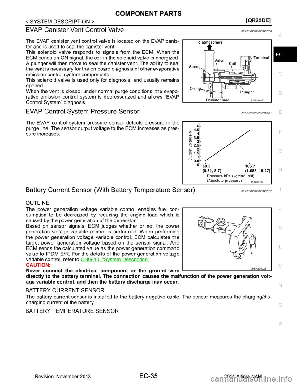
The EVAP canister vent control valve is located on the EVAP canis-
ter and is used to seal the canister vent.
This solenoid valve responds to signals from the ECM. When the
ECM sends an ON signal, the coil in the solenoid valve is energized.
A plunger will then move to seal the canister vent. The ability to seal
the vent is necessary for the on board diagnosis of other evaporative
emission control system components.
This solenoid valve is used only for diagnosis, and usually remains
opened.
When the vent is closed, under normal purge conditions, the evapo-
rative emission control system is depressurized and allows “EVAP
Control System” diagnosis.
EVAP Control System Pressure SensorINFOID:0000000009462081
The EVAP control system pressure sensor detects pressure in the
purge line. The sensor output voltage to the ECM increases as pres-
sure increases.
Battery Current Sensor (With Battery Temperature Sensor)INFOID:0000000009462082
OUTLINE
The power generation voltage variable control enables fuel con-
sumption to be decreased by reducing the engine load which is
caused by the power generation of the generator.
Based on sensor signals, ECM judges whether or not the power
generation voltage variable contro l is performed. When performing
the power generation voltage variable control, ECM calculates the
target power generation voltage based on the sensor signal. And
ECM sends the calculated value as the power generation command
value to IPDM E/R. For the details of the power generation voltage
variable control, refer to CHG-10, "System Description"
.
CAUTION:
Never connect the electrical co mponent or the ground wire
directly to the battery terminal. The connection cau ses the malfunction of the power generation volt-
age variable control, and then the battery discharge may occur.
BATTERY CURRENT SENSOR
The battery current sensor is installed to the battery negative cable. The sensor measures the charging/dis-
charging current of the battery.
BATTERY TEMPERATURE SENSOR
PBIB1263E
PBIB3370E
JPBIA3262ZZ
Revision: November 20132014 Altima NAMRevision: November 20132014 Altima NAM
Page 1039 of 4801
STRUCTURE AND OPERATIONEC-39
< SYSTEM DESCRIPTION > [QR25DE]
C
D E
F
G H
I
J
K L
M A
EC
NP
O
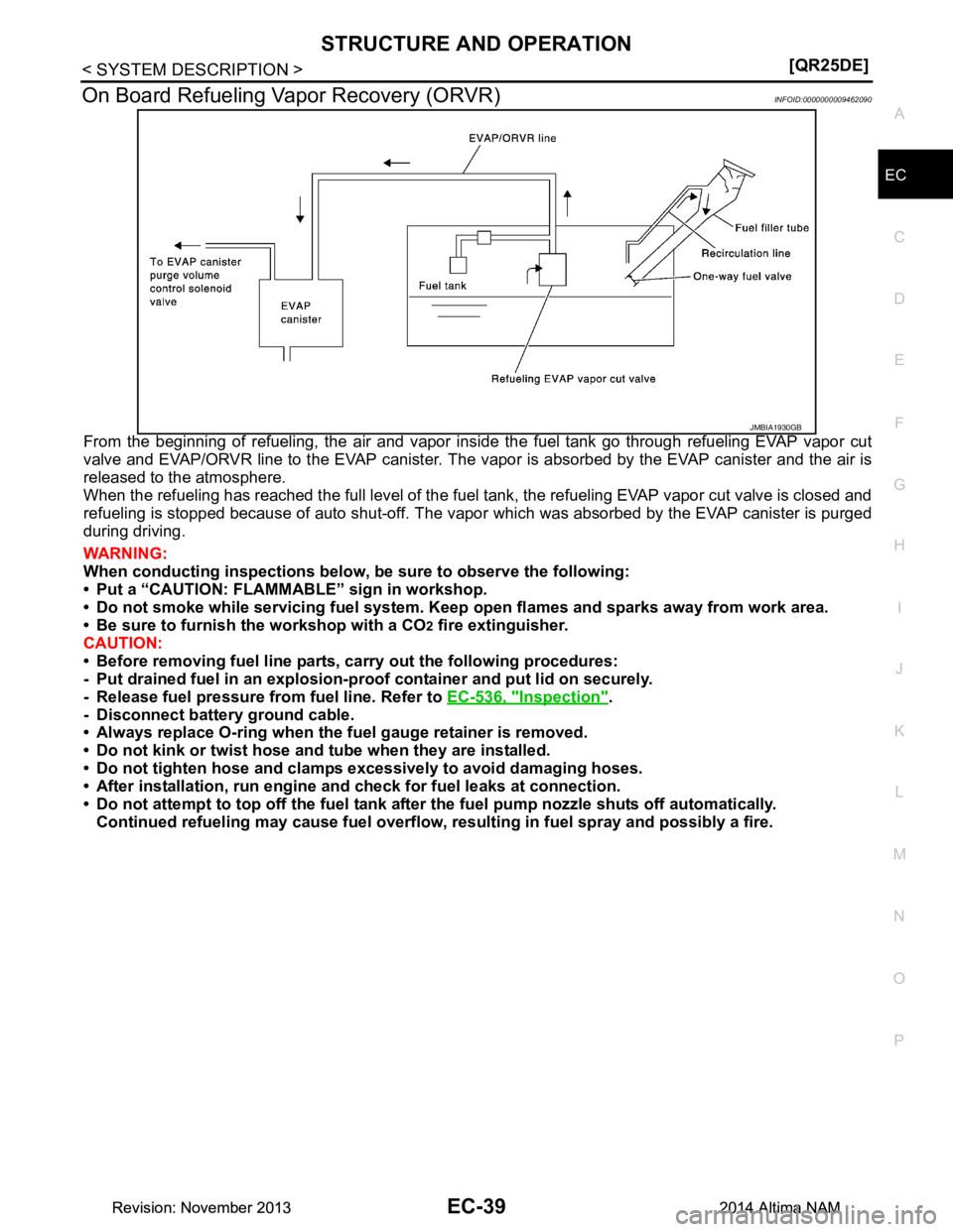
On Board Refueling Vapor Recovery (ORVR)INFOID:0000000009462090
From the beginning of refueling, the air and vapor insi
de the fuel tank go through refueling EVAP vapor cut
valve and EVAP/ORVR line to the EVAP canister. The v apor is absorbed by the EVAP canister and the air is
released to the atmosphere.
When the refueling has reached the full level of the fuel tank, the refueling EVAP vapor cut valve is closed and
refueling is stopped because of auto shut-off. The vapor which was absorbed by the EVAP canister is purged
during driving.
WARNING:
When conducting inspectio ns below, be sure to observe the following:
• Put a “CAUTION: FLAMMABL E” sign in workshop.
• Do not smoke while servicing fuel system. Keep open flames and sparks away from work area.
• Be sure to furnish the workshop with a CO
2 fire extinguisher.
CAUTION:
• Before removing fuel line parts, carry out the following procedures:
- Put drained fuel in an explosion-proof containe r and put lid on securely.
- Release fuel pressure from fuel line. Refer to EC-536, "Inspection"
.
- Disconnect battery ground cable.
• Always replace O-ring when the fu el gauge retainer is removed.
• Do not kink or twist hose and tube when they are installed.
• Do not tighten hose and clamps excessively to avoid damaging hoses.
• After installation, run engine a nd check for fuel leaks at connection.
• Do not attempt to top off the fuel tank after the fuel pump nozzle shuts off automatically.
Continued refueling may cause fuel overflow, r esulting in fuel spray and possibly a fire.
JMBIA1930GB
Revision: November 20132014 Altima NAMRevision: November 20132014 Altima NAM
Page 1041 of 4801
SYSTEMEC-41
< SYSTEM DESCRIPTION > [QR25DE]
C
D E
F
G H
I
J
K L
M A
EC
NP
O
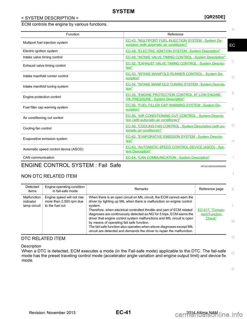
ECM controls the engine by various functions.
ENGINE CONTROL SYSTEM : Fail SafeINFOID:0000000009462092
NON DTC RELATED ITEM
DTC RELATED ITEM
Description
When a DTC is detected, ECM executes a mode (in the
Fail-safe mode) applicable to the DTC. The fail-safe
mode has the preset traveling control mode (accelera tor angle variation and engine output limit) and device fix
mode.
Function Reference
Multiport fuel injection system EC-43, "MULTIPORT FUEL INJECTION SYSTEM : System De-
scription (with automatic air conditioner)"
Electric ignition system
EC-48, "ELECTRIC IGNITION SYSTEM : System Description"
Intake valve timing control EC-49, "INTAKE VALVE TIMING CONTROL : System Description"
Exhaust valve timing control EC-52, "EXHAUST VALVE TIMING
CONTROL : System Descrip-tion"
Intake manifold runner control EC-53, "INTAKE MANIFOLD RUNNER CONTROL : System De-scription"
Intake manifold tuning system
EC-54, "INTAKE MANIFOLD TUNI
NG SYSTEM : System Descrip-tion"
Engine protection control EC-55, "ENGINE PROTECTION CONTROL AT LOW ENGINE OIL PRESSURE : System Description"
Fuel filler cap warning systemEC-56, "FUEL FILLER CAP WARNING SYSTEM : System De-scription"
Air conditioning cut control
EC-56, "AIR CONDITIONING CUT CONTROL : System Descrip-tion (with automatic air conditioner)"
Cooling fan controlEC-59, "COOLING FAN CONTROL :
System Description (with au-tomatic air conditioner)"
Evaporative emission system EC-62, "EVAPORATIVE EMISSION
SYSTEM : System Descrip-tion"
Automatic speed control device (ASCD) EC-63, "AUTOMATIC SPEED CONTROL DEVICE (ASCD) : Sys-tem Description"
CAN communication
EC-64, "CAN COMMUNICATION : System Description"
Detected
items Engine operating condition
in fail-safe mode Remarks Reference page
Malfunction
indicator
lamp circuit Engine speed will not rise
more than 2,500 rpm due
to the fuel cut When there is an open circuit on MIL circuit, the ECM cannot warn the
driver by lighting up MIL when there is malfunction on engine control
system.
Therefore, when electrical controlled throttle and part of ECM related
diagnoses are continuously detected as NG for 5 trips, ECM warns the
driver that engine control system malfunctions and MIL circuit is open
by means of operating fail safe function.
The fail safe function also operates when above diagnoses except MIL
circuit are detected and demands the driver to repair the malfunction. EC-517, "Compo-
nent Function
Check"
Revision: November 20132014 Altima NAMRevision: November 20132014 Altima NAM
Page 1042 of 4801
EC-42
< SYSTEM DESCRIPTION >[QR25DE]
SYSTEM
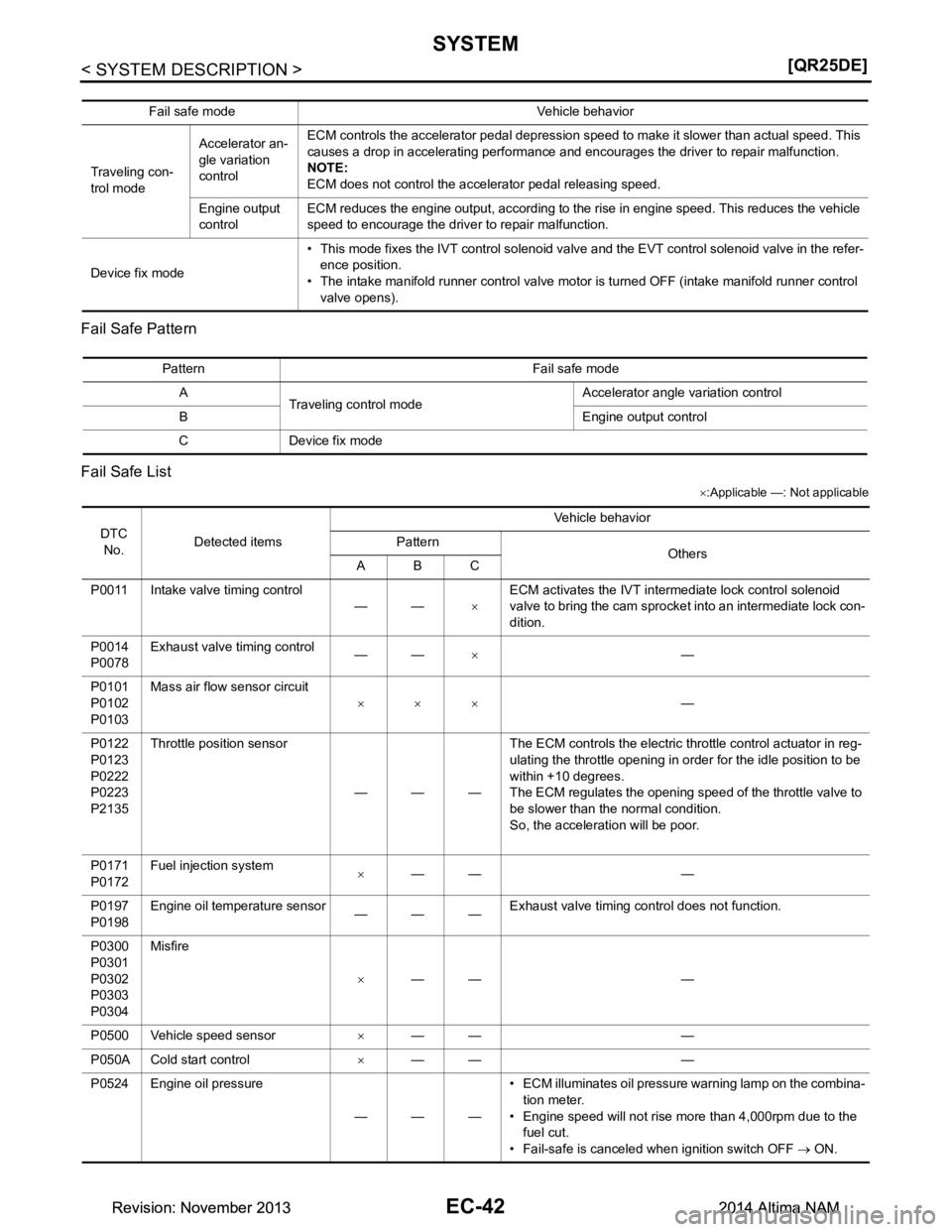
Fail Safe Pattern
Fail Safe List
× :Applicable —: Not applicable
Fail safe mode Vehicle behavior
Traveling con-
trol mode Accelerator an-
gle variation
control ECM controls the accelerator pedal depression speed to make it slower than actual speed. This
causes a drop in accelerating performance and encourages the driver to repair malfunction.
NOTE:
ECM does not control the accelerator pedal releasing speed.
Engine output
control ECM reduces the engine output, according to the rise in engine speed. This reduces the vehicle
speed to encourage the driver to repair malfunction.
Device fix mode • This mode fixes the IVT control solenoid valve and the EVT control solenoid valve in the refer-
ence position.
• The intake manifold runner control valve motor is turned OFF (intake manifold runner control valve opens).
Pattern Fail safe mode
A Traveling control mode Accelerator angle variation control
B Engine output control
C Device fix mode
DTC No. Detected items Vehicle behavior
Pattern Others
ABC
P0011 Intake valve timing control ——×ECM activates the IVT intermediate lock control solenoid
valve to bring the cam sprocket into an intermediate lock con-
dition.
P0014
P0078 Exhaust valve timing control
——× —
P0101
P0102
P0103 Mass air flow sensor circuit
××× —
P0122
P0123
P0222
P0223
P2135 Throttle position sensor
———The ECM controls the electric throttle control actuator in reg-
ulating the throttle opening in order for the idle position to be
within +10 degrees.
The ECM regulates the opening speed of the throttle valve to
be slower than the normal condition.
So, the acceleration will be poor.
P0171
P0172 Fuel injection system
×—— —
P0197
P0198 Engine oil temperature sensor
———Exhaust valve timing control does not function.
P0300
P0301
P0302
P0303
P0304 Misfire
×—— —
P0500 Vehicle speed sensor ×—— —
P050A Cold start control ×—— —
P0524 Engine oil pressure
———• ECM illuminates oil pressure warning lamp on the combina-
tion meter.
• Engine speed will not rise more than 4,000rpm due to the
fuel cut.
• Fail-safe is canceled when ignition switch OFF → ON.
Revision: November 20132014 Altima NAMRevision: November 20132014 Altima NAM
Page 1055 of 4801
SYSTEMEC-55
< SYSTEM DESCRIPTION > [QR25DE]
C
D E
F
G H
I
J
K L
M A
EC
NP
O
Intake Manifold Tuning Valve Operating Condition
ECM opens the intake manifold tuning valve when all of the following conditions are satisfied.
• Engine speed: 5,000 rpm or more
• Engine coolant temperature: -30 °C (-22 °F) or more
• Battery voltage: 16 V or less
ENGINE PROTECTION CONTROL AT LOW ENGINE OIL PRESSURE
ENGINE PROTECTION CONTROL AT LOW ENGINE OIL PRESSURE : System De-
scription
INFOID:0000000009462100
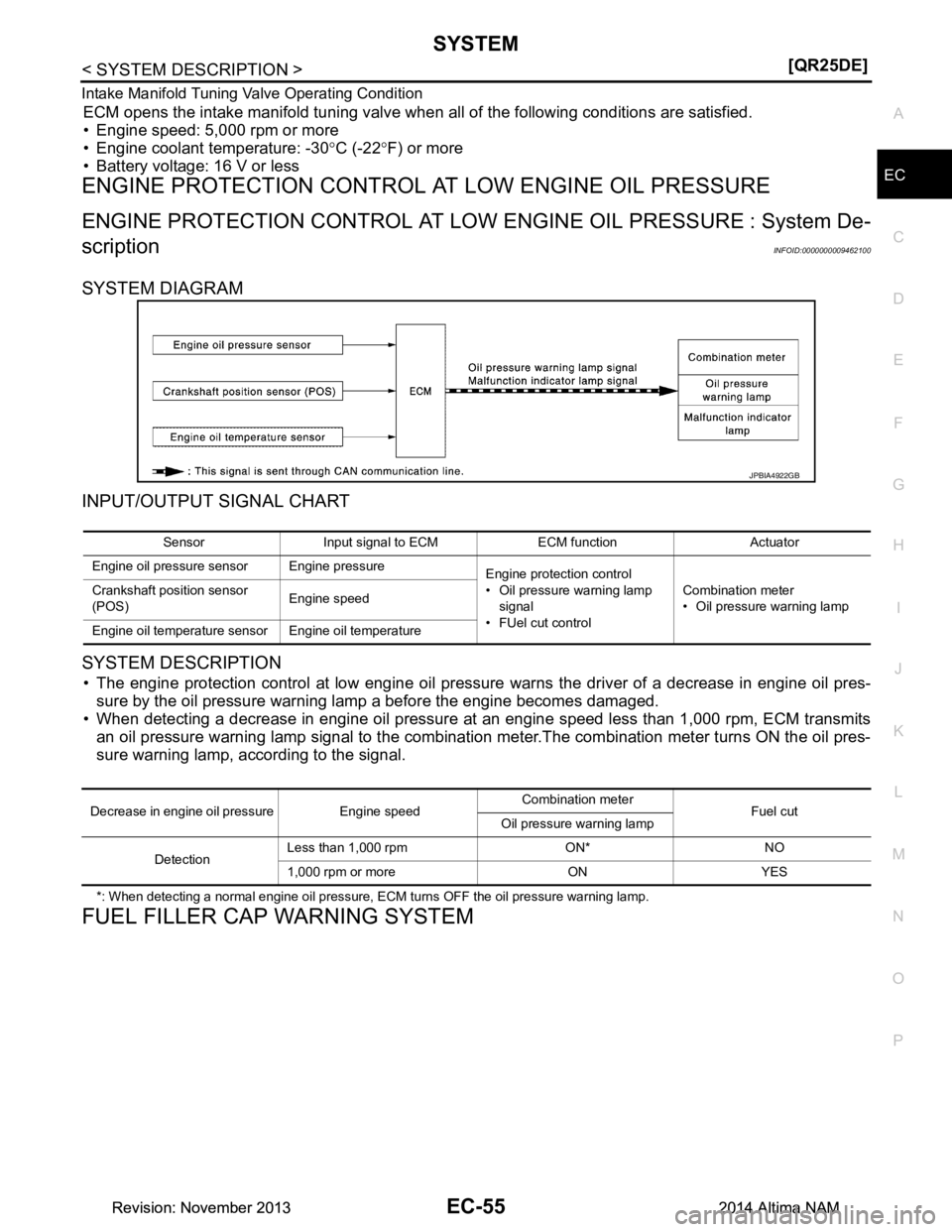
SYSTEM DIAGRAM
INPUT/OUTPUT SIGNAL CHART
SYSTEM DESCRIPTION
• The engine protection control at low engine oil pressure warns the driver of a decrease in engine oil pres-
sure by the oil pressure warning lamp a before the engine becomes damaged.
• When detecting a decrease in engine oil pressure at an engine speed less than 1,000 rpm, ECM transmits an oil pressure warning lamp signal to the combination meter.The combination meter turns ON the oil pres-
sure warning lamp, according to the signal.
*: When detecting a normal engine oil pressure, ECM turns OFF the oil pressure warning lamp.
FUEL FILLER CAP WARNING SYSTEM
JPBIA4922GB
Sensor Input signal to ECM ECM function Actuator
Engine oil pressure sensor Engine pressure Engine protection control
• Oil pressure warning lamp
signal
•FUel cut control Combination meter
• Oil pressure warning lamp
Crankshaft position sensor
(POS) Engine speed
Engine oil temperature sensor Engine oil temperature
Decrease in engine oil pressure Engine speed Combination meter
Fuel cut
Oil pressure warning lamp
Detection Less than 1,000 rpm ON* NO
1,000 rpm or more ON YES
Revision: November 20132014 Altima NAMRevision: November 20132014 Altima NAM
Page 1062 of 4801
EC-62
< SYSTEM DESCRIPTION >[QR25DE]
SYSTEM
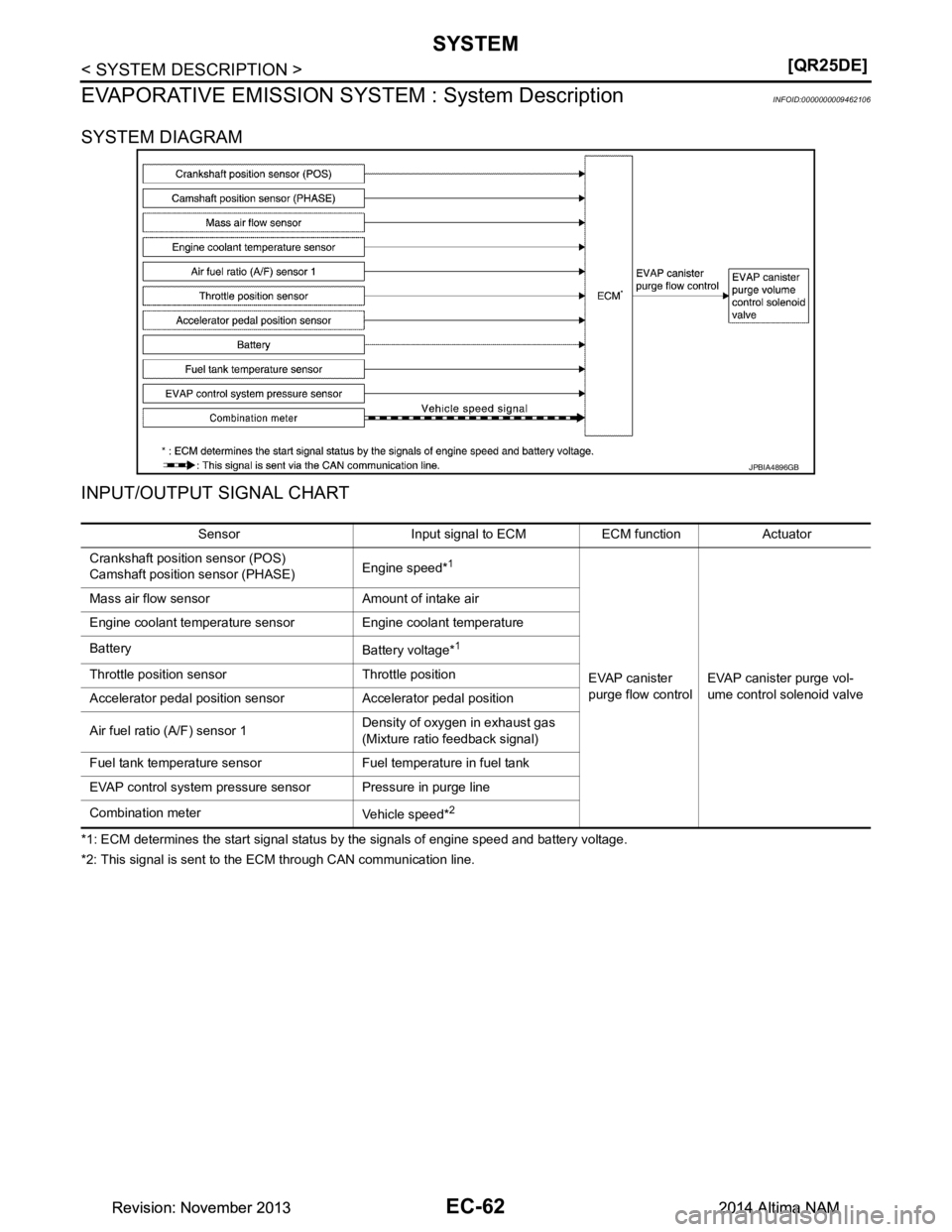
EVAPORATIVE EMISSION SYSTEM : System Description
INFOID:0000000009462106
SYSTEM DIAGRAM
INPUT/OUTPUT SIGNAL CHART
*1: ECM determines the start signal status by the signals of engine speed and battery voltage.
*2: This signal is sent to the ECM through CAN communication line.
JPBIA4896GB
Sensor Input signal to ECM ECM function Actuator
Crankshaft position sensor (POS)
Camshaft position sensor (PHASE) Engine speed*
1
EVAP canister
purge flow control EVAP canister purge vol-
ume control solenoid valve
Mass air flow sensor Amount of intake air
Engine coolant temperature sensor Engine coolant temperature
Battery Battery voltage*
1
Throttle position sensor Throttle position
Accelerator pedal position sensor Accelerator pedal position
Air fuel ratio (A/F) sensor 1 Density of oxygen in exhaust gas
(Mixture ratio fe edback signal)
Fuel tank temperature sensor Fuel temperature in fuel tank
EVAP control system pressure sensor Pressure in purge line
Combination meter Vehicle speed*
2
Revision: November 20132014 Altima NAMRevision: November 20132014 Altima NAM
Page 1080 of 4801
EC-80
< SYSTEM DESCRIPTION >[QR25DE]
DIAGNOSIS SYSTEM (ECM)
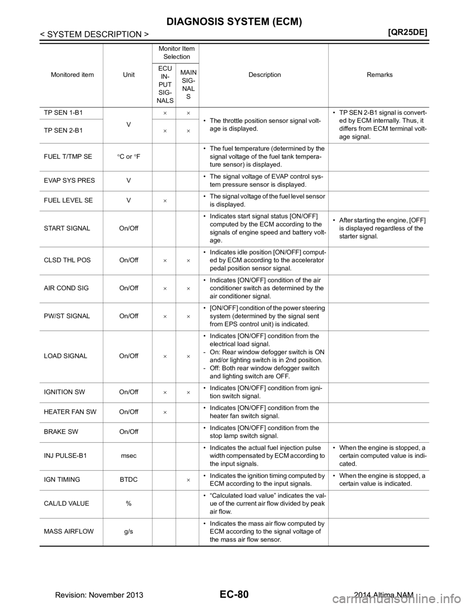
TP SEN 1-B1
V××
• The throttle position sensor signal volt-age is displayed. • TP SEN 2-B1 signal is convert-
ed by ECM internally. Thus, it
differs from ECM terminal volt-
age signal.
TP SEN 2-B1
××
FUEL T/TMP SE °C or °F • The fuel temperature (determined by the
signal voltage of the fuel tank tempera-
ture sensor) is displayed.
EVAP SYS PRES V • The signal voltage of EVAP control sys-
tem pressure sensor is displayed.
FUEL LEVEL SE V ו The signal voltage of the fuel level sensor
is displayed.
START SIGNAL On/Off • Indicates start signal status [ON/OFF]
computed by the ECM according to the
signals of engine speed and battery volt-
age. • After starting the engine, [OFF]
is displayed regardless of the
starter signal.
CLSD THL POS On/Off ×ו Indicates idle position [ON/OFF] comput-
ed by ECM according to the accelerator
pedal position sensor signal.
AIR COND SIG On/Off ×ו Indicates [ON/OFF] condition of the air
conditioner switch as determined by the
air conditioner signal.
PW/ST SIGNAL On/Off ×ו [ON/OFF] condition of the power steering
system (determined by the signal sent
from EPS control unit) is indicated.
LOAD SIGNAL On/Off ×ו Indicates [ON/OFF] condition from the
electrical load signal.
- On: Rear window defogger switch is ON and/or lighting switch is in 2nd position.
- Off: Both rear window defogger switch
and lighting switch are OFF.
IGNITION SW On/Off ×ו Indicates [ON/OFF] condition from igni-
tion switch signal.
HEATER FAN SW On/Off ו Indicates [ON/OFF] condition from the
heater fan switch signal.
BRAKE SW On/Off • Indicates [ON/OFF] condition from the
stop lamp switch signal.
INJ PULSE-B1 msec • Indicates the actual fuel injection pulse
width compensated by ECM according to
the input signals. • When the engine is stopped, a
certain computed value is indi-
cated.
IGN TIMING BTDC ו Indicates the ignition timing computed by
ECM according to the input signals. • When the engine is stopped, a
certain value is indicated.
CAL/LD VALUE % • “Calculated load value” indicates the val-
ue of the current air flow divided by peak
air flow.
MASS AIRFLOW g/s • Indicates the mass air flow computed by
ECM according to the signal voltage of
the mass air flow sensor.
Monitored item Unit
Monitor Item
Selection
Description Remarks
ECU
IN-
PUT
SIG-
NALS MAIN
SIG-
NAL S
Revision: November 20132014 Altima NAMRevision: November 20132014 Altima NAM