sensor NISSAN TEANA 2014 Manual Online
[x] Cancel search | Manufacturer: NISSAN, Model Year: 2014, Model line: TEANA, Model: NISSAN TEANA 2014Pages: 4801, PDF Size: 51.2 MB
Page 272 of 4801
![NISSAN TEANA 2014 Manual Online
BRC-126
< REMOVAL AND INSTALLATION >[VDC/TCS/ABS]
WHEEL SENSOR
caught in the surface of the mating surface for the
sensor rotor. Fix as necessary and then install the
wheel sensor.
REMOVAL
1. Remove NISSAN TEANA 2014 Manual Online
BRC-126
< REMOVAL AND INSTALLATION >[VDC/TCS/ABS]
WHEEL SENSOR
caught in the surface of the mating surface for the
sensor rotor. Fix as necessary and then install the
wheel sensor.
REMOVAL
1. Remove](/img/5/57390/w960_57390-271.png)
BRC-126
< REMOVAL AND INSTALLATION >[VDC/TCS/ABS]
WHEEL SENSOR
caught in the surface of the mating surface for the
sensor rotor. Fix as necessary and then install the
wheel sensor.
REMOVAL
1. Remove the rear wheels and tires using power tool. Refer to WT-55, "Adjustment".
2. Disconnect the rear wheel sensor harness connector.
3. Remove the rear wheel sensor from the rear wheel sensor brackets and clips.
4. Remove the rear wheel sensor hold down bolt and remove the rear wheel senor.
INSTALLATION
Installation is in the reverse order of removal.
CAUTION:
Do not twist rear wheel senso r harness when installing rear
wheel sensor. Check that grommet (2) is fully inserted to
bracket (1). Check that rear wheel sensor harness is not twisted
after installation.
JPFIC0209ZZ
Revision: November 20132014 Altima NAMRevision: November 20132014 Altima NAM
Page 273 of 4801
![NISSAN TEANA 2014 Manual Online
SENSOR ROTORBRC-127
< REMOVAL AND INSTALLATION > [VDC/TCS/ABS]
C
D E
G H
I
J
K L
M A
B
BRC
N
O P
SENSOR ROTOR
Removal and Installation - Front Sensor RotorINFOID:0000000009463850
The front wheel se NISSAN TEANA 2014 Manual Online
SENSOR ROTORBRC-127
< REMOVAL AND INSTALLATION > [VDC/TCS/ABS]
C
D E
G H
I
J
K L
M A
B
BRC
N
O P
SENSOR ROTOR
Removal and Installation - Front Sensor RotorINFOID:0000000009463850
The front wheel se](/img/5/57390/w960_57390-272.png)
SENSOR ROTORBRC-127
< REMOVAL AND INSTALLATION > [VDC/TCS/ABS]
C
D E
G H
I
J
K L
M A
B
BRC
N
O P
SENSOR ROTOR
Removal and Installation - Front Sensor RotorINFOID:0000000009463850
The front wheel sensor rotor is an integral part of the wheel hub and bearing assembly and cannot be disas-
sembled. Refer to FAX-8, "Removal and Installation"
.
Removal and Installation - Rear Sensor RotorINFOID:0000000009463851
The rear wheel sensor rotor is an integral part of the wheel hub and bearing assembly and cannot be disas-
sembled. Refer to RAX-6, "Removal and Installation"
.
Revision: November 20132014 Altima NAMRevision: November 20132014 Altima NAM
Page 275 of 4801
![NISSAN TEANA 2014 Manual Online
ABS ACTUATOR AND ELECTRIC UNIT (CONTROL UNIT)BRC-129
< REMOVAL AND INSTALLATION > [VDC/TCS/ABS]
C
D E
G H
I
J
K L
M A
B
BRC
N
O P
3. Remove the power steering line hold down bracket.
4. Disconnect NISSAN TEANA 2014 Manual Online
ABS ACTUATOR AND ELECTRIC UNIT (CONTROL UNIT)BRC-129
< REMOVAL AND INSTALLATION > [VDC/TCS/ABS]
C
D E
G H
I
J
K L
M A
B
BRC
N
O P
3. Remove the power steering line hold down bracket.
4. Disconnect](/img/5/57390/w960_57390-274.png)
ABS ACTUATOR AND ELECTRIC UNIT (CONTROL UNIT)BRC-129
< REMOVAL AND INSTALLATION > [VDC/TCS/ABS]
C
D E
G H
I
J
K L
M A
B
BRC
N
O P
3. Remove the power steering line hold down bracket.
4. Disconnect ABS actuator and el ectric unit (control unit) harness connector and place aside.
5. Loosen brake tube flare nuts using a suitable tool, t hen remove brake tubes from ABS actuator and elec-
tric unit (control unit) and place aside. Refer to BRC-128, "Exploded View"
.
6. Remove the harness bracket bolt and place aside.
7. Remove ABS actuator and electric unit (control unit) and bracket as an assembly.
8. Remove bracket from ABS actuator and el ectric unit (control unit), if necessary.
INSTALLATION
Installation is in the reverse order of removal.
CAUTION:
If ABS actuator and electronic unit (control unit) is replaced, after installation, adjust position of steer-
ing angle sensor. Refer to BRC-58, "Work Procedure"
.
ALFIA0306ZZ
ALFIA0302ZZ
Revision: November 20132014 Altima NAMRevision: November 20132014 Altima NAM
Page 277 of 4801
![NISSAN TEANA 2014 Manual Online
YAW RATE/SIDE/DECEL G SENSORBRC-131
< REMOVAL AND INSTALLATION > [VDC/TCS/ABS]
C
D E
G H
I
J
K L
M A
B
BRC
N
O P
YAW RATE/SIDE/DECEL G SENSOR
Removal and InstallationINFOID:0000000009463855
The yaw NISSAN TEANA 2014 Manual Online
YAW RATE/SIDE/DECEL G SENSORBRC-131
< REMOVAL AND INSTALLATION > [VDC/TCS/ABS]
C
D E
G H
I
J
K L
M A
B
BRC
N
O P
YAW RATE/SIDE/DECEL G SENSOR
Removal and InstallationINFOID:0000000009463855
The yaw](/img/5/57390/w960_57390-276.png)
YAW RATE/SIDE/DECEL G SENSORBRC-131
< REMOVAL AND INSTALLATION > [VDC/TCS/ABS]
C
D E
G H
I
J
K L
M A
B
BRC
N
O P
YAW RATE/SIDE/DECEL G SENSOR
Removal and InstallationINFOID:0000000009463855
The yaw rate/side/decel G sensor is an integral part of the ABS actuator and electrical control unit (control
unit) and cannot be disassembled. Refer to BRC-128, "Removal and Installation"
.
Revision: November 20132014 Altima NAMRevision: November 20132014 Altima NAM
Page 278 of 4801
![NISSAN TEANA 2014 Manual Online
BRC-132
< REMOVAL AND INSTALLATION >[VDC/TCS/ABS]
STEERING ANGLE SENSOR
STEERING ANGLE SENSOR
Exploded ViewINFOID:0000000009463856
Removal and InstallationINFOID:0000000009463857
REMOVAL
1. Remove sp NISSAN TEANA 2014 Manual Online
BRC-132
< REMOVAL AND INSTALLATION >[VDC/TCS/ABS]
STEERING ANGLE SENSOR
STEERING ANGLE SENSOR
Exploded ViewINFOID:0000000009463856
Removal and InstallationINFOID:0000000009463857
REMOVAL
1. Remove sp](/img/5/57390/w960_57390-277.png)
BRC-132
< REMOVAL AND INSTALLATION >[VDC/TCS/ABS]
STEERING ANGLE SENSOR
STEERING ANGLE SENSOR
Exploded ViewINFOID:0000000009463856
Removal and InstallationINFOID:0000000009463857
REMOVAL
1. Remove spiral cable assembly. Refer to
SR-15, "Removal and Installation".
2. Remove the two screws and the steering angle sensor from spiral cable.
INSTALLATION
Installation is in the reverse order of removal.
CAUTION:
• Do not reuse steering angle sensor.
• Perform the neutral position adjustment of the steering angle sensor. Refer to BRC-58, "Work Proce-
dure".
1. Steering angle sensor A. Screw Front
ALFIA0235ZZ
Revision: November 20132014 Altima NAMRevision: November 20132014 Altima NAM
Page 281 of 4801

PRECAUTIONSBRM-3
< PRECAUTION >
C
D E
F
G H
I
J
L
M A
B
BRM
N
O P
PRECAUTION
PRECAUTIONS
Precaution for Supplemental Restraint System (SRS) "AIR BAG" and "SEAT BELT
PRE-TENSIONER"
INFOID:0000000009951573
The Supplemental Restraint System such as “A IR BAG” and “SEAT BELT PRE-TENSIONER”, used along
with a front seat belt, helps to reduce the risk or severi ty of injury to the driver and front passenger for certain
types of collision. Information necessary to service t he system safely is included in the SR and SB section of
this Service Manual.
WARNING:
• To avoid rendering the SRS inoper ative, which could increase the risk of personal injury or death in
the event of a collision which would result in air bag inflation, all maintenance must be performed by
an authorized NISSAN/INFINITI dealer.
• Improper maintenance, including in correct removal and installation of the SRS, can lead to personal
injury caused by unintentional act ivation of the system. For removal of Spiral Cable and Air Bag
Module, see the SR section.
• Do not use electrical test equipm ent on any circuit related to the SRS unless instructed to in this
Service Manual. SRS wiring harnesses can be identi fied by yellow and/or orange harnesses or har-
ness connectors.
PRECAUTIONS WHEN USING POWER TOOLS (AIR OR ELECTRIC) AND HAMMERS
WARNING:
• When working near the Airbag Diagnosis Sensor Un it or other Airbag System sensors with the Igni-
tion ON or engine running, DO NOT use air or el ectric power tools or strike near the sensor(s) with a
hammer. Heavy vibration could activate the sensor( s) and deploy the air bag(s), possibly causing
serious injury.
• When using air or electric power tools or hammers , always switch the Ignition OFF, disconnect the
battery and wait at least three mi nutes before performing any service.
Revision: November 20132014 Altima NAM
Page 343 of 4801

CCS-2
< PRECAUTION >
PRECAUTIONS
PRECAUTION
PRECAUTIONS
Precaution for Supplemental Restraint System (SRS) "AIR BAG" and "SEAT BELT
PRE-TENSIONER"
INFOID:0000000009951633
The Supplemental Restraint System such as “A IR BAG” and “SEAT BELT PRE-TENSIONER”, used along
with a front seat belt, helps to reduce the risk or severi ty of injury to the driver and front passenger for certain
types of collision. Information necessary to service the system safely is included in the SR and SB section of
this Service Manual.
WARNING:
• To avoid rendering the SRS inopera tive, which could increase the risk of personal injury or death in
the event of a collision which would result in air bag inflation, all maintenance must be performed by
an authorized NISS AN/INFINITI dealer.
• Improper maintenance, including in correct removal and installation of the SRS, can lead to personal
injury caused by unintent ional activation of the system. For re moval of Spiral Cable and Air Bag
Module, see the SR section.
• Do not use electrical test equipmen t on any circuit related to the SRS unless instructed to in this
Service Manual. SRS wiring harn esses can be identified by yellow and/or orange harnesses or har-
ness connectors.
PRECAUTIONS WHEN USING POWER TOOLS (AIR OR ELECTRIC) AND HAMMERS
WARNING:
• When working near the Airbag Diagnosis Sensor Unit or other Airbag System sensors with the Igni-
tion ON or engine running, DO NOT use air or electri c power tools or strike near the sensor(s) with a
hammer. Heavy vibration could activate the sensor( s) and deploy the air bag(s), possibly causing
serious injury.
• When using air or electric power tools or hammers , always switch the Ignition OFF, disconnect the
battery and wait at least three minutes before performing any service.
Revision: November 20132014 Altima NAM
Page 348 of 4801

CHG
PRECAUTIONSCHG-3
< PRECAUTION >
C
D E
F
G H
I
J
K L
B
A
O P
N
PRECAUTION
PRECAUTIONS
Precaution for Supplemental
Restraint System (SRS) "AIR BAG" and "SEAT BELT
PRE-TENSIONER"
INFOID:0000000009951598
The Supplemental Restraint System such as “A IR BAG” and “SEAT BELT PRE-TENSIONER”, used along
with a front seat belt, helps to reduce the risk or severi ty of injury to the driver and front passenger for certain
types of collision. Information necessary to service t he system safely is included in the SR and SB section of
this Service Manual.
WARNING:
• To avoid rendering the SRS inoper ative, which could increase the risk of personal injury or death in
the event of a collision which would result in air bag inflation, all maintenance must be performed by
an authorized NISSAN/INFINITI dealer.
• Improper maintenance, including in correct removal and installation of the SRS, can lead to personal
injury caused by unintentional act ivation of the system. For removal of Spiral Cable and Air Bag
Module, see the SR section.
• Do not use electrical test equipm ent on any circuit related to the SRS unless instructed to in this
Service Manual. SRS wiring harnesses can be identi fied by yellow and/or orange harnesses or har-
ness connectors.
PRECAUTIONS WHEN USING POWER TOOLS (AIR OR ELECTRIC) AND HAMMERS
WARNING:
• When working near the Airbag Diagnosis Sensor Un it or other Airbag System sensors with the Igni-
tion ON or engine running, DO NOT use air or el ectric power tools or strike near the sensor(s) with a
hammer. Heavy vibration could activate the sensor( s) and deploy the air bag(s), possibly causing
serious injury.
• When using air or electric power tools or hammers , always switch the Ignition OFF, disconnect the
battery and wait at least three mi nutes before performing any service.
Precaution for Power Generation Voltage Variable Control SystemINFOID:0000000009460643
CAUTION:
For this model, the battery current sensor that is in stalled to the battery cable at the negative terminal
measures the charging/discharging cu rrent of the battery, and performs various controls. If the electri-
cal component or the ground wire is connected direct ly to the battery terminal, the current other than
that being measured with the battery current sensor is charging to or discharging from the battery.
This condition causes the malfunction of the control, and then the battery discharge may occur. Do
not connect the electrical component or the gr ound wire directly to the battery terminal.
Revision: November 20132014 Altima NAMRevision: November 20132014 Altima NAM
Page 350 of 4801

CHG
COMPONENT PARTSCHG-5
< SYSTEM DESCRIPTION >
C
D E
F
G H
I
J
K L
B
A
O P
N
SYSTEM DESCRIPTION
COMPONENT PARTS
QR25DE
QR25DE : Component Parts LocationINFOID:0000000009460646
AWMIA1297GB
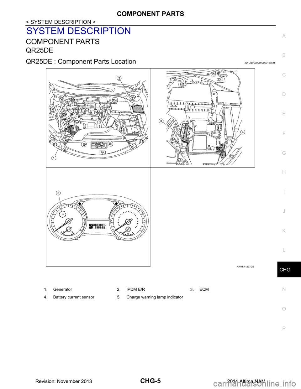
1. Generator 2. IPDM E/R 3. ECM
4. Battery current sensor 5. Charge warning lamp indicator
Revision: November 20132014 Altima NAMRevision: November 20132014 Altima NAM
Page 351 of 4801

CHG-6
< SYSTEM DESCRIPTION >
COMPONENT PARTS
QR25DE : Component Description
INFOID:0000000009460647
VQ35DE
Component part Description
Generator (IC regulator) The IC regulator controls the power generation voltage by the tar-
get power generation voltage based on the received PWM com-
mand signal.
When there is no PWM command signal, the generator performs
the normal power generation according to the characteristic of the
IC regulator.
ECM The battery current sensor detects the charging/discharging cur-
rent of the battery. The ECM judges the battery condition based on
this signal.
The ECM judges whether to request more output via the power
generation voltage variable control according to the battery condi-
tion.
When performing the power generation voltage variable control,
the ECM calculates the target power generation voltage according
to the battery condition and sends the calculated value as the pow-
er generation command value to the IPDM E/R.
IPDM E/R The IPDM E/R converts the received power generation command
value into a pulse width modulated (PWM) command signal and
sends it to the IC regulator.
Combination meter (c harge warning lamp) The IC regulator warning function activates to illuminate the
charge warning lamp if any of the following symptoms occur while
generator is operating:
·Excessive voltage is produced.
·No voltage is produced.
Battery current sensor The battery current sensor is located on the negative battery cable
terminal. The battery current sensor detects the charging/dis-
charging current of the battery and sends a voltage signal to the
ECM according to the current value detected.
Revision: November 20132014 Altima NAMRevision: November 20132014 Altima NAM