HAC NISSAN TEANA 2014 Service Manual
[x] Cancel search | Manufacturer: NISSAN, Model Year: 2014, Model line: TEANA, Model: NISSAN TEANA 2014Pages: 4801, PDF Size: 51.2 MB
Page 1 of 4801

A
B
C
D
E
F
G
H
I
J
K
L
M
N
P
O
QUICK REFERENCE INDEX
AGENERAL INFORMATIONGIGeneral Information
BENGINEEMEngine Mechanical
LUEngine Lubrication System
COEngine Cooling System
ECEngine Control System
FLFuel System
EXExhaust System
STRStarting System
ACCAccelerator Control System
CHYBRIDHBCHybrid Control System
DTRANSMISSION & DRIVE-LINECLClutch System
TMTransaxle & Transmission
DLNDriveline
FAXFront Axle
RAXRear Axle
ESUSPENSIONFSUFront Suspension
RSURear Suspension
SCSSuspension Control System
WTRoad Wheels & Tires
FBRAKESBRBrake System
PBParking Brake System
BRCBrake Control System
GSTEERINGSTSteering System
STCSteering Control System
HRESTRAINTSSBSeat Belt
SBCSeat Belt Control System
SRSRS Airbag
SRCSRS Airbag Control System
IVENTILATION, HEATER &
AIR CONDITIONERVTLVentilation System
HAHeater & Air Conditioning System
HACHeater & Air Conditioning Control System
JBODY INTERIORINTInterior
IPInstrument Panel
SESeat
ADPAutomatic Drive Positioner
KBODY EXTERIOR, DOORS, ROOF & VEHICLE
SECURITYDLKDoor & Lock
SECSecurity Control System
GWGlass & Window System
PWCPower Window Control System
RFRoof
EXTExterior
BRMBody Repair Manual
LDRIVER CONTROLSMIRMirrors
EXLExterior Lighting System
INLInterior Lighting System
WWWiper & Washer
DEFDefogger
HRNHorn
MELECTRICAL & POWER
CONTROLPWOPower Outlet
BCSBody Control System
LANLAN System
PCSPower Control System
CHGCharging System
PGPower Supply, Ground & Circuit Elements
NDRIVER INFORMATION &
MULTIMEDIAMWIMeter, Warning Lamp & Indicator
WCSWarning Chime System
SNSonar System
AVAudio, Visual & Navigation System
OCRUISE CONTROLCCSCruise Control System
DASDriver Assistance System
PMAINTENANCEMAMaintenance
All rights reserved. No part
of this Service Manual may
be reproduced or stored in a
retrieval system, or transmit-
ted in any form, or by any
means, electronic, mechani-
cal, photo-copying, record-
ing or otherwise, without the
prior written permission of
Nissan North America, Inc.
Edition: August 2013
Revision: November 2013
Pub. No. SM14E00L33U1
Page 282 of 4801

BRM-4
< PRECAUTION >
HANDLING PRECAUTIONS FOR PLASTICS
HANDLING PRECAUTIONS FOR PLASTICS
Precautions For PlasticsINFOID:0000000009464963
1. When repairing and painting a portion of the body adjacent to plastic parts, consider their characteristics
(influence of heat and solvent) and remove them if neces sary or take suitable measures to protect them.
2. Plastic parts should be repaired and painted using methods suiting the materials
, characteristics.
LOCATION OF PLASTIC PARTS
Abbre- viation Material name Heat resisting
temperature °C( °F) Resistance to gasoline and
solvents Other cautions
PE Polyethylene 60(140) Gasoline and most solvents are
harmless if applied for a very
short time (wipe up quickly). Flammable
PVC Poly Vinyl Chloride 80(176) Same as above. Poison gas is emitted
when burned.
EPM/
EPDM Ethylene Propylene (Diene) co-
polymer 80(176) Same as above. Flammable
PP Polypropylene 90(194) Same as above. Flammable, avoid bat-
tery acid.
UP Unsaturated Polyester 90(194) Same as above. Flammable
PS Polystyrene 80(176) Avoid solvents. Flammable
ABS Acrylonitrile Butadiene Styrene 80(176) Avoid gasoline and solvents.
PMMA Poly Methyl Methacrylate 85(185) Same as above.
EVAC Ethylene Vinyl Acetate 90(194) Same as above.
ASA Acrylonitrile Styrene Acrylate 100(222) Same as above. Flammable
PPE Poly Phenylene Ether 110(230) Same as above.
PC Polycarbonate 120(248) Same as above.
PAR Polyarylate 180(356) Same as above.
PUR Polyurethane 90(194) Same as above.
POM Poly Oxymethylene 120(248) Same as above. Avoid battery acid.
PBT+
PC Poly Butylene Terephthalate +
Polycarbonate 120(248) Same as above. Flammable
PA Polyamide 140(284) Same as above. Avoid immersing in wa-
ter.
PBT Poly Butylene Terephthalate 140(284) Same as above.
PET Polyester 180(356) Same as above.
PEI Polyetherimide 200(392) Same as above.
Revision: November 20132014 Altima NAM
Page 284 of 4801
BRM-6
< PRECAUTION >
HANDLING PRECAUTIONS FOR PLASTICS
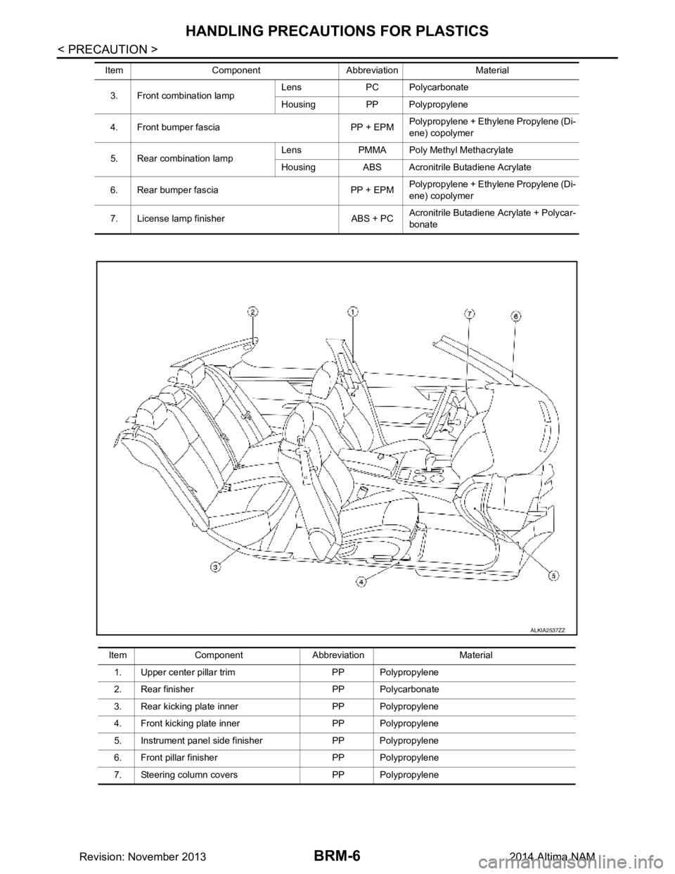
3. Front combination lampLens PC Polycarbonate
Housing PP Polypropylene
4. Front bumper fascia PP + EPM Polypropylene + Ethylene Propylene (Di-
ene) copolymer
5. Rear combination lamp Lens PMMA Poly Methyl Methacrylate
Housing ABS Acronitrile Butadiene Acrylate
6. Rear bumper fascia PP + EPM Polypropylene + Ethylene Propylene (Di-
ene) copolymer
7. License lamp finisher ABS + PC Acronitrile Butadiene Acrylate + Polycar-
bonate
Item Component Abbreviation Material
Item Component Abbreviation Material
1. Upper center pillar trim PP Polypropylene
2. Rear finisher PP Polycarbonate
3. Rear kicking plate inner PP Polypropylene
4. Front kicking plate inner PP Polypropylene
5. Instrument panel side finisher PP Polypropylene
6. Front pillar finisher PP Polypropylene
7. Steering column covers PP Polypropylene
ALKIA2537ZZ
Revision: November 20132014 Altima NAM
Page 745 of 4801
DEF-20
< DTC/CIRCUIT DIAGNOSIS >
REAR WINDOW DEFOGGER SWITCH
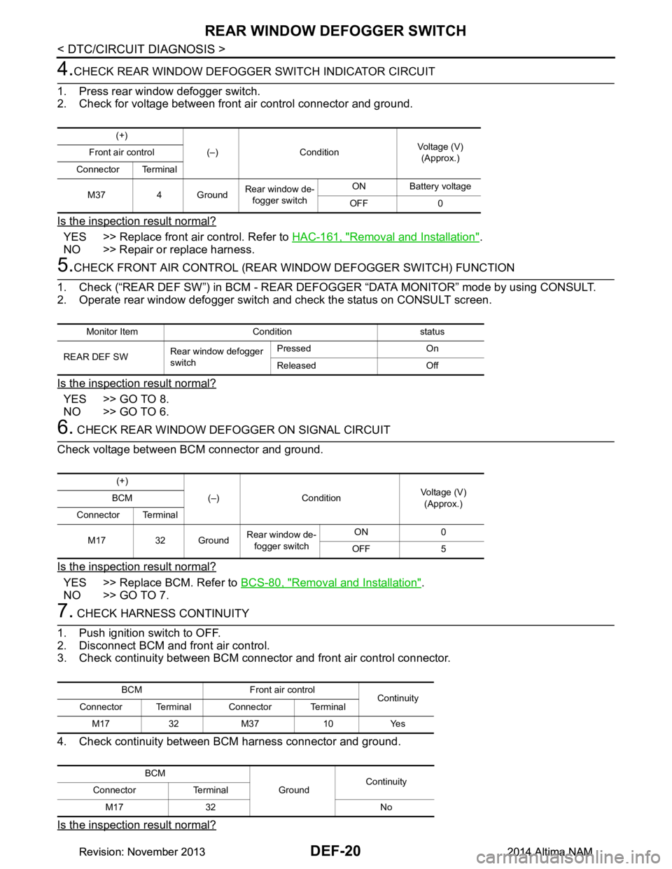
4.CHECK REAR WINDOW DEFOGGER SWITCH INDICATOR CIRCUIT
1. Press rear window defogger switch.
2. Check for voltage between front air control connector and ground.
Is the inspection result normal?
YES >> Replace front air control. Refer to HAC-161, "Removal and Installation".
NO >> Repair or replace harness.
5.CHECK FRONT AIR CONTROL (REAR WINDOW DEFOGGER SWITCH) FUNCTION
1. Check (“REAR DEF SW”) in BCM - REAR DEF OGGER “DATA MONITOR” mode by using CONSULT.
2. Operate rear window defogger switch and check the status on CONSULT screen.
Is the inspection result normal?
YES >> GO TO 8.
NO >> GO TO 6.
6. CHECK REAR WINDOW DEFO GGER ON SIGNAL CIRCUIT
Check voltage between BCM connector and ground.
Is the inspection result normal?
YES >> Replace BCM. Refer to BCS-80, "Removal and Installation".
NO >> GO TO 7.
7. CHECK HARNESS CONTINUITY
1. Push ignition switch to OFF.
2. Disconnect BCM and front air control.
3. Check continuity between BCM connec tor and front air control connector.
4. Check continuity between BCM harness connector and ground.
Is the inspection result normal?
(+) (–) Condition Voltage (V)
(Approx.)
Front air control
Connector Terminal
M37 4 Ground Rear window de-
fogger switch ON Battery voltage
OFF 0
Monitor Item Condition status
REAR DEF SW Rear window defogger
switch Pressed On
Released Off
(+) (–) Condition Voltage (V)
(Approx.)
BCM
Connector Terminal
M17 32 Ground Rear window de-
fogger switch ON 0
OFF 5
BCM Front air control Continuity
Connector Terminal Connector Terminal
M17 32 M37 10 Yes
BCM GroundContinuity
Connector Terminal
M17 32 No
Revision: November 20132014 Altima NAMRevision: November 20132014 Altima NAM
Page 746 of 4801
REAR WINDOW DEFOGGER SWITCHDEF-21
< DTC/CIRCUIT DIAGNOSIS >
C
D E
F
G H
I
J
K
M A
B
DEF
N
O P
YES >> Replace front air control. Refer to HAC-161, "Removal and Installation".
NO >> Repair or replace harness.
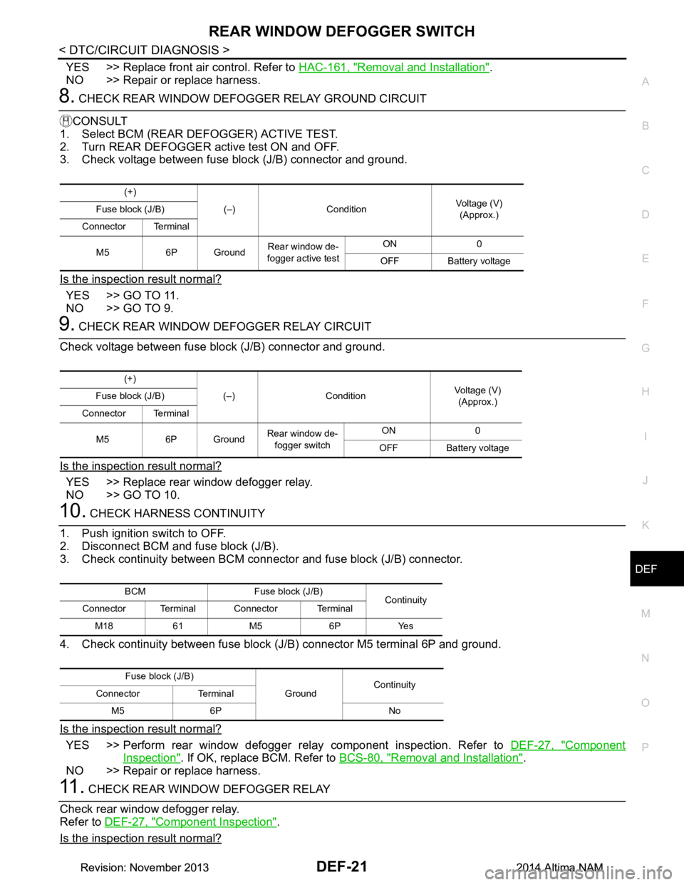
8. CHECK REAR WINDOW DEFOGGER RELAY GROUND CIRCUIT
CONSULT
1. Select BCM (REAR DEFOGGER) ACTIVE TEST.
2. Turn REAR DEFOGGER active test ON and OFF.
3. Check voltage between fuse block (J/B) connector and ground.
Is the inspection result normal?
YES >> GO TO 11.
NO >> GO TO 9.
9. CHECK REAR WINDOW DEFOGGER RELAY CIRCUIT
Check voltage between fuse block (J/B) connector and ground.
Is the inspection result normal?
YES >> Replace rear window defogger relay.
NO >> GO TO 10.
10. CHECK HARNESS CONTINUITY
1. Push ignition switch to OFF.
2. Disconnect BCM and fuse block (J/B).
3. Check continuity between BCM connector and fuse block (J/B) connector.
4. Check continuity between fuse block (J/B) connector M5 terminal 6P and ground.
Is the inspection result normal?
YES >> Perform rear window defogger relay component inspection. Refer to DEF-27, "Component
Inspection". If OK, replace BCM. Refer to BCS-80, "Removal and Installation".
NO >> Repair or replace harness.
11 . CHECK REAR WINDOW DEFOGGER RELAY
Check rear window defogger relay.
Refer to DEF-27, "Component Inspection"
.
Is the inspection result normal?
(+)
(–) Condition Voltage (V)
(Approx.)
Fuse block (J/B)
Connector Terminal
M5 6P Ground Rear window de-
fogger active test ON 0
OFF Battery voltage
(+) (–) Condition Voltage (V)
(Approx.)
Fuse block (J/B)
Connector Terminal
M5 6P Ground Rear window de-
fogger switch ON 0
OFF Battery voltage
BCM Fuse block (J/B) Continuity
Connector Terminal Connector Terminal
M18 61 M5 6P Yes
Fuse block (J/B) GroundContinuity
Connector Terminal
M5 6P No
Revision: November 20132014 Altima NAMRevision: November 20132014 Altima NAM
Page 748 of 4801
REAR WINDOW DEFOGGER SWITCHDEF-23
< DTC/CIRCUIT DIAGNOSIS >
C
D E
F
G H
I
J
K
M A
B
DEF
N
O P
Is the inspection result normal?
YES >> GO TO 4.
NO >> Perform rear window defogger relay diagnosis. Refer to DEF-26, "Diagnosis Procedure"
.
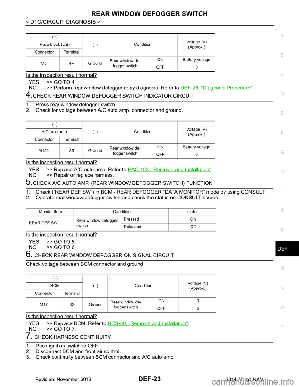
4.CHECK REAR WINDOW DEFOGGER SWITCH INDICATOR CIRCUIT
1. Press rear window defogger switch.
2. Check for voltage between A/C auto amp. connector and ground.
Is the inspection result normal?
YES >> Replace A/C auto amp. Refer to HAC-102, "Removal and Installation".
NO >> Repair or replace harness.
5.CHECK A/C AUTO AMP. (REAR WI NDOW DEFOGGER SWITCH) FUNCTION
1. Check (“REAR DEF SW”) in BCM - REAR DEFOGG ER “DATA MONITOR” mode by using CONSULT.
2. Operate rear window defogger switch and check the status on CONSULT screen.
Is the inspection result normal?
YES >> GO TO 8.
NO >> GO TO 6.
6. CHECK REAR WINDOW DEFOGGER ON SIGNAL CIRCUIT
Check voltage between BCM connector and ground.
Is the inspection result normal?
YES >> Replace BCM. Refer to BCS-80, "Removal and Installation".
NO >> GO TO 7.
7. CHECK HARNESS CONTINUITY
1. Push ignition switch to OFF.
2. Disconnect BCM and front air control.
3. Check continuity between BCM connector and A/C auto amp.
(+)
(–) Condition Voltage (V)
(Approx.)
Fuse block (J/B)
Connector Terminal
M5 4P Ground Rear window de-
fogger switch ON Battery voltage
OFF 0
(+) (–) Condition Voltage (V)
(Approx.)
A/C auto amp.
Connector Terminal
M152 35 Ground Rear window de-
fogger switch ON Battery voltage
OFF 0
Monitor Item Condition status
REAR DEF SW Rear window defogger
switch Pressed On
Released Off
(+) (–) Condition Voltage (V)
(Approx.)
BCM
Connector Terminal
M17 32 Ground Rear window de-
fogger switch ON 0
OFF 5
Revision: November 20132014 Altima NAMRevision: November 20132014 Altima NAM
Page 749 of 4801
DEF-24
< DTC/CIRCUIT DIAGNOSIS >
REAR WINDOW DEFOGGER SWITCH
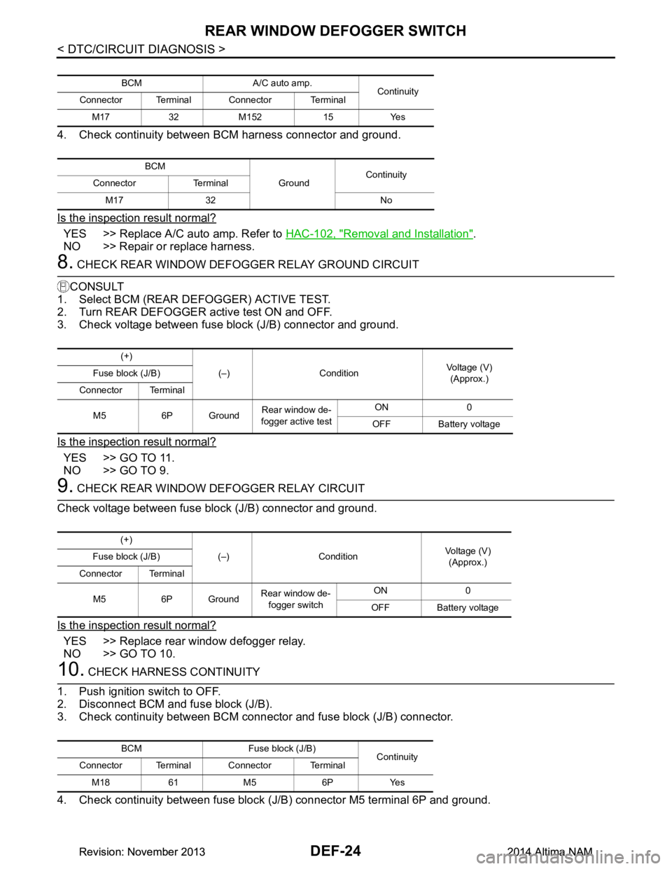
4. Check continuity between BCM harness connector and ground.
Is the inspection result normal?
YES >> Replace A/C auto amp. Refer to HAC-102, "Removal and Installation".
NO >> Repair or replace harness.
8. CHECK REAR WINDOW DEFOGGER RELAY GROUND CIRCUIT
CONSULT
1. Select BCM (REAR DE FOGGER) ACTIVE TEST.
2. Turn REAR DEFOGGER active test ON and OFF.
3. Check voltage between fuse block (J/B) connector and ground.
Is the inspection result normal?
YES >> GO TO 11.
NO >> GO TO 9.
9. CHECK REAR WINDOW DEFOGGER RELAY CIRCUIT
Check voltage between fuse block (J/B) connector and ground.
Is the inspection result normal?
YES >> Replace rear window defogger relay.
NO >> GO TO 10.
10. CHECK HARNESS CONTINUITY
1. Push ignition switch to OFF.
2. Disconnect BCM and fuse block (J/B).
3. Check continuity between BCM connec tor and fuse block (J/B) connector.
4. Check continuity between fuse block (J/B) connector M5 terminal 6P and ground.
BCM A/C auto amp. Continuity
Connector Terminal Connector Terminal
M17 32 M152 15 Yes
BCM GroundContinuity
Connector Terminal
M17 32 No
(+) (–) Condition Voltage (V)
(Approx.)
Fuse block (J/B)
Connector Terminal
M5 6P Ground Rear window de-
fogger active test ON 0
OFF Battery voltage
(+) (–) Condition Voltage (V)
(Approx.)
Fuse block (J/B)
Connector Terminal
M5 6P Ground Rear window de-
fogger switch ON 0
OFF Battery voltage
BCM Fuse block (J/B) Continuity
Connector Terminal Connector Terminal
M18 61 M5 6P Yes
Revision: November 20132014 Altima NAMRevision: November 20132014 Altima NAM
Page 792 of 4801
DLK-24
< SYSTEM DESCRIPTION >
SYSTEM (INTELLIGENT KEY SYSTEM)
DOOR LOCK FUNCTION
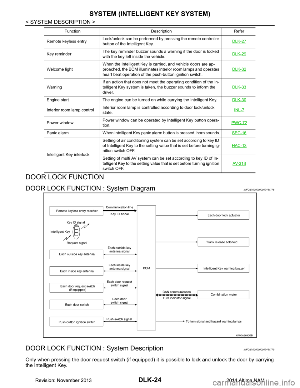
DOOR LOCK FUNCTION : System DiagramINFOID:0000000009461778
DOOR LOCK FUNCTION : System DescriptionINFOID:0000000009461779
Only when pressing the door request switch (if equipped) it is possible to lock and unlock the door by carrying
the Intelligent Key.
Remote keyless entry Lock/unlock can be performed by pressing the remote controller
button of the Intelligent Key. DLK-27
Key reminderThe key reminder buzzer sounds a warning if the door is locked
with the key left inside the vehicle. DLK-29
Welcome lightWhen the Intelligent Key is carried, and vehicle doors are ap-
proached, the BCM illuminates interior room lamps and operates
heart beat operation of the push-button ignition switch. DLK-32
WarningIf an action that does not meet the operating condition of the In-
telligent Key system is taken, the buzzer sounds to inform the
driver. DLK-33
Engine start The engine can be turned on while carrying the Intelligent Key.
DLK-30
Interior room lamp controlInterior room lamp is controlled according to door lock/unlock
state. INL-7
Power windowPower window can be operated by Intelligent Key button opera-
tion. PWC-72
Panic alarm When Intelligent Key panic alarm button is pressed, horn sounds.
SEC-16
Intelligent Key interlockSetting of air conditioning system can be set according to key ID
of Intelligent Key to the setting value that is set before turning ig-
nition switch OFF. HAC-13Setting of multi AV system can be set according to key ID of In-
telligent Key to the setting value that is set before turning ignition
switch OFF. AV- 3 1 8
Function Description Refer
AWKIA2690GB
Revision: November 20132014 Altima NAMRevision: November 20132014 Altima NAM
Page 1504 of 4801
![NISSAN TEANA 2014 Service Manual
EC-504
< DTC/CIRCUIT DIAGNOSIS >[QR25DE]
ELECTRICAL LOAD SIGNAL
>> INSPECTION END
3.CHECK HEADLAMP SYSTEM
Check headlamp system. Refer to EXL-86, "Work Flow"
.
>> INSPECTION END
4.CHECK HEATER FAN C](/img/5/57390/w960_57390-1503.png "NISSAN TEANA 2014 Service Manual
EC-504
< DTC/CIRCUIT DIAGNOSIS >[QR25DE]
ELECTRICAL LOAD SIGNAL
>> INSPECTION END
3.CHECK HEADLAMP SYSTEM
Check headlamp system. Refer to EXL-86, \"Work Flow\"
.
>> INSPECTION END
4.CHECK HEATER FAN C")
EC-504
< DTC/CIRCUIT DIAGNOSIS >[QR25DE]
ELECTRICAL LOAD SIGNAL
>> INSPECTION END
3.CHECK HEADLAMP SYSTEM
Check headlamp system. Refer to EXL-86, "Work Flow"
.
>> INSPECTION END
4.CHECK HEATER FAN CONTROL SYSTEM
Check heater fan control system. Refer to HAC-46, "Work Flow"
(with automatic air conditioner) or HAC-139,
"Work Flow" (with manual air conditioner).
>> INSPECTION END
Revision: November 20132014 Altima NAMRevision: November 20132014 Altima NAM
Page 1524 of 4801
![NISSAN TEANA 2014 Service Manual
EC-524
< DTC/CIRCUIT DIAGNOSIS >[QR25DE]
REFRIGERANT PRESSURE SENSOR
3.CHECK REFRIGERANT PRESSURE SENSOR GROUND CIRCUIT
1. Turn ignition switch OFF.
2. Disconnect ECM harness connector.
3. Check th](/img/5/57390/w960_57390-1523.png "NISSAN TEANA 2014 Service Manual
EC-524
< DTC/CIRCUIT DIAGNOSIS >[QR25DE]
REFRIGERANT PRESSURE SENSOR
3.CHECK REFRIGERANT PRESSURE SENSOR GROUND CIRCUIT
1. Turn ignition switch OFF.
2. Disconnect ECM harness connector.
3. Check th")
EC-524
< DTC/CIRCUIT DIAGNOSIS >[QR25DE]
REFRIGERANT PRESSURE SENSOR
3.CHECK REFRIGERANT PRESSURE SENSOR GROUND CIRCUIT
1. Turn ignition switch OFF.
2. Disconnect ECM harness connector.
3. Check the continuity between refrigerant pre ssure sensor harness connector and ECM harness connec-
tor.
*1: Except for California
*2: For California
4. Also check harness for short to power.
Is the inspection result normal?
YES >> GO TO 4.
NO >> Repair or replace error-detected parts.
4.CHECK REFRIGERANT PRESSURE SE NSOR INPUT SIGNAL CIRCUIT
1. Check the continuity between refrigerant pre ssure sensor harness connector and ECM harness connec-
tor.
*1: Except for California
*2: For California
2. Also check harness for short to ground and to power.
Is the inspection result normal?
YES >> GO TO 5.
NO >> Repair or replace error-detected parts.
5.CHECK INTERMITTENT INCIDENT
Check intermittent incident. Refer to GI-43, "Intermittent Incident"
.
Is the inspection result normal?
YES >> Replace refrigerant pressure sensor. Refer to HAC-107, "Removal and Installation" (with auto-
matic air conditioner) or HAC-163, "Removal and Installation"
(with manual air conditioner).
NO >> Repair or replace error-detected parts.
+-
Continuity
Refrigerant pressure sensor ECM
Connector Terminal Connector Terminal
E219 3 E10
*1
E31*2124 Existed
+-
Continuity
Refrigerant pressure sensor ECM
Connector Terminal Connector Terminal
E219 2 E10
*1
E31*2103 Existed
Revision: November 20132014 Altima NAMRevision: November 20132014 Altima NAM