Heater & air conditioning control system NISSAN TEANA 2014 Service Manual
[x] Cancel search | Manufacturer: NISSAN, Model Year: 2014, Model line: TEANA, Model: NISSAN TEANA 2014Pages: 4801, PDF Size: 51.2 MB
Page 1 of 4801
A
B
C
D
E
F
G
H
I
J
K
L
M
N
P
O
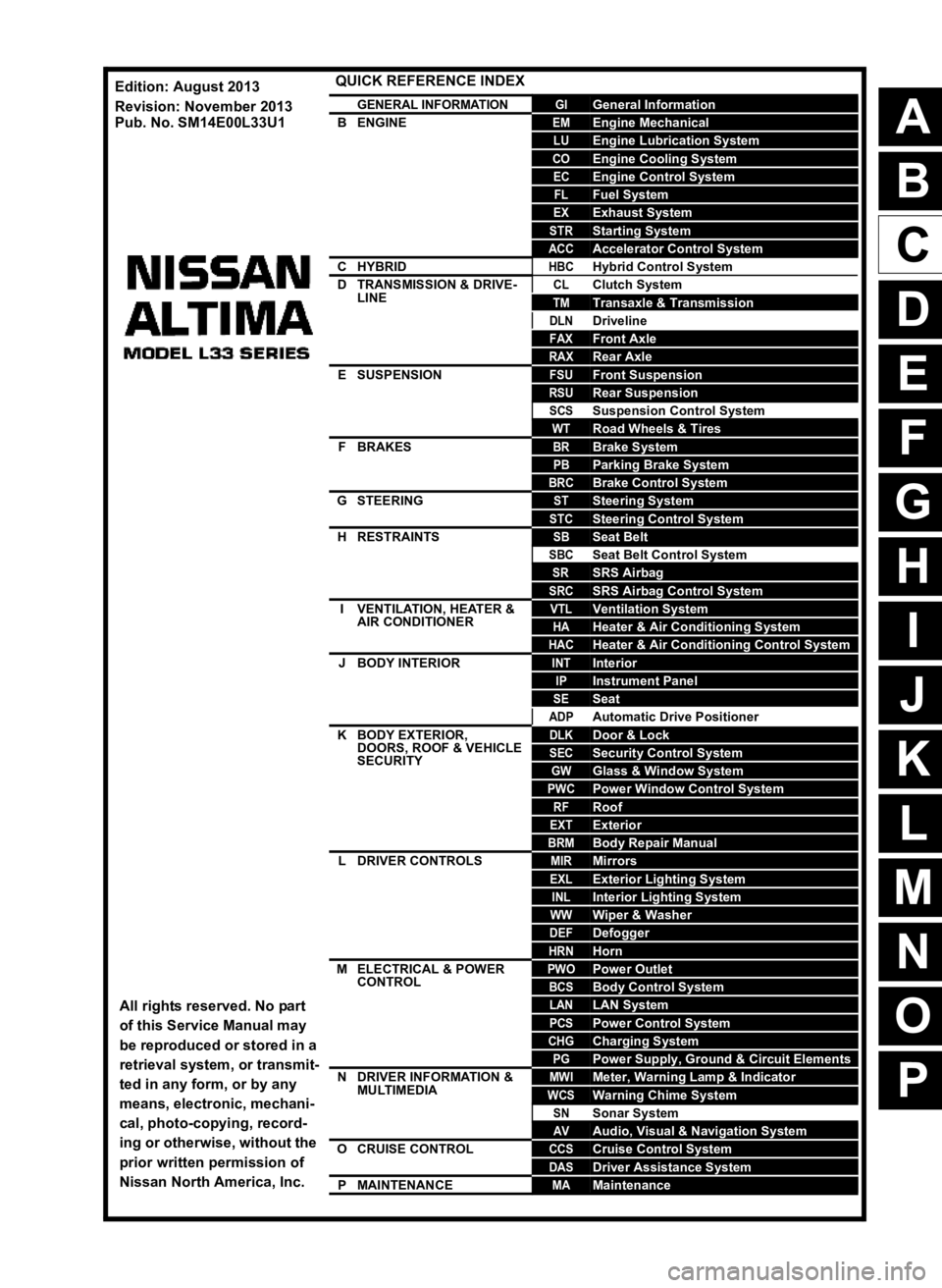
QUICK REFERENCE INDEX
AGENERAL INFORMATIONGIGeneral Information
BENGINEEMEngine Mechanical
LUEngine Lubrication System
COEngine Cooling System
ECEngine Control System
FLFuel System
EXExhaust System
STRStarting System
ACCAccelerator Control System
CHYBRIDHBCHybrid Control System
DTRANSMISSION & DRIVE-LINECLClutch System
TMTransaxle & Transmission
DLNDriveline
FAXFront Axle
RAXRear Axle
ESUSPENSIONFSUFront Suspension
RSURear Suspension
SCSSuspension Control System
WTRoad Wheels & Tires
FBRAKESBRBrake System
PBParking Brake System
BRCBrake Control System
GSTEERINGSTSteering System
STCSteering Control System
HRESTRAINTSSBSeat Belt
SBCSeat Belt Control System
SRSRS Airbag
SRCSRS Airbag Control System
IVENTILATION, HEATER &
AIR CONDITIONERVTLVentilation System
HAHeater & Air Conditioning System
HACHeater & Air Conditioning Control System
JBODY INTERIORINTInterior
IPInstrument Panel
SESeat
ADPAutomatic Drive Positioner
KBODY EXTERIOR, DOORS, ROOF & VEHICLE
SECURITYDLKDoor & Lock
SECSecurity Control System
GWGlass & Window System
PWCPower Window Control System
RFRoof
EXTExterior
BRMBody Repair Manual
LDRIVER CONTROLSMIRMirrors
EXLExterior Lighting System
INLInterior Lighting System
WWWiper & Washer
DEFDefogger
HRNHorn
MELECTRICAL & POWER
CONTROLPWOPower Outlet
BCSBody Control System
LANLAN System
PCSPower Control System
CHGCharging System
PGPower Supply, Ground & Circuit Elements
NDRIVER INFORMATION &
MULTIMEDIAMWIMeter, Warning Lamp & Indicator
WCSWarning Chime System
SNSonar System
AVAudio, Visual & Navigation System
OCRUISE CONTROLCCSCruise Control System
DASDriver Assistance System
PMAINTENANCEMAMaintenance
All rights reserved. No part
of this Service Manual may
be reproduced or stored in a
retrieval system, or transmit-
ted in any form, or by any
means, electronic, mechani-
cal, photo-copying, record-
ing or otherwise, without the
prior written permission of
Nissan North America, Inc.
Edition: August 2013
Revision: November 2013
Pub. No. SM14E00L33U1
Page 2623 of 4801
HEATER AND AIR CONDITIONING SYSTEM SYMPTOMS
HA-17
< SYMPTOM DIAGNOSIS >
C
D E
F
G H
J
K L
M A
B
HA
N
O P
SYMPTOM DIAGNOSIS
HEATER AND AIR CONDITIONING SYSTEM SYMPTOMS
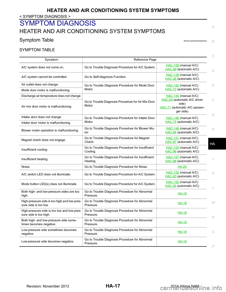
Symptom TableINFOID:0000000009463922
SYMPTOM TABLE
Symptom Reference Page
A/C system does not come on. Go to Trouble Diagnosis Procedure for A/C System. HAC-159
(manual A/C)
HAC-99
(automatic A/C)
A/C system cannot be controlled. Go to Self-diagnosis Function. HAC-139
(manual A/C)
HAC-46
(automatic A/C)
Air outlet does not change. Go to Trouble Diagnosis Procedure for Mode Door
Motor. HAC-142
(manual A/C)
HAC-73
(automatic A/C)
Mode door motor is malfunctioning.
Discharge air temperature does not change.
Go to Trouble Diagnosis Procedure for Air Mix Door
Motor. HAC-144
(manual A/C)
HAC-69
(automatic A/C driver side)
HAC-71
(automatic A/C passen-
ger side)
Air mix door motor is malfunctioning.
Intake door does not change.
Go to Trouble Diagnosis Procedure for Intake Door
Motor. HAC-146
(manual A/C)
HAC-75
(automatic A/C)
Intake door motor is malfunctioning.
Blower motor operation is malfunctioning. Go to Trouble Diagnosis Procedure for Blower Mo-
tor. HAC-148
(manual A/C)
HAC-84
(automatic A/C)
Magnet clutch does not engage. Go to Trouble Diagnosis Procedure for Magnet
Clutch. HAC-151
(manual A/C)
HAC-87
(automatic A/C)
Insufficient cooling. Go to Trouble Diagnosis Procedure for Insufficient
Cooling. HAC-155
(manual A/C)
HAC-96
(automatic A/C)
Insufficient heating. Go to Trouble Diagnosis Procedure for Insufficient
Heating. HAC-157
(manual A/C)
HAC-98
(automatic A/C)
Noise. Go to Trouble Diagnosis Procedure for Noise. HA-20
A/C switch LED does not illuminate. Go to Trouble Diagnosis Procedure for A/C System.HAC-152 (manual A/C)
HAC-83
(automatic A/C)
Mode button LED(s) does not illuminate. Go to Trouble Diagnosis Procedure for A/C System. HAC-152
(manual A/C)
HAC-83
(automatic A/C)
Both high- and low-pressure sides are too
high. Go to Trouble Diagnosis Procedure for Abnormal
Pressure. HA-18
High-pressure side is too high and low-pres-
sure side is too low. Go to Trouble Diagnosis Procedure for Abnormal
Pressure. HA-18
High-pressure side is too low and low-pres-
sure side is too high. Go to Trouble Diagnosis Procedure for Abnormal
Pressure. HA-18
Both high- and low-pressure side some-
times becomes negative. Go to Trouble Diagnosis Procedure for Abnormal
Pressure. HA-18
Low-pressure side sometimes becomes
negative. Go to Trouble Diagnosis Procedure for Abnormal
Pressure. HA-18
Low-pressure side becomes negative.
Go to Trouble Diagnosis Procedure for Abnormal
Pressure. HA-18
Revision: November 20132014 Altima NAM
Page 2650 of 4801
HAC-1
VENTILATION, HEATER & AIR CONDITIONER
C
D E
F
G H
J
K L
M
SECTION HAC
A
B
HAC
N
O P
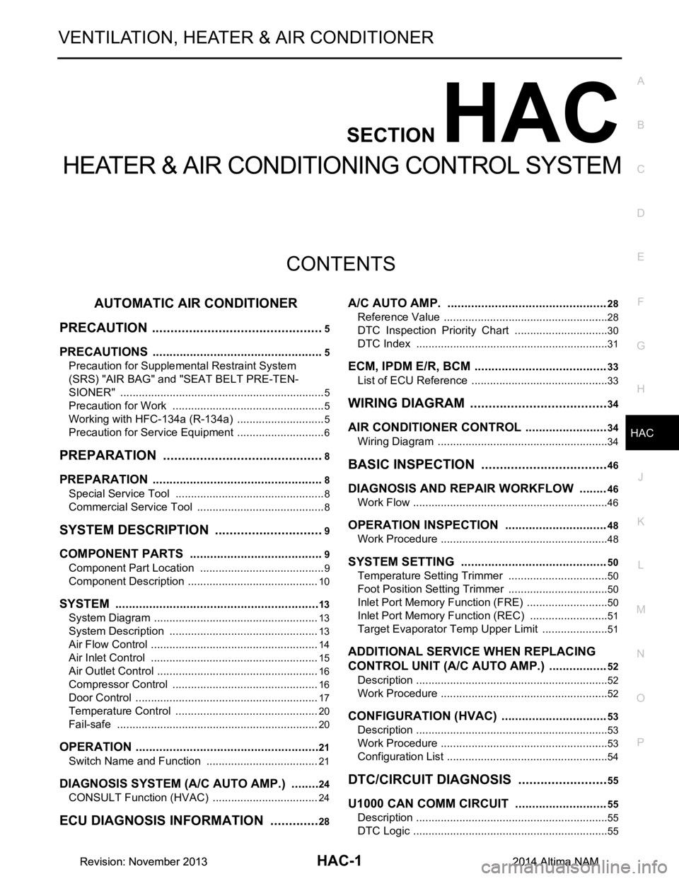
CONTENTS
HEATER & AIR CONDITIONING CONTROL SYSTEM
AUTOMATIC AIR CONDITIONER
PRECAUTION ................ ...............................
5
PRECAUTIONS .............................................. .....5
Precaution for Supplemental Restraint System
(SRS) "AIR BAG" and "SEAT BELT PRE-TEN-
SIONER" ............................................................. ......
5
Precaution for Work ..................................................5
Working with HFC-134a (R-134a) .............................5
Precaution for Service Equipment .............................6
PREPARATION ............................................8
PREPARATION .............................................. .....8
Special Service Tool ........................................... ......8
Commercial Service Tool ..........................................8
SYSTEM DESCRIPTION ..............................9
COMPONENT PARTS ................................... .....9
Component Part Location ................................... ......9
Component Description ...........................................10
SYSTEM .............................................................13
System Diagram .................................................. ....13
System Description .................................................13
Air Flow Control .......................................................14
Air Inlet Control .......................................................15
Air Outlet Control .....................................................16
Compressor Control ................................................16
Door Control ............................................................17
Temperature Control ...............................................20
Fail-safe ..................................................................20
OPERATION .......................................................21
Switch Name and Function ................................. ....21
DIAGNOSIS SYSTEM (A/C AUTO AMP.) .........24
CONSULT Function (HVAC) ............................... ....24
ECU DIAGNOSIS INFORMATION ..............28
A/C AUTO AMP. ...............................................28
Reference Value .................................................. ....28
DTC Inspection Priority Chart ...............................30
DTC Index ...............................................................31
ECM, IPDM E/R, BCM .......................................33
List of ECU Reference .............................................33
WIRING DIAGRAM ......................................34
AIR CONDITIONER CONTROL ........................34
Wiring Diagram .................................................... ....34
BASIC INSPECTION ...................................46
DIAGNOSIS AND REPAIR WORKFLOW ........46
Work Flow ............................................................ ....46
OPERATION INSPECTION ..............................48
Work Procedure .......................................................48
SYSTEM SETTING ...........................................50
Temperature Setting Trimmer ............................. ....50
Foot Position Setting Trimmer .................................50
Inlet Port Memory Function (FRE) ...........................50
Inlet Port Memory Function (REC) ..........................51
Target Evaporator Temp Upper Limit ......................51
ADDITIONAL SERVICE WHEN REPLACING
CONTROL UNIT (A/C AUTO AMP.) .................
52
Description ........................................................... ....52
Work Procedure .......................................................52
CONFIGURATION (HVAC) ...............................53
Description ...............................................................53
Work Procedure .......................................................53
Configuration List .....................................................54
DTC/CIRCUIT DIAGNOSIS .........................55
U1000 CAN COMM CIRCUIT ...........................55
Description ........................................................... ....55
DTC Logic ................................................................55
Revision: November 20132014 Altima NAMRevision: November 20132014 Altima NAM
Page 2651 of 4801
HAC-2
Diagnosis Procedure ..............................................55
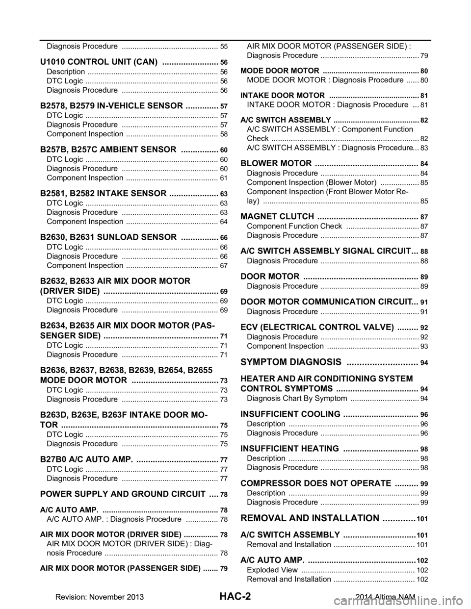
U1010 CONTROL UNIT (CAN) .........................56
Description ........................................................... ...56
DTC Logic ...............................................................56
Diagnosis Procedure ..............................................56
B2578, B2579 IN-VEHICLE SENSOR ...............57
DTC Logic ............................................................ ...57
Diagnosis Procedure ..............................................57
Component Inspection ............................................58
B257B, B257C AMBIENT SENSOR .................60
DTC Logic ............................................................ ...60
Diagnosis Procedure ..............................................60
Component Inspection ............................................61
B2581, B2582 INTAKE SENSOR ......................63
DTC Logic ............................................................ ...63
Diagnosis Procedure ..............................................63
Component Inspection ............................................64
B2630, B2631 SUNLOAD SENSOR .................66
DTC Logic ............................................................ ...66
Diagnosis Procedure ..............................................66
Component Inspection ............................................67
B2632, B2633 AIR MIX DOOR MOTOR
(DRIVER SIDE) ............................................... ...
69
DTC Logic ............................................................ ...69
Diagnosis Procedure ..............................................69
B2634, B2635 AIR MIX DOOR MOTOR (PAS-
SENGER SIDE) ............................................... ...
71
DTC Logic ............................................................ ...71
Diagnosis Procedure ..............................................71
B2636, B2637, B2638, B2639, B2654, B2655
MODE DOOR MOTOR ................................... ...
73
DTC Logic ............................................................ ...73
Diagnosis Procedure ..............................................73
B263D, B263E, B263F INTAKE DOOR MO-
TOR ................................................................. ...
75
DTC Logic ............................................................ ...75
Diagnosis Procedure ..............................................75
B27B0 A/C AUTO AMP. ....................................77
DTC Logic ............................................................ ...77
Diagnosis Procedure ..............................................77
POWER SUPPLY AND GROUND CIRCUIT .....78
A/C AUTO AMP. .................................................... ...78
A/C AUTO AMP. : Diagnosis Procedure ................78
AIR MIX DOOR MOTOR (DRIVER SIDE) .............. ...78
AIR MIX DOOR MOTOR (DRIVER SIDE) : Diag-
nosis Procedure ................................................... ...
78
AIR MIX DOOR MOTOR (PASSENGER SIDE) ..... ...79
AIR MIX DOOR MOTOR (PASSENGER SIDE) :
Diagnosis Procedure ............................................ ...
79
MODE DOOR MOTOR ........................................... ...80
MODE DOOR MOTOR : Diagnosis Procedure .......80
INTAKE DOOR MOTOR ........................................ ...81
INTAKE DOOR MOTOR : Diagnosis Procedure ....81
A/C SWITCH ASSEMBLY .........................................82
A/C SWITCH ASSEMBLY : Component Function
Check ................................................................... ...
82
A/C SWITCH ASSEMBLY : Diagnosis Procedure ...83
BLOWER MOTOR .......................................... ...84
Diagnosis Procedure ............................................ ...84
Component Inspection (Blower Motor) ...................85
Component Inspection (Front Blower Motor Re-
lay) ....................................................................... ...
85
MAGNET CLUTCH ............................................87
Component Function Check ................................ ...87
Diagnosis Procedure ...............................................87
A/C SWITCH ASSEMBLY SIGNAL CIRCUIT ...88
Diagnosis Procedure ...............................................88
DOOR MOTOR ..................................................89
Diagnosis Procedure ............................................ ...89
DOOR MOTOR COMMUNICATION CIRCUIT ...91
Diagnosis Procedure ............................................ ...91
ECV (ELECTRICAL CONTROL VALVE) ..........92
Diagnosis Procedure ............................................ ...92
Component Inspection ............................................93
SYMPTOM DIAGNOSIS ............................94
HEATER AND AIR CONDITIONING SYSTEM
CONTROL SYMPTOMS ................................. ...
94
Diagnosis Chart By Symptom .............................. ...94
INSUFFICIENT COOLING .................................96
Description ........................................................... ...96
Diagnosis Procedure ...............................................96
INSUFFICIENT HEATING .................................98
Description ........................................................... ...98
Diagnosis Procedure ...............................................98
COMPRESSOR DOES NOT OPERATE ...........99
Description ........................................................... ...99
Diagnosis Procedure ...............................................99
REMOVAL AND INSTALLATION .............101
A/C SWITCH ASSEMBLY .............................. ..101
Removal and Installation .......................................101
A/C AUTO AMP. ............................................. ..102
Exploded View ..................................................... .102
Removal and Installation .......................................102
Revision: November 20132014 Altima NAMRevision: November 20132014 Altima NAM
Page 2653 of 4801
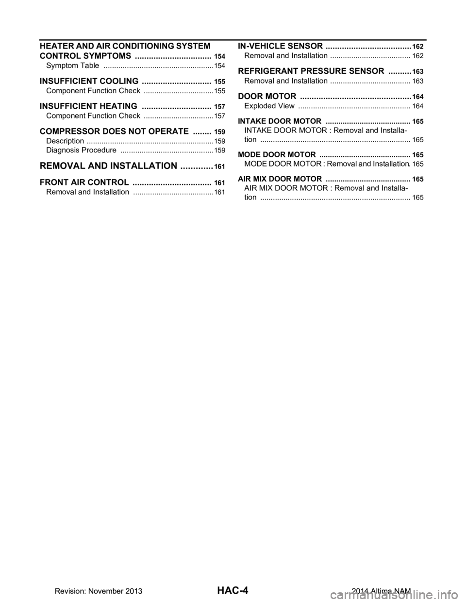
HAC-4
HEATER AND AIR CONDITIONING SYSTEM
CONTROL SYMPTOMS ................................. .
154
Symptom Table ................................................... ..154
INSUFFICIENT COOLING ...............................155
Component Function Check ................................ ..155
INSUFFICIENT HEATING ...............................157
Component Function Check ................................ ..157
COMPRESSOR DOES NOT OPERATE .........159
Description ........................................................... ..159
Diagnosis Procedure .............................................159
REMOVAL AND INSTALLATION ..............161
FRONT AIR CONTROL .................................. .161
Removal and Installation ..................................... ..161
IN-VEHICLE SENSOR ......................................162
Removal and Installation .......................................162
REFRIGERANT PRESSURE SENSOR ......... ..163
Removal and Installation .......................................163
DOOR MOTOR ............................................... ..164
Exploded View ..................................................... .164
INTAKE DOOR MOTOR ........................................ .165
INTAKE DOOR MOTOR : Removal and Installa-
tion ....................................................................... .
165
MODE DOOR MOTOR ........................................... .165
MODE DOOR MOTOR : Removal and Installation .165
AIR MIX DOOR MOTOR ........................................ .165
AIR MIX DOOR MOTOR : Removal and Installa-
tion ....................................................................... .
165
Revision: November 20132014 Altima NAMRevision: November 20132014 Altima NAM
Page 2743 of 4801

HAC-94
< SYMPTOM DIAGNOSIS >[AUTOMATIC AIR CONDITIONER]
HEATER AND AIR CONDITIONING
SYSTEM CONTROL SYMPTOMS
SYMPTOM DIAGNOSIS
HEATER AND AIR CONDITIONING SYSTEM CONTROL SYMPTOMS
Diagnosis Chart By SymptomINFOID:0000000009463166
NOTE:
Perform the self-diagnoses with CONSULT before perfo rming the symptom diagnosis. If DTC is detected, per-
form the corresponding diagnosis.
Symptom Corresponding malfunction part Reference
• Air conditioning does not activate.
• Air conditioning cannot be controlled.
• Operation status of air conditioning is not indicated on display. • A/C auto amp. ignition power supply
circuit
• Front A/C control (A/C auto amp.) HAC-78, "A/C AUTO AMP. : Diag-
nosis Procedure"
• Air outlet does not change.
• Mode door motor does not operate normally. • Circuit between mode door motor
and A/C auto amp.
• Mode door motor control linkage
• Mode door motor
• A/C auto amp. HAC-80, "MODE DOOR MOTOR :
Diagnosis Procedure"
• Discharge air temperature of driver side does not
change.
• Air mix door motor LH does not operate normally. • Circuit between air mix door motor
LH and A/C auto amp.
• Air mix door motor LH installation condition
• Air mix door motor LH
• A/C auto amp. HAC-78, "AIR MIX DOOR MOTOR
(DRIVER SIDE) : Diagnosis Proce-
dure"
• Discharge air temperature of passenger side does
not change.
• Air mix door motor RH does not operate normally. • Circuit between air mix door motor
RH and A/C auto amp.
• Air mix door motor RH installation condition
• Air mix door motor RH
• A/C auto amp. HAC-79, "AIR MIX DOOR MOTOR
(PASSENGER SIDE) : Diagnosis
Procedure"
• Intake door does not change.
• Intake door motor does not operate normally. • Circuit between intake door motor
and A/C auto amp.
• Intake door motor control linkage
• Intake door motor
• A/C auto amp. HAC-81, "INTAKE DOOR MOTOR :
Diagnosis Procedure"
All door motors do not operate normally.
• Each door motor power supply and
ground circuit
• A/C auto amp. HAC-89, "Diagnosis Procedure"
Blower motor operation is malfunctioning. • Power supply system of front blower
motor
• Circuit between front blower motor
and A/C auto amp.
• Front blower motor
• A/C auto amp. HAC-84, "Diagnosis Procedure"
Compressor does not operate. • Circuit between magnet clutch and
IPDM E/R
• Magnet clutch
• IPDM E/R (A/C relay)
• Circuit between ECM and refriger- ant pressure sensor
• Refrigerant pressure sensor
• CAN communication circuit
• A/C auto amp. HAC-87, "Diagnosis Procedure"
Revision: November 20132014 Altima NAMRevision: November 20132014 Altima NAM
Page 2744 of 4801

HEATER AND AIR CONDITIONING SYSTEM CONTROL SYMPTOMS
HAC-95
< SYMPTOM DIAGNOSIS > [AUTOMATIC AIR CONDITIONER]
C
D E
F
G H
J
K L
M A
B
HAC
N
O P
• Insufficient cooling.
• No cool air comes out. (Air flow volume is normal.) • Magnet clutch control system
• Drive belt slipping
• Refrigerant cycle
• ECV (electrical control valve)
• Air leakage from each duct
• A/C auto amp. connection recogni- tion signal circuit
• Temperature setting trimmer (front)HAC-96, "Diagnosis Procedure"
• Insufficient heating.
• No warm air comes out. (Air flow volume is nor- mal.) • Engine cooling system
• Heater hose
• Heater core
• Air leakage from each duct
• Temperature setting trimmer (front)HAC-98, "Diagnosis Procedure"
Noise is heard when front
air conditioning system op-
erates. During compressor
operation Refrigerant cycle
HA-18, "Symptom Table"
During front blower
motor operation • Mixing any foreign object in front
blower motor
• Front blower motor fan breakage
• Front blower motor rotation inferiori-
ty HAC-85, "Component Inspection
(Blower Motor)"
• Memory function does not operate.
• Setting temperature is not memorized. • Battery power supply system of A/C
auto amp.
• A/C auto amp. HAC-78, "A/C AUTO AMP. : Diag-
nosis Procedure"
Symptom Corresponding malfunction part Reference
Revision: November 20132014 Altima NAMRevision: November 20132014 Altima NAM
Page 2747 of 4801

HAC-98
< SYMPTOM DIAGNOSIS >[AUTOMATIC AIR CONDITIONER]
INSUFFICIENT HEATING
INSUFFICIENT HEATING
DescriptionINFOID:0000000009463169
Symptom
• Insufficient heating
• No warm air comes out. (Air flow volume is normal.)
Diagnosis ProcedureINFOID:0000000009463170
NOTE:
Perform self-diagnosis with CONSULT before performing symptom diagnosis. If DTC is detected, perform the
corresponding diagnosis.
1.CHECK COOLING SYSTEM
1. Check engine coolant level and check leakage. Refer to CO-11, "System Inspection"
(QR25DE) or CO-
35, "System Inspection" (VQ35DE).
2. Check reservoir tank cap. Refer to CO-11, "System Inspection"
(QR25DE) or CO-35, "System Inspection"
(VQ35DE).
3. Check water flow sounds of the engine coolant. Refer to CO-11, "System Inspection"
(QR25DE) or CO-
35, "System Inspection" (VQ35DE).
Is the inspection result normal?
YES >> GO TO 2.
NO >> Refill engine coolant and repair or repl ace parts depending on the inspection results.
2.CHECK HEATER HOSE
Check installation of heater hose visually or by touching.
Is the inspection result normal?
YES >> GO TO 3.
NO >> Repair or replace parts depending on the inspection results.
3.CHECK HEATER CORE
1. Check temperature of inlet hose and outlet hose of front heater core.
2. Check that inlet side of heater core is hot and the outle t side is slightly lower than/almost equal to the inlet
side.
CAUTION:
Always perform the temperature in spection in a short period of time because the engine coolant
temperature is very hot.
Is the inspection result normal?
YES >> GO TO 4.
NO >> Replace heater core. Refer to HA-42, "HEATER CORE : Removal and Installation"
.
4.CHECK AIR LEAKAGE FROM EACH DUCT
Check duct and nozzle, etc. of front air conditioning system for air leakage.
Is the inspection result normal?
YES >> GO TO 5.
NO >> Repair or replace parts depending on the inspection results.
5.CHECK SETTING OF TEMPERATURE SETTING TRIMMER (FRONT)
1. Check setting value of temperature setting trimmer (front). Refer to HAC-50, "Temperature Setting Trim-
mer".
2. Check that temperature setting trimmer (front) is set to “ − direction”.
NOTE:
The control temperature can be set by t he temperature setting trimmer (front).
3. Set difference between the set temperature and control temperature to “0”.
Are the symptoms solved?
YES >> Inspection End.
NO >> Replace A/C auto amp. Refer to HAC-102, "Removal and Installation"
.
Revision: November 20132014 Altima NAMRevision: November 20132014 Altima NAM
Page 2803 of 4801

HAC-154
< SYMPTOM DIAGNOSIS >[MANUAL AIR CONDITIONER]
HEATER AND AIR CONDITIONING
SYSTEM CONTROL SYMPTOMS
SYMPTOM DIAGNOSIS
HEATER AND AIR CONDITIONING SYSTEM CONTROL SYMPTOMS
Symptom TableINFOID:0000000009463222
SYMPTOM TABLE
Symptom Reference Page
A/C system does not come on. Go to Trouble Diagnosis Procedure for A/C System. HAC-152, "Diagno-
sis Procedure"
Air outlet does not change.
Go to Trouble Diagnosis Procedure for Mode Door Motor. (LIN) HAC-142, "Diagno-
sis Procedure"Mode door motor does not operate normally.
Discharge air temperature does not change. Go to Trouble Diagnosis Procedure for Air Mix Door Motor. (LIN) HAC-144, "Diagno-
sis Procedure"Air mix door motor does not operate normal-
ly.
Intake door does not change. Go to Trouble Diagnosis Procedure for Intake Door Motor. (LIN) HAC-146, "Diagno-
sis Procedure"Intake door motor does not operate normally.
Blower motor operation is malfunctioning. Go to Trouble Diagnosis Procedure for Blower Motor. HAC-148, "Diagno-
sis Procedure"
Magnet clutch does not engage. Go to Trouble Diagnosis Procedure for Magnet Clutch.HAC-151, "Diagno-sis Procedure"
Insufficient cooling Go to Trouble Diagnosis Procedure for Insufficient Cooling.HAC-155, "Compo-nent Function
Check"
Insufficient heating Go to Trouble Diagnosis Procedure for Insufficient Heating.HAC-157, "Compo-nent Function
Check"
Noise Go to Trouble Diagnosis Procedure for Noise.
HA-20, "Symptom Table"
Revision: November 20132014 Altima NAMRevision: November 20132014 Altima NAM
Page 3439 of 4801
PG
INSPECTION AND ADJUSTMENTPG-7
< BASIC INSPECTION >
C
D E
F
G H
I
J
K L
B
A
O P
N
INSPECTION AND ADJUSTMENT
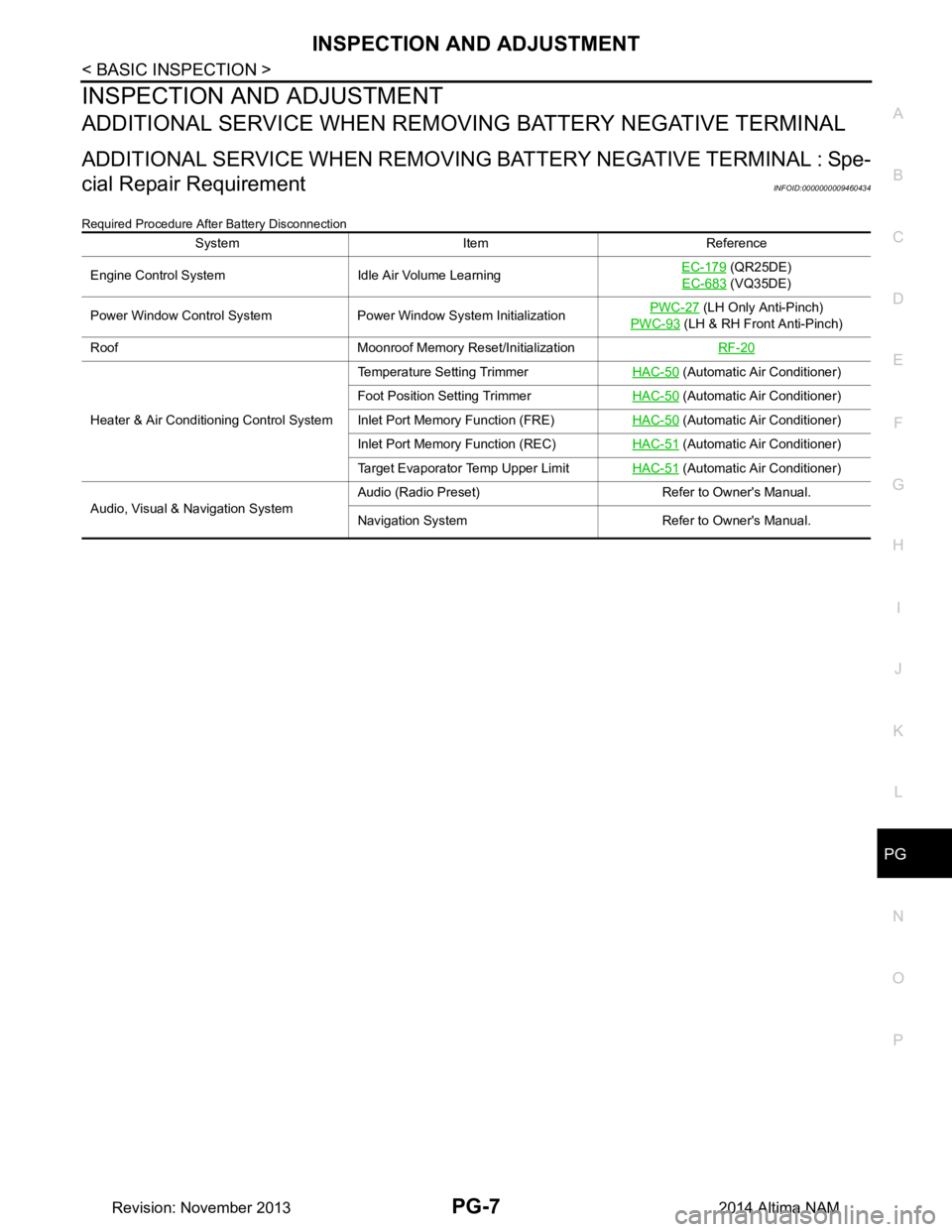
ADDITIONAL SERVICE WHEN REMOVI
NG BATTERY NEGATIVE TERMINAL
ADDITIONAL SERVICE WHEN REMOVING BATTERY NEGATIVE TERMINAL : Spe-
cial Repair Requirement
INFOID:0000000009460434
Required Procedure After Battery Disconnection
System Item Reference
Engine Control System Idle Air Volume Learning EC-179
(QR25DE)
EC-683
(VQ35DE)
Power Window Control System Power Window System Initialization PWC-27
(LH Only Anti-Pinch)
PWC-93
(LH & RH Front Anti-Pinch)
Roof Moonroof Memory Reset/Initialization RF-20
Heater & Air Conditioning Control SystemTemperature Setting Trimmer
HAC-50
(Automatic Air Conditioner)
Foot Position Setting Trimmer HAC-50
(Automatic Air Conditioner)
Inlet Port Memory Function (FRE) HAC-50
(Automatic Air Conditioner)
Inlet Port Memory Function (REC) HAC-51
(Automatic Air Conditioner)
Target Evaporator Temp Upper Limit HAC-51
(Automatic Air Conditioner)
Audio, Visual & Navigation System Audio (Radio Preset) Refer to Owner's Manual.
Navigation System Refer to Owner's Manual.
Revision: November 20132014 Altima NAM