brakes NISSAN TEANA 2014 Service Manual
[x] Cancel search | Manufacturer: NISSAN, Model Year: 2014, Model line: TEANA, Model: NISSAN TEANA 2014Pages: 4801, PDF Size: 51.2 MB
Page 1 of 4801

A
B
C
D
E
F
G
H
I
J
K
L
M
N
P
O
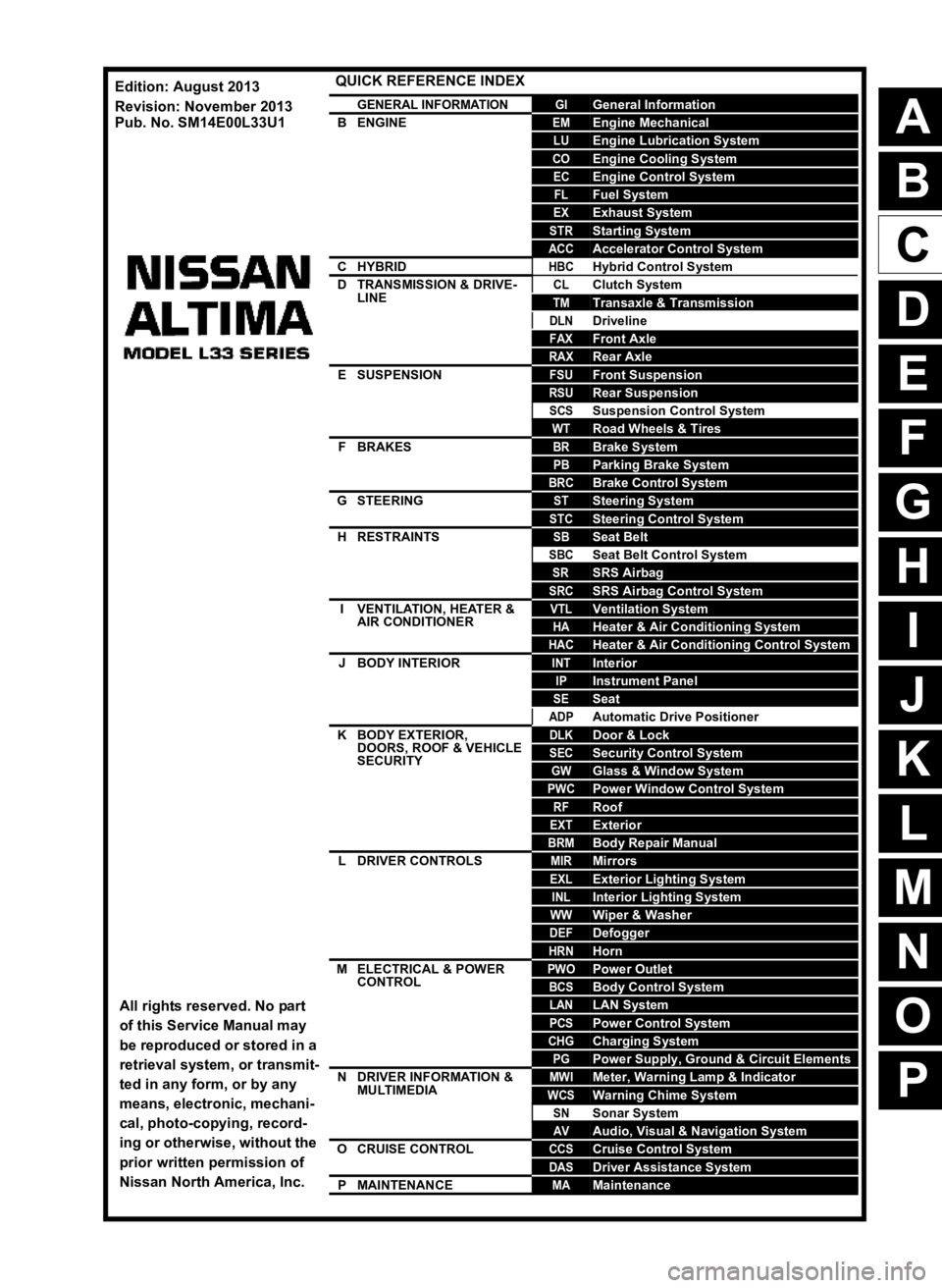
QUICK REFERENCE INDEX
AGENERAL INFORMATIONGIGeneral Information
BENGINEEMEngine Mechanical
LUEngine Lubrication System
COEngine Cooling System
ECEngine Control System
FLFuel System
EXExhaust System
STRStarting System
ACCAccelerator Control System
CHYBRIDHBCHybrid Control System
DTRANSMISSION & DRIVE-LINECLClutch System
TMTransaxle & Transmission
DLNDriveline
FAXFront Axle
RAXRear Axle
ESUSPENSIONFSUFront Suspension
RSURear Suspension
SCSSuspension Control System
WTRoad Wheels & Tires
FBRAKESBRBrake System
PBParking Brake System
BRCBrake Control System
GSTEERINGSTSteering System
STCSteering Control System
HRESTRAINTSSBSeat Belt
SBCSeat Belt Control System
SRSRS Airbag
SRCSRS Airbag Control System
IVENTILATION, HEATER &
AIR CONDITIONERVTLVentilation System
HAHeater & Air Conditioning System
HACHeater & Air Conditioning Control System
JBODY INTERIORINTInterior
IPInstrument Panel
SESeat
ADPAutomatic Drive Positioner
KBODY EXTERIOR, DOORS, ROOF & VEHICLE
SECURITYDLKDoor & Lock
SECSecurity Control System
GWGlass & Window System
PWCPower Window Control System
RFRoof
EXTExterior
BRMBody Repair Manual
LDRIVER CONTROLSMIRMirrors
EXLExterior Lighting System
INLInterior Lighting System
WWWiper & Washer
DEFDefogger
HRNHorn
MELECTRICAL & POWER
CONTROLPWOPower Outlet
BCSBody Control System
LANLAN System
PCSPower Control System
CHGCharging System
PGPower Supply, Ground & Circuit Elements
NDRIVER INFORMATION &
MULTIMEDIAMWIMeter, Warning Lamp & Indicator
WCSWarning Chime System
SNSonar System
AVAudio, Visual & Navigation System
OCRUISE CONTROLCCSCruise Control System
DASDriver Assistance System
PMAINTENANCEMAMaintenance
All rights reserved. No part
of this Service Manual may
be reproduced or stored in a
retrieval system, or transmit-
ted in any form, or by any
means, electronic, mechani-
cal, photo-copying, record-
ing or otherwise, without the
prior written permission of
Nissan North America, Inc.
Edition: August 2013
Revision: November 2013
Pub. No. SM14E00L33U1
Page 97 of 4801

BR-1
BRAKES
C
D E
G H
I
J
K L
M
SECTION BR
A
B
BR
N
O P
CONTENTS
BRAKE SYSTEM
PRECAUTION ................ ...............................3
PRECAUTIONS .............................................. .....3
Precaution for Supplemental Restraint System
(SRS) "AIR BAG" and "SEAT BELT PRE-TEN-
SIONER" ............................................................. ......
3
Precaution for Procedure without Cowl Top Cover ......3
Precaution for Brake System ....................................3
PREPARATION ............................................5
PREPARATION .............................................. .....5
Special Service Tool ........................................... ......5
Commercial Service Tool ..........................................5
SYSTEM DESCRIPTION ..............................6
NOISE, VIBRATION AND HARSHNESS
(NVH) TROUBLESHOOTING ........................ .....
6
NVH Troubleshooting Chart ................................ ......6
BASIC INSPECTION ....................................7
BRAKE PEDAL .............................................. .....7
Inspection ............................................................ ......7
BRAKE FLUID .....................................................8
Inspection ............................................................ ......8
BRAKE MASTER CYLINDER ........................ .....9
Inspection ............................................................ ......9
On Board Inspection .................................................9
BRAKE BOOSTER ............................................10
Inspection ............................................................ ....10
FRONT DISC BRAKE .................................... ....11
BRAKE PAD .......................................................... ....11
BRAKE PAD : Inspection ........................................11
DISC ROTOR ......................................................... ....11
DISC ROTOR : Inspection ......................................11
REAR DISC BRAKE .........................................12
BRAKE PAD .......................................................... ....12
BRAKE PAD : Inspection .........................................12
DISC ROTOR ......................................................... ....12
DISC ROTOR : Inspection .......................................12
PERIODIC MAINTENANCE ........................13
BRAKE PEDAL ................................ .................13
Inspection and Adjustment .................................. ....13
BRAKE FLUID ................................. .................14
Drain and Refill .................................................... ....14
Bleeding Brake System ...........................................14
FRONT DISC BRAKE .......................................16
Brake Burnishing ................................................. ....16
REAR DISC BRAKE .........................................17
Brake Burnishing ................................................. ....17
REMOVAL AND INSTALLATION ...............18
BRAKE PEDAL ................................ .................18
Exploded View ..................................................... ....18
Removal and Installation .........................................18
BRAKE PIPING ................................ .................20
FRONT ................................................................... ....20
FRONT : Exploded View .........................................20
FRONT : Hydraulic Piping .......................................21
FRONT : Removal and Installation ..........................21
REAR ..................................................................... ....23
REAR : Exploded View ............................................23
REAR : Hydraulic Piping ..........................................24
REAR : Removal and Installation ............................24
BRAKE MASTER CYLINDER ..........................26
Exploded View .........................................................26
Removal and Installation .........................................26
Revision: November 20132014 Altima NAM
Page 112 of 4801

BR-16
< PERIODIC MAINTENANCE >
FRONT DISC BRAKE
FRONT DISC BRAKE
Brake BurnishingINFOID:0000000009463694
CAUTION:
• Burnish contact surfaces between brake pads and disc brake rotor according to the following proce-
dure after refinishing the disc brake rotor, replacing brake pads or if a soft pedal occurs at very low
mileage.
• Be careful of vehicle speed. Brakes do not operat e firmly/securely until pads and disc rotor are
securely seated.
• Only perform this procedure under safe road and traffic conditions. Use extreme caution.
1. Drive the vehicle on straight, flat road.
2. Depress the brake pedal until the vehicle stops.
3. Release the brake pedal for a few minutes to allow the brake components to cool.
4. Repeat steps 1 to 3 until pad and disc rotor are securely seated.
Revision: November 20132014 Altima NAM
Page 147 of 4801

BRC-1
BRAKES
C
D E
G H
I
J
K L
M
SECTION BRC
A
B
BRC
N
O P
CONTENTS
BRAKE CONTROL SYSTEM
VDC/TCS/ABS
PRECAUTION ................ ...............................
4
PRECAUTIONS .............................................. .....4
Precaution for Supplemental Restraint System
(SRS) "AIR BAG" and "SEAT BELT PRE-TEN-
SIONER" ............................................................. ......
4
Precaution for Brake System ....................................4
Precaution for Brake Control .....................................5
Precaution for CAN System ................................ ......5
Precaution for Work ..................................................6
PREPARATION ............................................7
PREPARATION .............................................. .....7
Special Service Tool ........................................... ......7
Commercial Service Tool ..........................................7
SYSTEM DESCRIPTION ..............................8
COMPONENT PARTS ................................... .....8
Component Parts Location .................................. ......8
Component Description .............................................9
ABS Actuator and Electric Unit (Control Unit) ...........9
Wheel Sensor and Sensor Rotor ............................10
Stop Lamp Switch ...................................................10
Steering Angle Sensor ............................................10
Brake Fluid Level Switch .........................................10
Vacuum Sensor .......................................................10
Parking Brake Switch ..............................................11
VDC OFF Switch .....................................................11
SYSTEM .............................................................12
VDC/TCS/ABS ....................................................... ....12
VDC/TCS/ABS : System Diagram ...........................12
VDC/TCS/ABS : System De scription ......................12
VDC/TCS/ABS : VDC Functi on ...............................23
VDC/TCS/ABS : TCS Functi on ...............................25
VDC/TCS/ABS : ABS Function ........................... ....27
VDC/TCS/ABS : EBD Functi on ...............................28
VDC/TCS/ABS : Fail-safe ... .....................................29
DIAGNOSIS SYSTEM [ABS ACTUATOR
AND ELECTRIC UNIT (CONTROL UNIT)] .......
33
CONSULT Function (ABS) .................................. ....33
ECU DIAGNOSIS INFORMATION ..............38
ABS ACTUATOR AND ELECTRIC UNIT
(CONTROL UNIT) .............................................
38
Reference Value .................................................. ....38
Fail-safe ...................................................................41
DTC Inspection Priority Chart ..................................44
DTC Index ...............................................................45
WIRING DIAGRAM ......................................47
BRAKE CONTROL SYSTEM ...........................47
Wiring Diagram .................................................... ....47
BASIC INSPECTION ...................................55
DIAGNOSIS AND REPAIR WORK FLOW .......55
Work Flow ............................................................ ....55
Diagnostic Work Sheet ............................................56
ADDITIONAL SERVICE WHEN REPLACING
ABS ACTUATOR AND ELECTRIC UNIT
(CONTROL UNIT) .............................................
57
Description ........................................................... ....57
ADJUSTMENT OF STEERING ANGLE SEN-
SOR NEUTRAL POSITION ...............................
58
Description ........................................................... ....58
Work Procedure .......................................................58
CONFIGURATION [ABS ACTUATOR AND
ELECTRIC UNIT (CONTROL UNIT)] ................
60
Work Procedure ................................................... ....60
CALIBRATION OF DECEL G SENSOR ...........62
Description ...............................................................62
Revision: November 20132014 Altima NAMRevision: November 20132014 Altima NAM
Page 170 of 4801
![NISSAN TEANA 2014 Service Manual
BRC-24
< SYSTEM DESCRIPTION >[VDC/TCS/ABS]
SYSTEM
• Brake force control function
at braking hard detects driver′s brake operations with the pressure sensor,
judges a brake booster ′s maximum b NISSAN TEANA 2014 Service Manual
BRC-24
< SYSTEM DESCRIPTION >[VDC/TCS/ABS]
SYSTEM
• Brake force control function
at braking hard detects driver′s brake operations with the pressure sensor,
judges a brake booster ′s maximum b](/img/5/57390/w960_57390-169.png)
BRC-24
< SYSTEM DESCRIPTION >[VDC/TCS/ABS]
SYSTEM
• Brake force control function
at braking hard detects driver′s brake operations with the pressure sensor,
judges a brake booster ′s maximum brake power function by using information from the vacuum sensor, and
enhances more powerful braking force by controlling brakes of four wheels.
• VDC warning lamp blinks while VDC function is in operati on and indicates to the driver that the function is in
operation.
• CONSULT can be used to diagnose the system.
• Fail-safe function is adopted. When a malfunction occurs in VDC function, the control is suspended for VDC
function and TCS function. However, ABS functi on and EBD function operate normally. Refer to BRC-41,
"Fail-safe".
INPUT SIGNAL AND OUTPUT SIGNAL
Major signal transmission between each unit via communication lines is shown in the following table.
OPERATION CHARACTERISTICS
VDC Function That Prevents Oversteer Tendency
• During cornering, brake force (brake fluid pressu re) is applied on front wheel and rear wheel on the outer
side of turn. Momentum is generated directing the vehicle toward the outer side of the turn. Oversteer is pre-
vented.
• Changing driving lane on a slippery road, when there may be a tendency to oversteer, engine output is con- trolled as well as brake force (brake fluid pr essure) of 4 wheels. Oversteer tendency decreases.
Component Signal description
ECM Transmits the following signals to ABS actuator and electric unit (control unit) via CAN commu-
nication.
• Acceleration pedal position signal
• Engine speed signal
• Target throttle position signal
TCM Transmits the current gear positi
on signal to ABS actuator and el ectric unit (control unit) via
CAN communication.
Steering angle sensor Transmits the steering angle sensor signal to ABS actuator and electric unit (control unit) via
CAN communication.
Combination meter Transmits the following signals to ABS actuator and electric unit (control unit) via CAN commu-
nication.
• Brake fluid level switch signal
• parking brake switch signal
Receives the following signals from ABS actuator and electric unit (control unit) via CAN com-
munication.
• VDC OFF indicator lamp signal
• SLIP indicator lamp signal
ALFIA0339GB
ALFIA0340GB
Revision: November 20132014 Altima NAMRevision: November 20132014 Altima NAM
Page 171 of 4801
![NISSAN TEANA 2014 Service Manual
SYSTEMBRC-25
< SYSTEM DESCRIPTION > [VDC/TCS/ABS]
C
D E
G H
I
J
K L
M A
B
BRC
N
O P
VDC Function That Prevents Understeer Tendency
• During cornering, brake force (brake fluid pressure) is applie NISSAN TEANA 2014 Service Manual
SYSTEMBRC-25
< SYSTEM DESCRIPTION > [VDC/TCS/ABS]
C
D E
G H
I
J
K L
M A
B
BRC
N
O P
VDC Function That Prevents Understeer Tendency
• During cornering, brake force (brake fluid pressure) is applie](/img/5/57390/w960_57390-170.png)
SYSTEMBRC-25
< SYSTEM DESCRIPTION > [VDC/TCS/ABS]
C
D E
G H
I
J
K L
M A
B
BRC
N
O P
VDC Function That Prevents Understeer Tendency
• During cornering, brake force (brake fluid pressure) is applied on front wheel and rear wheel on the inner
side of turn. Momentum is generated di recting the vehicle toward the inner side of the turn. Understeer is
prevented.
• Applying brakes during cornering on a slippery road, when there may be a tendency to understeer, engine output is controlled as well as brake force (bra ke fluid pressure) of 4 wheels. Understeer tendency
decreases.
VDC/TCS/ABS : TCS FunctionINFOID:0000000009463754
SYSTEM DIAGRAM
SYSTEM DESCRIPTION
JPFIC0137GB
ALFIA0341GB
ALFIA0298GB
Revision: November 20132014 Altima NAMRevision: November 20132014 Altima NAM
Page 390 of 4801
![NISSAN TEANA 2014 Service Manual
CO-10
< SYSTEM DESCRIPTION >[QR25DE]
OVERHEATING CAUSE ANALYSIS
Except cool-
ing system
parts mal-
function — Overload on engine
Abusive driving
High engine rpm under no
load
Driving in low g NISSAN TEANA 2014 Service Manual
CO-10
< SYSTEM DESCRIPTION >[QR25DE]
OVERHEATING CAUSE ANALYSIS
Except cool-
ing system
parts mal-
function — Overload on engine
Abusive driving
High engine rpm under no
load
Driving in low g](/img/5/57390/w960_57390-389.png)
CO-10
< SYSTEM DESCRIPTION >[QR25DE]
OVERHEATING CAUSE ANALYSIS
Except cool-
ing system
parts mal-
function — Overload on engine
Abusive driving
High engine rpm under no
load
Driving in low gear for ex-
tended time
Driving at extremely high
speed
Powertrain sy stem malfunc-
tion
—
Installed improper size
wheels and tires
Dragging brakes
Improper ignition timing
Blocked or restricted air
flow Blocked radiator grille Installed car brassiere
—
Mud contamination or paper
clogging
Blocked bumper
Blocked radiator
Blocked condenser
Installed large fog lamp
Symptom Check items
Revision: November 20132014 Altima NAM
Page 414 of 4801
![NISSAN TEANA 2014 Service Manual
CO-34
< SYSTEM DESCRIPTION >[VQ35DE]
OVERHEATING CAUSE ANALYSIS
Except cool-
ing system
parts mal-
function — Overload on engine
Abusive driving
High engine rpm under no
load
Driving in low g NISSAN TEANA 2014 Service Manual
CO-34
< SYSTEM DESCRIPTION >[VQ35DE]
OVERHEATING CAUSE ANALYSIS
Except cool-
ing system
parts mal-
function — Overload on engine
Abusive driving
High engine rpm under no
load
Driving in low g](/img/5/57390/w960_57390-413.png)
CO-34
< SYSTEM DESCRIPTION >[VQ35DE]
OVERHEATING CAUSE ANALYSIS
Except cool-
ing system
parts mal-
function — Overload on engine
Abusive driving
High engine rpm under no
load
Driving in low gear for ex-
tended time
Driving at extremely high
speed
Powertrain sy stem malfunc-
tion
—
Installed improper size
wheels and tires
Dragging brakes
Improper ignition timing
Blocked or restricted air
flow Blocked bumper Blocked air flow
—
Blocked radiator grille
Installed car brassiere
Mud contamination or paper
clogging
Blocked radiator Blocked air flow
Blocked condenser
Installed large fog lamp
Symptom Check items
Revision: November 20132014 Altima NAM
Page 2457 of 4801

NOISE, VIBRATION, AND HARSHNESS (NVH) TROUBLESHOOTINGFAX-5
< SYMPTOM DIAGNOSIS >
CEF
G H
I
J
K L
M A
B
FA X
N
O P
SYMPTOM DIAGNOSIS
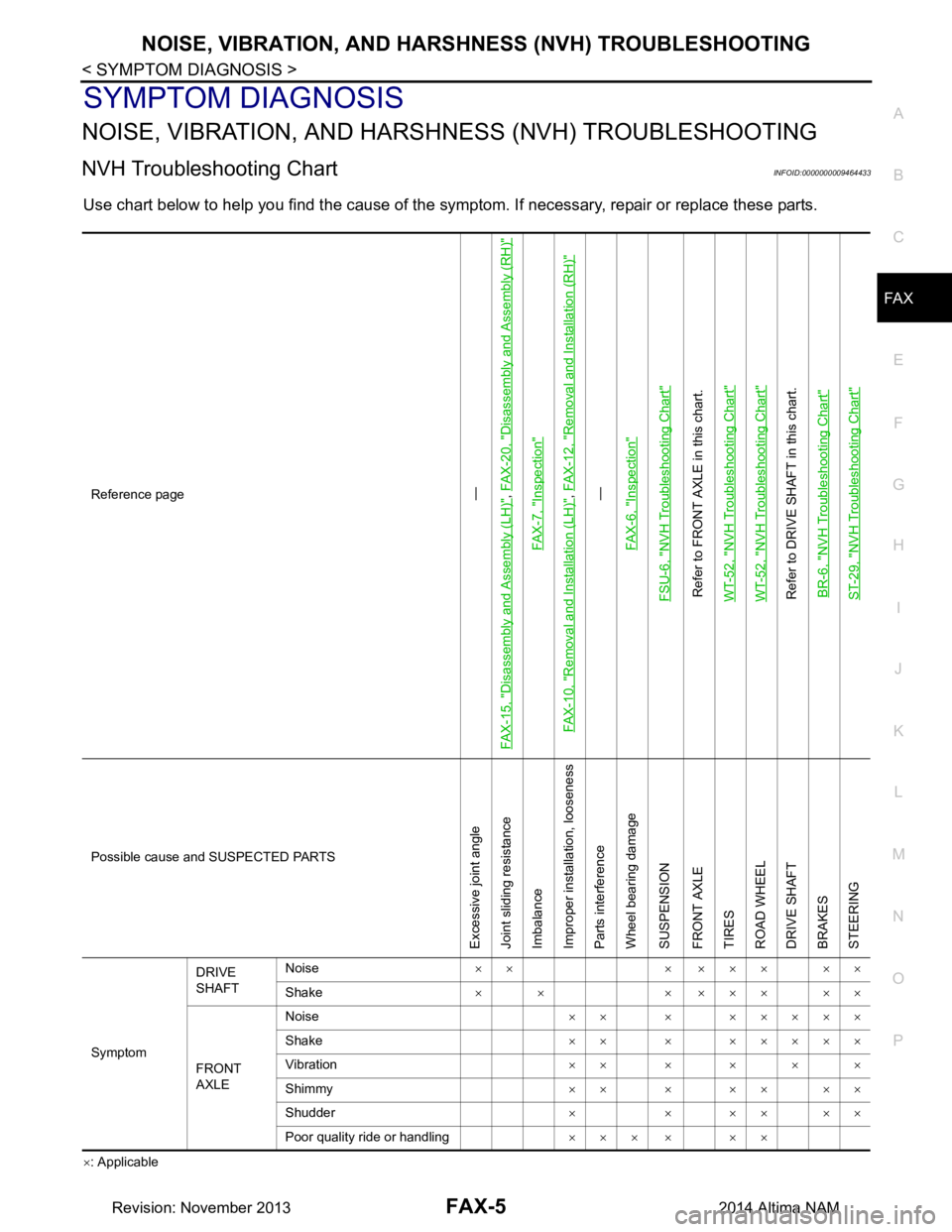
NOISE, VIBRATION, AND HARSHNESS (N VH) TROUBLESHOOTING
NVH Troubleshooting ChartINFOID:0000000009464433
Use chart below to help you find the cause of the symptom. If necessary, repair or replace these parts.
×: ApplicableReference page
—
FAX-15, "Disassembly and Assembly (LH)", FAX-20, "Disassembly and Assembly (RH)"
FAX-7, "Inspection"
FAX-10, "Removal and Installation (LH)"
, FAX-12, "Removal and Installation (RH)"—
FAX-6, "Inspection"
FSU-6, "NVH Troubleshooting Chart"Refer to FRONT AXLE in this chart.
WT-52, "NVH Troubleshooting Chart"WT-52, "NVH Troubleshooting Chart"Refer to DRIVE SHAFT in this chart. BR-6, "NVH Troubleshooting Chart"ST-29, "NVH Troubleshooting Chart"
Possible cause and SUSPECTED PARTS
Excessive joint angle
Joint sliding resistance
Imbalance
Improper installation, looseness
Parts interference
Wheel bearing damage
SUSPENSION
FRONT AXLE
TIRES
ROAD WHEEL
DRIVE SHAFT
BRAKES
STEERING
Symptom DRIVE
SHAFT Noise
×× × ××× ××
Shake × × × ××× ××
FRONT
AXLE Noise
×× × ×××××
Shake ×× × ×××××
Vibration ××××××
Shimmy ×××××××
Shudder ××××××
Poor quality ride or handling ××× × ××
Revision: November 20132014 Altima NAM
Page 2507 of 4801

FSU-6
< SYMPTOM DIAGNOSIS >
NOISE, VIBRATION AND HARSHNESS (NVH) TROUBLESHOOTING
SYMPTOM DIAGNOSIS
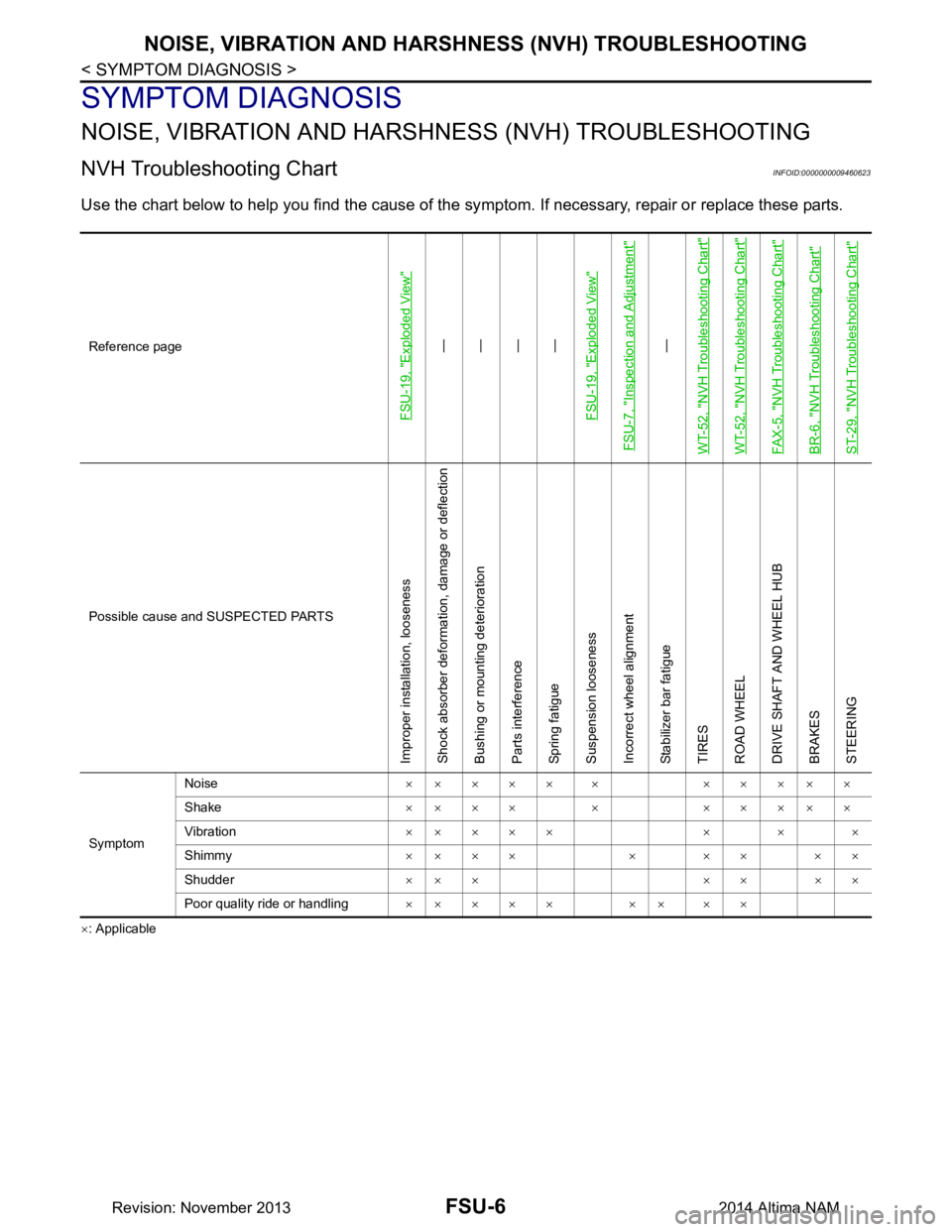
NOISE, VIBRATION AND HARSHNESS (NVH) TROUBLESHOOTING
NVH Troubleshooting ChartINFOID:0000000009460623
Use the chart below to help you find the cause of the sy mptom. If necessary, repair or replace these parts.
×: ApplicableReference page
FSU-19, "Exploded View"
—
—
—
—
FSU-19, "Exploded View"
FSU-7, "Inspection and Adjustment"
—
WT-52, "NVH Troubleshooting Chart"
WT-52, "NVH Troubleshooting Chart"FAX-5, "NVH Troubleshooting Chart"BR-6, "NVH Troubleshooting Chart"ST-29, "NVH Troubleshooting Chart"
Possible cause and SUSPECTED PARTS
Improper installation, looseness Shock absorber deformation, damage or deflection
Bushing or mounting deterioration
Parts interference
Spring fatigue
Suspension looseness
Incorrect wheel alignment
Stabilizer bar fatigue
TIRES
ROAD WHEEL
DRIVE SHAFT AND WHEEL HUB
BRAKES
STEERING
Symptom Noise
××××× × ×××××
Shake ×××× × ×××××
Vibration ×× × × × × × ×
Shimmy ×× × × × × × × ×
Shudder ×× × × × × ×
Poor quality ride or handling ×× × × × ×× × ×
Revision: November 20132014 Altima NAM