engine coolant NISSAN TEANA 2014 Service Manual
[x] Cancel search | Manufacturer: NISSAN, Model Year: 2014, Model line: TEANA, Model: NISSAN TEANA 2014Pages: 4801, PDF Size: 51.2 MB
Page 6 of 4801

< SERVICE DATA AND SPECIFICATIONS (SDS) 2014
QUICK REFERENCE CHART: ALTIMA
*1: Fuel, engine coolant, and lubricants are full. Spare tire, jack, hand tools, and mats are in designated positions.
*2: The RH camber angle shall be -0
° 15 ′± 0 ° 33 ′ (-0.25 °± 0.55° ) with respect to the LH camber angle.
*3: For the caster angle, the difference between right and left against the ground surface shall be ± 0 ° 30 ′ ( ± 0.50° ) maximum.
CANADA
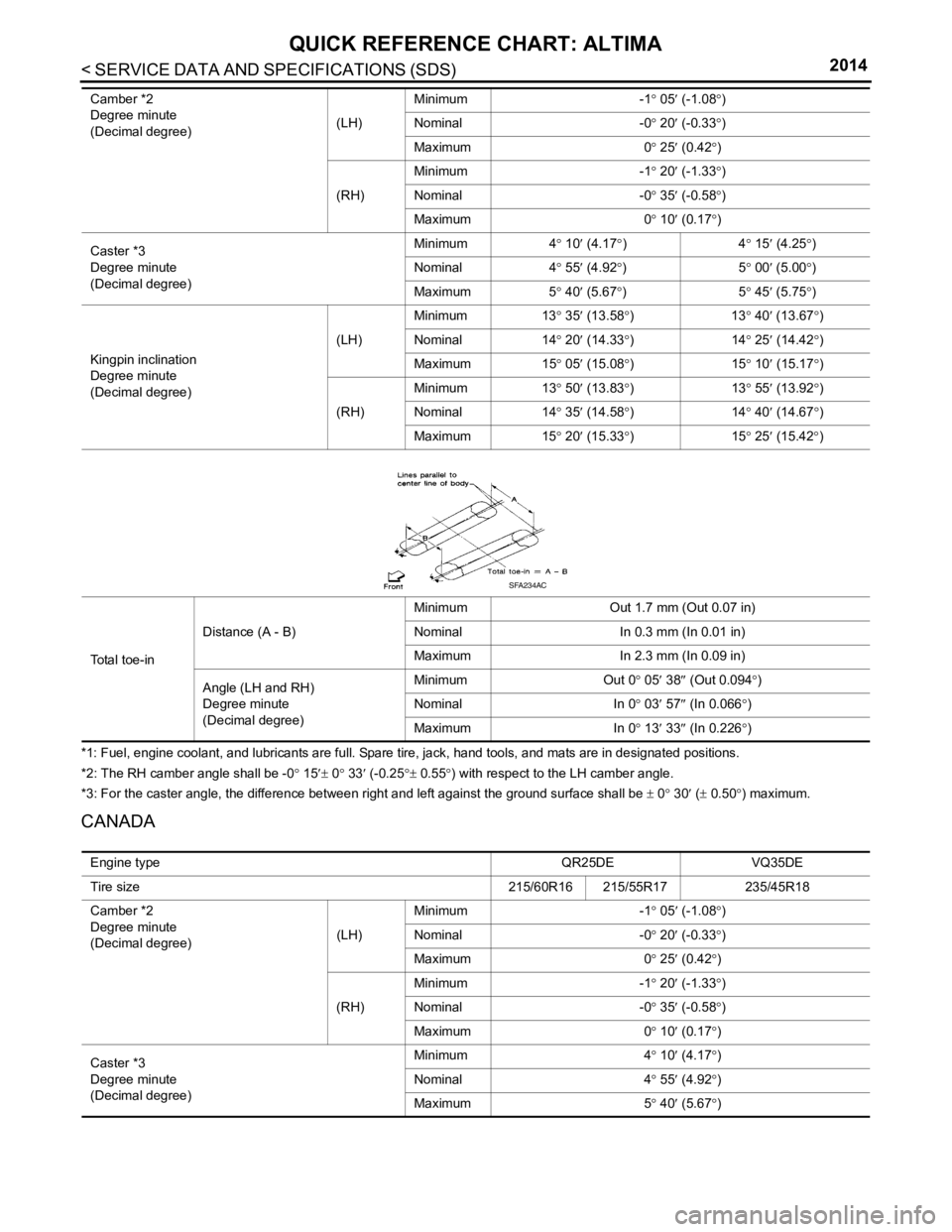
Camber *2
Degree minute
(Decimal degree) (LH)Minimum
-1° 05 ′ (-1.08 °)
Nominal -0° 20 ′ (-0.33 °)
Maximum 0° 25 ′ (0.42 °)
(RH) Minimum
-1° 20 ′ (-1.33 °)
Nominal -0° 35 ′ (-0.58 °)
Maximum 0° 10 ′ (0.17 °)
Caster *3
Degree minute
(Decimal degree) Minimum
4° 10 ′ (4.17 °)4 ° 15 ′ (4.25 °)
Nominal 4° 55 ′ (4.92 °)5 ° 00 ′ (5.00 °)
Maximum 5° 40 ′ (5.67 °)5 ° 45 ′ (5.75 °)
Kingpin inclination
Degree minute
(Decimal degree) (LH)
Minimum
13° 35 ′ (13.58 °)1 3° 40 ′ (1
3.67 °)
Nominal 14° 20 ′ (14.33 °)1 4° 25 ′ (14.42 °)
Maximum 15° 05 ′ (15.08 °)1 5° 10 ′ (15.17 °)
(RH) Minimum
13° 50 ′ (13.83 °)1 3° 55 ′ (13.92 °)
Nominal 14° 35 ′ (14.58 °)1 4° 40 ′ (14.67 °)
Maximum 15° 20 ′ (15.33 °)1 5° 25 ′ (15.42 °)
Total toe-in Distance (A - B)
Minimum
Out 1.7 mm (Out 0.07 in)
Nominal In 0.3 mm (In 0.01 in)
Maximum In 2.3 mm (In 0.09 in)
Angle (LH and RH)
Degree minute
(Decimal degree) Minimum
Out 0° 05′ 38 ″ (Out 0.094° )
Nominal In 0° 03 ′ 57 ″ (In 0.066 °)
Maximum In 0° 13′ 33 ″ (In 0.2
26 °)
SFA234AC
Engine type QR25DEVQ35DE
Tire size 215/60R16 215/55R17235/45R18
Camber *2
Degree minute
(Decimal degree) (LH)Minimum
-1° 05 ′ (-1.08 °)
Nominal -0° 20 ′ (-0.33 °)
Maximum 0° 25 ′ (0.42 °)
(RH) Minimum
-1° 20 ′ (-1.33 °)
Nominal -0° 35 ′ (-0.58 °)
Maximum 0° 10 ′ (0.17 °)
Caster *3
Degree minute
(Decimal degree) Minimum
4° 10 ′ (4.17 °)
Nominal 4° 55 ′ (4.92 °)
Maximum 5° 40 ′ (5.67 °)
Page 7 of 4801

QUICK REFERENCE CHART: ALTIMA
2014
*1: Fuel, engine coolant, and lubricants are full. Spare tire, jack, hand tools, and mats are in designated positions.
*2: The RH camber angle shall be -0° 15 ′± 0 ° 33′ (-0.25 °± 0.55 °) with respect to the LH camber angle.
*3: For the caster angle, the difference between right and left against the ground surface shall be ± 0 ° 30 ′ ( ± 0.50 °) maximum.
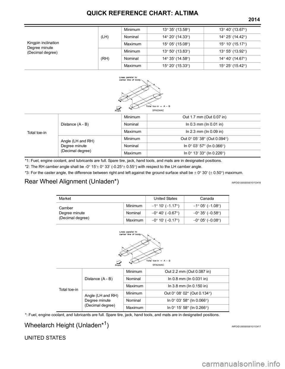
Rear Wheel Alignment (Unladen*)INFOID:0000000010112416
*: Fuel, engine coolant, and lubricants are full. Spare tire, jack, hand tools, and mats are in designated positions.
Wheelarch Height (Unladen*1)INFOID:0000000010112417
UNITED STATES
Kingpin inclination
Degree minute
(Decimal degree) (LH)
Minimum
13° 35 ′ (13.58 °)1 3° 40 ′ (13.67 °)
Nominal 14° 20 ′ (14.33 °)1 4° 25 ′ (14.42 °)
Maximum 15° 05 ′ (15.08 °)1 5° 10 ′ (15.17 °)
(RH) Minimum
13° 50 ′ (13.83 °)1 3° 55 ′ (13.92 °)
Nominal 14° 35 ′ (14.58 °)1 4° 40 ′ (14.67 °)
Maximum 15° 20 ′ (15.33 °)1 5° 25 ′ (15.42 °)
To t a l t o e - i n Distance (A - B)
Minimum
Out 1.7 mm (Out 0.07 in)
Nominal In 0.3 mm (In 0.01 in)
Maximum In 2.3 mm (In 0.09 in)
Angle (LH and RH)
Degree minute
(Decimal degree) Minimum
Out 0° 05 ′ 38 ″ (Out 0.094 °)
Nominal In 0° 03 ′ 57 ″ (I
n 0.066 °)
Maximum In 0° 13 ′ 33 ″ (In 0.226 °)
SFA234AC
Market United StatesCanada
Camber
Degree minute
(Decimal degree) Minimum
−1° 10 ′ ( −1.17 °) −1 ° 05 ′ ( −1.08° )
Nominal −0° 40 ′ ( −0.67 °) −0 ° 35 ′ ( −0.58° )
Maximum −0° 10 ′ ( −0.17 °) −0 ° 05 ′ ( −0.08° )
Total toe-in Distance (A - B)
Minimum
Out 2.2 mm (Out 0.087 in)
Nominal In 0.8 mm (In 0.031 in)
Maximum In 3.8 mm (In 0.150 in)
Angle (LH and RH)
Degree minute
(Decimal degree) Minimum
Out 0° 08′ 02 ″ (Out 0.134° )
Nominal In 0° 03 ′ 58 ″ (In 0.066 °)
Maximum In 0° 15′ 58 ″ (In 0.266 °)
SFA234AC
Page 8 of 4801

< SERVICE DATA AND SPECIFICATIONS (SDS) 2014
QUICK REFERENCE CHART: ALTIMA
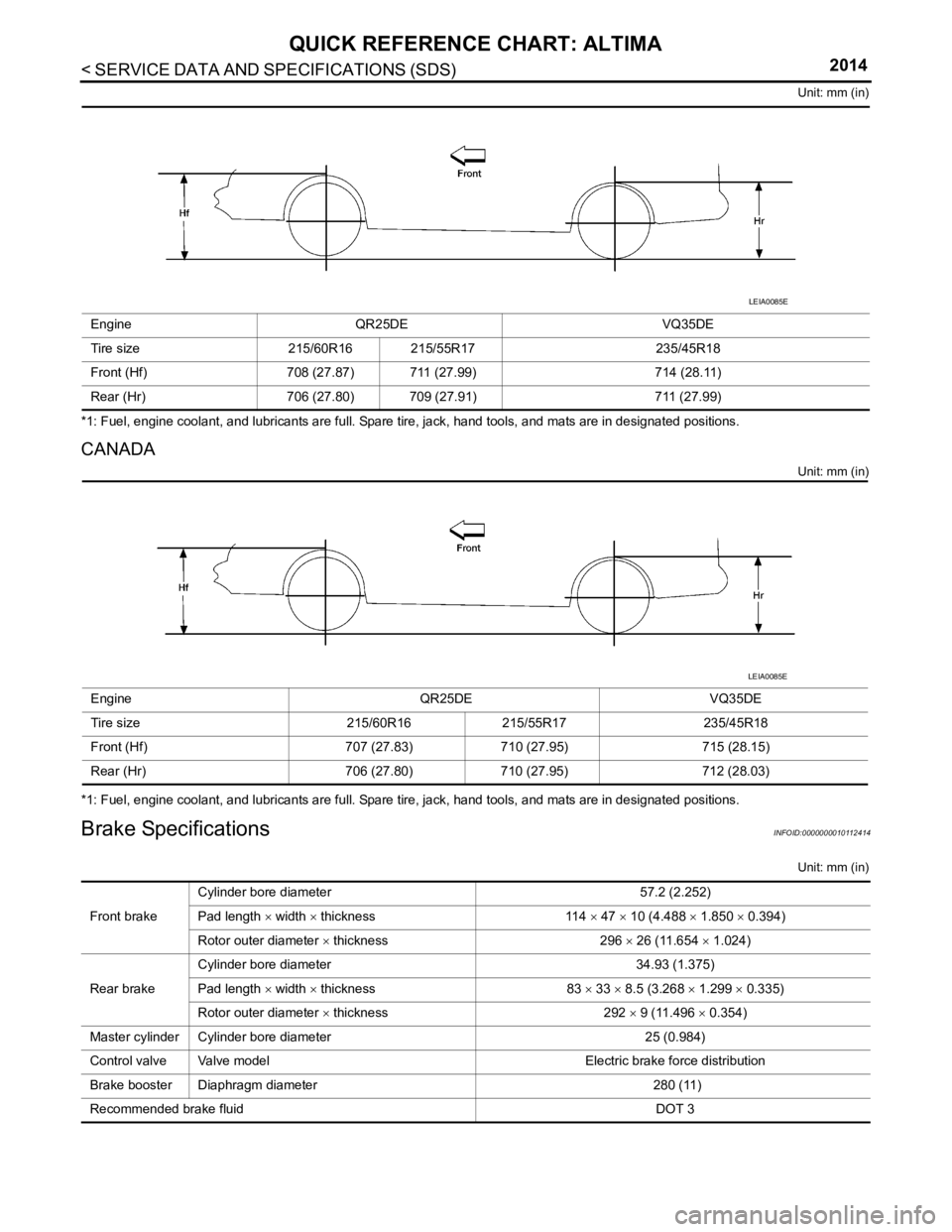
Unit: mm (in)
*1: Fuel, engine coolant, and lubricants are full. Spare tire, jack, hand tools, and mats are in designated positions.
CANADA
Unit: mm (in)
*1: Fuel, engine coolant, and lubricants are full. Spare tire, jack, hand tools, and mats are in designated positions.
Brake SpecificationsINFOID:0000000010112414
Unit: mm (in)
Engine
QR25DE VQ35DE
Tire size 215/60R16 215/55R17 235/45R18
Front (Hf) 708 (27.87) 711 (27.99) 714 (28.11)
Rear (Hr) 706 (27.80) 709 (27.91) 711 (27.99)
LEIA0085E
EngineQR25DEVQ35DE
Tire size 215/60R16215/55R17 235/45R18
Front (Hf) 707 (27.83)710 (27.95) 715 (28.15)
Rear (Hr) 706 (27.80)710 (27.95) 712 (28.03)
LEIA0085E
Front brakeCylinder bore diameter
57.2 (2.252)
Pad length × width × thickness 114 × 47 × 10 (4.488 × 1.850 × 0.394)
Rotor outer diameter × thickness 296 × 26 (11.654 × 1.024)
Rear brake Cylinder bore diameter
34.93 (1.375)
Pad length × width × thickness 83 × 33 × 8.5 (3.268 × 1.299 × 0.335)
Rotor outer diameter × thickness 292 × 9 (11.496 × 0.354)
Master cylinder Cylinder bore diameter 25 (0.984)
Control valve Valve model Electric brake force distribution
Brake booster Diaphragm diameter 280 (11)
Recommended brake fluid DOT 3
Page 378 of 4801

CHG
GENERATORCHG-33
< REMOVAL AND INSTALLATION >
C
D E
F
G H
I
J
K L
B
A
O P
N
• This model is equipped with a power generation voltage
variable control system. Therefore, perform an
inspection of the power generation voltage variable c ontrol system operation after replacing the generator.
Refer to CHG-10, "System Description"
.
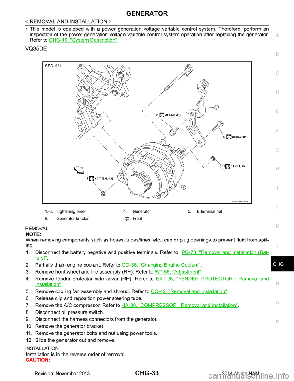
VQ35DE
REMOVAL
NOTE:
When removing components such as hoses, tubes/lines, etc. , cap or plug openings to prevent fluid from spill-
ing.
1. Disconnect the battery negative and positive terminals. Refer to PG-73, "Removal and Installation (Bat-
tery)".
2. Partially drain engine coolant. Refer to CO-36, "Changing Engine Coolant"
.
3. Remove front wheel and tire assembly (RH). Refer to WT-55, "Adjustment"
.
4. Remove fender protector side cover (RH). Refer to EXT-26, "FENDER PROTECTOR : Removal and
Installation".
5. Remove cooling fan assembly and shroud. Refer to CO-42, "Removal and Installation"
.
6. Release clip and reposition power steering tube.
7. Remove the A/C compressor. Refer to HA-30, "COMPRESSOR : Removal and Installation"
.
8. Disconnect oil pressure switch.
9. Disconnect the harness connectors from the generator.
10. Remove the generator bracket.
11. Remove the generator bolts and nut using power tools.
12. Slide the generator out and remove.
INSTALLATION
Installation is in the reverse order of removal.
CAUTION:
AWBIA1097GB
1.-3. Tightening order 4. Generator 5. B terminal nut
6. Generator bracket Front
Revision: November 20132014 Altima NAMRevision: November 20132014 Altima NAM
Page 381 of 4801

CO-1
ENGINE
C
D E
F
G H
I
J
K L
M
SECTION CO
A
CO
N
O P
CONTENTS
ENGINE COOLING SYSTEM
QR25DE
PRECAUTION ................ ...............................
3
PRECAUTIONS .............................................. .....3
Precaution for Supplemental Restraint System
(SRS) "AIR BAG" and "SEAT BELT PRE-TEN-
SIONER" ............................................................. ......
3
Precaution for Liquid Gasket .....................................3
PREPARATION ............................................5
PREPARATION .............................................. .....5
Special Service Tool ........................................... ......5
Commercial Service Tool ..........................................5
SYSTEM DESCRIPTION ..............................7
COOLING SYSTEM ....................................... .....7
Cooling Circuit ..................................................... ......7
Schematic .................................................................8
OVERHEATING CAUSE ANALYSIS ..................9
Troubleshooting Chart ...............................................9
PERIODIC MAINTENANCE .........................11
ENGINE COOLANT ....................................... ....11
System Inspection ............................................... ....11
Changing Engine Coolant .......................................12
REMOVAL AND INSTALLATION ...............16
RADIATOR ..................................................... ....16
Exploded View .................................................... ....16
Removal and Installation .........................................17
Inspection ............................................................ ....17
COOLING FAN ...................................................18
Exploded View .................................................... ....18
Removal and Installation .........................................18
WATER PUMP ............................................... ....20
Exploded View ..................................................... ....20
Removal and Installation .........................................20
THERMOSTAT AND THERMOSTAT HOUS-
ING ....................................................................
22
Exploded View ..................................................... ....22
Removal and Installation .........................................22
WATER OUTLET AND WATER PIPING ..........24
Exploded View .........................................................24
Removal and Installation .........................................24
SERVICE DATA AND SPECIFICATIONS
(SDS) ............... .............................................
26
SERVICE DATA AND SPECIFICATIONS
(SDS) .................................................................
26
Capacity ............................................................... ....26
Thermostat ..............................................................26
Radiator ...................................................................26
VQ35DE
PRECAUTION ...... ........................................
27
PRECAUTIONS .................................................27
Precaution for Supplemental Restraint System
(SRS) "AIR BAG" and "SEAT BELT PRE-TEN-
SIONER" ............................................................. ....
27
Precaution for Liquid Gasket ...................................27
PREPARATION ...........................................29
PREPARATION .................................................29
Special Service Tool ............................................ ....29
Commercial Service Tool ........................................29
SYSTEM DESCRIPTION .............................31
COOLING SYSTEM ..........................................31
Cooling Circuit ..................................................... ....31
Schematic ................................................................32
Revision: November 20132014 Altima NAM
Page 382 of 4801

CO-2
OVERHEATING CAUSE ANALYSIS ................33
Troubleshooting Chart ......................................... ...33
PERIODIC MAINTENANCE ..................... ...35
ENGINE COOLANT ........................................ ...35
System Inspection ............................................... ...35
Changing Engine Coolant .......................................36
REMOVAL AND INSTALLATION ...............40
RADIATOR ..................................................... ...40
Exploded View ..................................................... ...40
Removal and Installation ........................................41
Inspection ...............................................................41
COOLING FAN ..................................................42
Exploded View ..................................................... ...42
Removal and Installation ........................................42
WATER PUMP ...................................................44
Exploded View ..................................................... ...44
Removal and Installation .........................................44
THERMOSTAT AND THERMOSTAT HOUS-
ING .................................................................. ...
49
Exploded View ..................................................... ...49
Removal and Installation .........................................49
WATER OUTLET AND WATER PIPING ....... ...51
Exploded View ..................................................... ...51
Removal and Installation .........................................51
SERVICE DATA AND SPECIFICATIONS
(SDS) ............... ...........................................
53
SERVICE DATA AND SPECIFICATIONS
(SDS) .............................................................. ...
53
Capacity ............................................................... ...53
Thermostat ..............................................................53
Radiator ..................................................................53
Revision: November 20132014 Altima NAM
Page 384 of 4801
![NISSAN TEANA 2014 Service Manual
CO-4
< PRECAUTION >[QR25DE]
PRECAUTIONS
4. Apply the liquid gasket using suitable tool without breaks to the
specified location.
• If there is a groove for the liquid gasket application, apply the NISSAN TEANA 2014 Service Manual
CO-4
< PRECAUTION >[QR25DE]
PRECAUTIONS
4. Apply the liquid gasket using suitable tool without breaks to the
specified location.
• If there is a groove for the liquid gasket application, apply the](/img/5/57390/w960_57390-383.png)
CO-4
< PRECAUTION >[QR25DE]
PRECAUTIONS
4. Apply the liquid gasket using suitable tool without breaks to the
specified location.
• If there is a groove for the liquid gasket application, apply the
liquid gasket to the groove.
• As for the bolt holes, normally apply the liquid gasket inside the holes. If specified, it should be applied outside the holes.
Make sure to read the text of this manual.
• Within five minutes of the liquid gasket application, install the mating component.
• If the liquid gasket protrudes, wipe it off immediately.
• Do not retighten after the installation.
• After 30 minutes or more have passed from the installation, fill the engine with the specified oil and coolant. Refer to MA-11,
"FOR USA AND CANADA : Fluids and Lubricants".
CAUTION:
If there are more specific instruct ions in the procedures contained in this manual concerning liquid
gasket applicatio n, observe them.
EMA0622D
SEM159F
Revision: November 20132014 Altima NAM
Page 385 of 4801
![NISSAN TEANA 2014 Service Manual
PREPARATIONCO-5
< PREPARATION > [QR25DE]
C
D E
F
G H
I
J
K L
M A
CO
NP
O
PREPARATION
PREPARATION
Special Service ToolINFOID:0000000009460385
The actual shapes of the tools may differ from those illu NISSAN TEANA 2014 Service Manual
PREPARATIONCO-5
< PREPARATION > [QR25DE]
C
D E
F
G H
I
J
K L
M A
CO
NP
O
PREPARATION
PREPARATION
Special Service ToolINFOID:0000000009460385
The actual shapes of the tools may differ from those illu](/img/5/57390/w960_57390-384.png)
PREPARATIONCO-5
< PREPARATION > [QR25DE]
C
D E
F
G H
I
J
K L
M A
CO
NP
O
PREPARATION
PREPARATION
Special Service ToolINFOID:0000000009460385
The actual shapes of the tools may differ from those illustrated here.
Commercial Service ToolINFOID:0000000009460386
Tool number
(TechMate No.)
Tool name Description
EG17650301
(J-33984-A)
Radiator cap tester adapter Adapting radiator cap tester to radiator cap
and radiator filler neck
a: 28 (1.10) dia.
b: 31.4 (1.236) dia.
c: 41.3 (1.626) dia.
Unit: mm (in)
K V 1 0 1111 0 0
(J-37228)
Seal cutter Removing chain tensioner cover and water
pump cover
KV991J0070
(J-45695)
Coolant Refill Tool Refilling engine cooling system
—
(J-23688)
Engine coolant refractometer Checking concentration of ethylene glycol in
engine coolant
S-NT564
NT046
LMA053
WBIA0539E
Revision: November 20132014 Altima NAM
Page 389 of 4801
![NISSAN TEANA 2014 Service Manual
OVERHEATING CAUSE ANALYSISCO-9
< SYSTEM DESCRIPTION > [QR25DE]
C
D E
F
G H
I
J
K L
M A
CO
NP
O
OVERHEATING CAUSE ANALYSIS
Troubleshooting ChartINFOID:0000000009460389
Symptom Check items
Cooling sys NISSAN TEANA 2014 Service Manual
OVERHEATING CAUSE ANALYSISCO-9
< SYSTEM DESCRIPTION > [QR25DE]
C
D E
F
G H
I
J
K L
M A
CO
NP
O
OVERHEATING CAUSE ANALYSIS
Troubleshooting ChartINFOID:0000000009460389
Symptom Check items
Cooling sys](/img/5/57390/w960_57390-388.png)
OVERHEATING CAUSE ANALYSISCO-9
< SYSTEM DESCRIPTION > [QR25DE]
C
D E
F
G H
I
J
K L
M A
CO
NP
O
OVERHEATING CAUSE ANALYSIS
Troubleshooting ChartINFOID:0000000009460389
Symptom Check items
Cooling sys-
tem parts
malfunction Poor heat transfer
Water pump malfunction Worn or loose drive belt
—
Thermostat stuck closed Coolant circulation
Damaged fins Dust contamination or rock
clogging
Mechanical damage
Clogged radiator cooling
tube Excess foreign material
(rust, dirt, sand, etc.)
Reduced air flow Cooling fan does not oper-
ate
Engine cooling fans —
High resistance to fan rota-
tion
Damaged fan blades
Damaged radiator shroud — Radiator shroud —
Improper coolant mixture
ratio — Coolant viscosity —
Poor coolant quality — Periodic maintenance —
Insufficient coolant Coolant leaks Cooling hose
Loose clamp
Cracked hose
Water pump Poor sealing
Radiator cap Loose
Poor sealing
Radiator O-ring for damage, deterio-
ration or improper fitting
Cracked radiator tank
Cracked radiator core
Reservoir tank Cracked reservoir tank
Overflowing reservoir tank Exhaust gas leaks into cool-
ing system Cylinder head deterioration
Cylinder head gasket deteri-
oration
Revision: November 20132014 Altima NAM
Page 391 of 4801
![NISSAN TEANA 2014 Service Manual
ENGINE COOLANTCO-11
< PERIODIC MAINTENANCE > [QR25DE]
C
D E
F
G H
I
J
K L
M A
CO
NP
O
PERIODIC MAINTENANCE
ENGINE COOLANT
System InspectionINFOID:0000000009460390
WARNING:
Do not remove the radiato NISSAN TEANA 2014 Service Manual
ENGINE COOLANTCO-11
< PERIODIC MAINTENANCE > [QR25DE]
C
D E
F
G H
I
J
K L
M A
CO
NP
O
PERIODIC MAINTENANCE
ENGINE COOLANT
System InspectionINFOID:0000000009460390
WARNING:
Do not remove the radiato](/img/5/57390/w960_57390-390.png)
ENGINE COOLANTCO-11
< PERIODIC MAINTENANCE > [QR25DE]
C
D E
F
G H
I
J
K L
M A
CO
NP
O
PERIODIC MAINTENANCE
ENGINE COOLANT
System InspectionINFOID:0000000009460390
WARNING:
Do not remove the radiator cap when the engine is hot. Serious burns could occur from high-pressure
engine coolant escaping from the radiator. Wrap a thick cloth around the cap. Slowly push down and
turn it a quarter turn to allow built-up pressure to escape. Carefully remove the cap by pushing it down
and turning it all the way.
CHECKING COOLING SYSTEM HOSES
Check hoses for the following:
• Improper attachment
• Leaks
•Cracks
• Damage
• Loose connections
• Chafing
• Deterioration
CHECKING RESERVOIR LEVEL
• Check if the reservoir tank coolant level is within MIN to MAX when
the engine is cool.
• Adjust coolant level if it is too much or too little.
CHECKING COOLING SYSTEM FOR LEAKS
To check for leakage, apply pressure to the cooling system using
suitable tool (A) and Tool (B).
WARNING:
Do not remove the radiator cap wh en the engine is hot. Serious
burns could occur from high pressure coolant escaping from
the radiator.
CAUTION:
Higher pressure than specified may cause radiator damage.
CHECKING RADIATOR CAP
1. Inspect the radiator cap. • Replace the cap if the metal plunger cannot be seen around the edge of the black rubber gasket.
• Replace the cap if deposits of waxy residue or other foreign material are on the black rubber gasket or
the metal retainer.
NOTE:
Thoroughly wipe out the radiator filler neck to remove any waxy residue or foreign material.
SMA412B
Tool number : EG17650301 (J-33984-A)
Testing pressure : Refer to CO-26, "Radiator"
.
AWBIA0740ZZ
Revision: November 20132014 Altima NAM