flat tire NISSAN TEANA 2014 Service Manual
[x] Cancel search | Manufacturer: NISSAN, Model Year: 2014, Model line: TEANA, Model: NISSAN TEANA 2014Pages: 4801, PDF Size: 51.2 MB
Page 67 of 4801
![NISSAN TEANA 2014 Service Manual
BCS-52
< ECU DIAGNOSIS INFORMATION >[BCM]
BCM (BODY CONTROL MODULE)
DTC Index
INFOID:0000000009462019
NOTE: Details of time display
• CRNT: Displays when there is a malfunction now or after returni NISSAN TEANA 2014 Service Manual
BCS-52
< ECU DIAGNOSIS INFORMATION >[BCM]
BCM (BODY CONTROL MODULE)
DTC Index
INFOID:0000000009462019
NOTE: Details of time display
• CRNT: Displays when there is a malfunction now or after returni](/img/5/57390/w960_57390-66.png)
BCS-52
< ECU DIAGNOSIS INFORMATION >[BCM]
BCM (BODY CONTROL MODULE)
DTC Index
INFOID:0000000009462019
NOTE: Details of time display
• CRNT: Displays when there is a malfunction now or after returning to the normal condition until turning igni- tion switch OFF → ON again.
• 1 - 39: Displayed if any previous malfunction is present when current condition is normal. It increases like 1
→ 2 → 3...38 → 39 after returning to the normal condition whenever ignition switch OFF → ON. The counter
remains at 39 even if the number of cycles exceeds it . It is counted from 1 again when turning ignition switch
OFF → ON after returning to the normal condition if the malfunction is detected again.
5 • C1704: LOW PRESSURE FL
• C1705: LOW PRESSURE FR
• C1706: LOW PRESSURE RR
• C1707: LOW PRESSURE RL
• C1708: [NO DATA] FL
• C1709: [NO DATA] FR
• C1710: [NO DATA] RR
• C1711: [NO DATA] RL
• C1712: [CHECKSUM ERR] FL
• C1713: [CHECKSUM ERR] FR
• C1714: [CHECKSUM ERR] RR
• C1715: [CHECKSUM ERR] RL
• C1716: [PRESSDATA ERR] FL
• C1717: [PRESSDATA ERR] FR
• C1718: [PRESSDATA ERR] RR
• C1719: [PRESSDATA ERR] RL
• C1720: [CODE ERR] FL
• C1721: [CODE ERR] FR
• C1722: [CODE ERR] RR
• C1723: [CODE ERR] RL
• C1724: [BATT VOLT LOW] FL
• C1725: [BATT VOLT LOW] FR
• C1726: [BATT VOLT LOW] RR
• C1727: [BATT VOLT LOW] RL
• C1730: FLAT TIRE FL
• C1731: FLAT TIRE FR
• C1732: FLAT TIRE RR
• C1733: FLAT TIRE RL
• C1734: CONTROL UNIT
• C1735: IGNITION SIGNAL
6 • B2621: INSIDE ANTENNA
• B2622: INSIDE ANTENNA
7 B259A: ROOM LAMP FUSE
Priority DTC
CONSULT display Fail-safe
Intelligent Key
warning lamp ON Tire pressure
monitor warning lamp ON Reference page
No DTC is detected.
Further testing may be required. —— — —
U1000: CAN COMM CIRCUIT — — — BCS-68, "Description"
U1010: CONTROL UNIT (CAN) — — — BCS-69, "DTC Logic"
U0415: VEHICLE SPEED SIG — — —BCS-70, "Description"
B2190: NATS ANTENNA AMP×—— SEC-84, "Description"
B2191: DIFFERENCE OF KEY ×—— SEC-86, "Description"
B2192: ID DISCORD BCM-ECM ×—— SEC-87, "DTC Logic"
B2193: CHAIN OF BCM-ECM ×—— SEC-88, "DTC Logic"
B2195: ANTI SCANNING ×—— SEC-89, "DTC Logic"
Revision: November 20132014 Altima NAMRevision: November 20132014 Altima NAM
Page 69 of 4801
![NISSAN TEANA 2014 Service Manual
BCS-54
< ECU DIAGNOSIS INFORMATION >[BCM]
BCM (BODY CONTROL MODULE)
C1712: [CHECKSUM ERR] FL — —
×
WT-33, "DTC Logic"
C1713: [CHECKSUM ERR] FR — — ×
C1714: [CHECKSUM ERR] RR — — ×
C171 NISSAN TEANA 2014 Service Manual
BCS-54
< ECU DIAGNOSIS INFORMATION >[BCM]
BCM (BODY CONTROL MODULE)
C1712: [CHECKSUM ERR] FL — —
×
WT-33, "DTC Logic"
C1713: [CHECKSUM ERR] FR — — ×
C1714: [CHECKSUM ERR] RR — — ×
C171](/img/5/57390/w960_57390-68.png)
BCS-54
< ECU DIAGNOSIS INFORMATION >[BCM]
BCM (BODY CONTROL MODULE)
C1712: [CHECKSUM ERR] FL — —
×
WT-33, "DTC Logic"
C1713: [CHECKSUM ERR] FR — — ×
C1714: [CHECKSUM ERR] RR — — ×
C1715: [CHECKSUM ERR] RL — — ×
C1716: [PRESSDATA ERR] FL — — ×
WT-35, "DTC Logic"
C1717: [PRESSDATA ERR] FR — — ×
C1718: [PRESSDATA ERR] RR — — ×
C1719: [PRESSDATA ERR] RL — — ×
C1720: [CODE ERR] FL — — ×
WT-37, "DTC Logic"
C1721: [CODE ERR] FR — — ×
C1722: [CODE ERR] RR — — ×
C1723: [CODE ERR] RL — — ×
C1724: [BATT VOLT LOW] FL — — ×
WT-39, "DTC Logic"
C1725: [BATT VOLT LOW] FR — — ×
C1726: [BATT VOLT LOW] RR — — ×
C1727: [BATT VOLT LOW] RL — — ×
C1729: VHCL SPEED SIG ERR — — ×WT-41, "DTC Logic"
C1730: FLAT TIRE FL — — ×
WT-42, "DTC Logic"
C1731: FLAT TIRE FR — — ×
C1732: FLAT TIRE RR — — ×
C1733: FLAT TIRE RL — — ×
C1734: CONTROL UNIT — — ×WT-44, "DTC Logic"
C1735: IGNTION SIGNAL — — ×WT-46, "DTC Logic"
CONSULT display Fail-safe Intelligent Key
warning lamp
ON Tire pressure
monitor warning
lamp ON Reference page
Revision: November 20132014 Altima NAMRevision: November 20132014 Altima NAM
Page 214 of 4801
![NISSAN TEANA 2014 Service Manual
BRC-68
< DTC/CIRCUIT DIAGNOSIS >[VDC/TCS/ABS]
C1105, C1106, C1107,
C1108 WHEEL SENSOR
C1105, C1106, C1107, C1108 WHEEL SENSOR
DTC LogicINFOID:0000000009463772
DTC DETECTION LOGIC
DTC CONFIRMATION P NISSAN TEANA 2014 Service Manual
BRC-68
< DTC/CIRCUIT DIAGNOSIS >[VDC/TCS/ABS]
C1105, C1106, C1107,
C1108 WHEEL SENSOR
C1105, C1106, C1107, C1108 WHEEL SENSOR
DTC LogicINFOID:0000000009463772
DTC DETECTION LOGIC
DTC CONFIRMATION P](/img/5/57390/w960_57390-213.png)
BRC-68
< DTC/CIRCUIT DIAGNOSIS >[VDC/TCS/ABS]
C1105, C1106, C1107,
C1108 WHEEL SENSOR
C1105, C1106, C1107, C1108 WHEEL SENSOR
DTC LogicINFOID:0000000009463772
DTC DETECTION LOGIC
DTC CONFIRMATION PROCEDURE
1.CHECK SELF DIAGNOSTIC RESULT
With CONSULT.
1. Start engine and drive vehicle at approximately 21 km/h (13 MPH) or more for approximately 5 minutes.
2. Perform self diagnostic result.
Is DTC C1105, C1106, C1107 or C1108 detected?
YES >> Proceed to diagnosis procedure. Refer to BRC-68, "Diagnosis Procedure".
NO >> Inspection End.
Diagnosis ProcedureINFOID:0000000009463773
Regarding Wiring Diagram information, refer to BRC-47, "Wiring Diagram".
CAUTION:
Do not check between wheel sensor terminals.
1.CONFIRM DTC
With CONSULT
1. Perform self-diagnostic result of ABS and record all active DTCs.
2. Clear all DTCs.
3. Perform DTC confirmation procedure. Refer to BRC-68, "DTC Logic"
.
Does DTC C1105, C1106, C1107 or C1108 reset?
YES >> GO TO 2.
NO >> Refer to GI-43, "Intermittent Incident"
.
2.CHECK TIRE PRESSURE AND TIRE WEAR
Check tires for excessive wear and proper inflation. Refer to WT-53, "Inspection"
.
Is the inspection result normal?
YES >> GO TO 3.
NO >> Repair or replace as necessary.
3.CHECK WHEEL SENSOR
DTC Display Item Malfunction detected condition Possible causes
C1105 RR RH SENSOR-2 • When distance between rear wheel sensor RH and
rear wheel sensor RH rotor is large.
• When installation of rear wheel sensor RH or rear wheel sensor RH rotor is not normal.
• Wheel sensor
• ABS actuator and electric unit
(control unit)
• Sensor rotor
C1106 RR LH SENSOR-2
• When distance between rear wheel sensor LH and
rear wheel sensor LH rotor is large.
• When installation of rear wheel sensor LH or rear wheel sensor LH rotor is not normal.
C1107 FR RH SENSOR-2 • When distance between front wheel sensor RH
and front wheel sensor RH rotor is large.
• When installation of front wheel sensor RH or front wheel sensor RH rotor is not normal.
C1108 FR LH SENSOR-2 • When distance between front wheel sensor LH and
front wheel sensor LH rotor is large.
• When installation of front wheel sensor LH or front wheel sensor LH rotor is not normal.
Revision: November 20132014 Altima NAMRevision: November 20132014 Altima NAM
Page 222 of 4801
![NISSAN TEANA 2014 Service Manual
BRC-76
< DTC/CIRCUIT DIAGNOSIS >[VDC/TCS/ABS]
C1115 ABS SENSOR
[ABNORMAL SIGNAL]
C1115 ABS SENSOR [ABNORMAL SIGNAL]
DTC LogicINFOID:0000000009463782
DTC DETECTION LOGIC
DTC CONFIRMATION PROCEDURE
1 NISSAN TEANA 2014 Service Manual
BRC-76
< DTC/CIRCUIT DIAGNOSIS >[VDC/TCS/ABS]
C1115 ABS SENSOR
[ABNORMAL SIGNAL]
C1115 ABS SENSOR [ABNORMAL SIGNAL]
DTC LogicINFOID:0000000009463782
DTC DETECTION LOGIC
DTC CONFIRMATION PROCEDURE
1](/img/5/57390/w960_57390-221.png)
BRC-76
< DTC/CIRCUIT DIAGNOSIS >[VDC/TCS/ABS]
C1115 ABS SENSOR
[ABNORMAL SIGNAL]
C1115 ABS SENSOR [ABNORMAL SIGNAL]
DTC LogicINFOID:0000000009463782
DTC DETECTION LOGIC
DTC CONFIRMATION PROCEDURE
1.CHECK SELF DIAGNOSTIC RESULT
With CONSULT.
1. Start engine and drive vehicle at approximately 30 km /h (19 MPH) or more for approximately 1 minute.
2. Perform self diagnostic result.
Is DTC C1115 detected?
YES >> Proceed to diagnosis procedure. Refer to BRC-76, "Diagnosis Procedure".
NO >> Inspection End.
Diagnosis ProcedureINFOID:0000000009463783
Regarding Wiring Diagram information, refer to BRC-47, "Wiring Diagram".
CAUTION:
Do not check between wheel sensor terminals.
1.CONNECTOR INSPECTION
1. Disconnect ABS actuator and electric unit (contro l unit) connector E54 and wheel sensor connector of
wheel with DTC.
2. Check terminals for deformation, disconnection, looseness or damage.
Is the inspection result normal?
YES >> GO TO 2.
NO >> Repair or replace as necessary.
2.CHECK WHEEL SENSOR OUTPUT SIGNAL
1. Connect ABS active wheel sensor tester (J- 45741) to wheel sensor using appropriate adapter.
2. Turn on the ABS active wheel sensor tester power switch. NOTE:
The green POWER indicator should illuminate. If the POWER indicator does not illuminate, replace the
battery in the ABS active wheel sensor tester before proceeding.
3. Spin the wheel of the vehicle by hand and observe the red SENSOR indicator on the ABS active wheel
sensor tester. The red SENSOR indicator should flash on and off to indicate an output signal.
NOTE:
If the red SENSOR indicator illuminates but does not flash, reverse the polarity of the tester leads and
retest.
Does the ABS active wheel sensor tester detect a signal?
YES >> GO TO 3.
NO >> Replace the wheel sensor. Refer to BRC-124, "Removal and Installation - Front Wheel Sensor"
or
BRC-125, "Removal and Installation - Rear Wheel Sensor"
.
3.CHECK TIRES
Check the inflation pressure, wear and size of each tire.
Is the inspection result normal?
DTC Display Item Malfunction detected condition Possible causes
C 111 5 ABS SENSOR
[ABNORMAL SIGNAL] When difference in wheel speed between any wheel
and others is detected while the vehicle is driven, be-
cause of installation of tires other than specified. • Harness or connector
• Wheel sensor
• Sensor rotor
• ABS actuator and electric unit (control unit)
Revision: November 20132014 Altima NAMRevision: November 20132014 Altima NAM
Page 2388 of 4801
EXL-122
< PERIODIC MAINTENANCE >
HEADLAMP
PERIODIC MAINTENANCE
HEADLAMP
Aiming AdjustmentINFOID:0000000009463617
PREPARATION BEFORE ADJUSTING
Before performing aiming adjustment, check the following:
• Ensure all tires are inflated to correct pressure.
• Place vehicle and screen on level surface.
• Ensure there is no load in vehicle other than the driver (or equivalent weight placed in driver's position).
• Coolant and engine oil filled to correct level, and fuel tank full.
• Remove cargo and/or luggage to maintain an unloaded vehicle condition.
• Confirm spare tire, jack and tools are properly stowed.
• Carefully wipe off any dirt from headlamp lens. CAUTION:
Do not use organic solvent (thinner, gasoline etc.)
• Place a driver or equivalent weight of 68.5 kg (150 lb) on the driver seat.
• By hand, bounce the front and rear of the vehicle to settle the suspension and eliminate any static load.
• Place the front tires in the straight ahead position.
• Aim each headlamp individually and ensure other headlamp beam pattern is blocked from screen.
NOTE:
• For headlamp aiming details, refer to regulations in your area.
• By regulation, no means for horizontal aim adjustment is provided from the factory; only vertical aim is
adjustable.
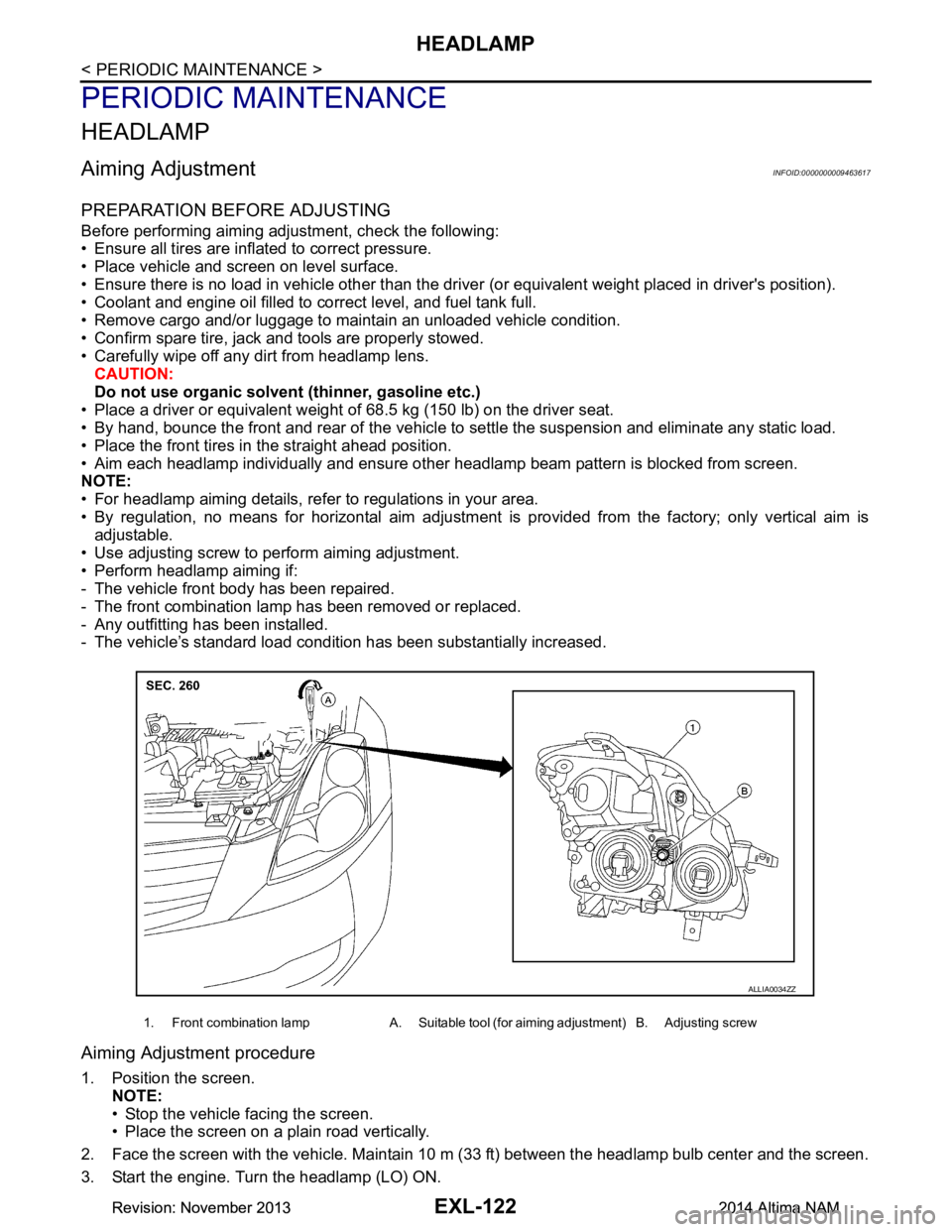
• Use adjusting screw to perform aiming adjustment.
• Perform headlamp aiming if:
- The vehicle front body has been repaired.
- The front combination lamp has been removed or replaced.
- Any outfitting has been installed.
- The vehicle’s standard load condition has been substantially increased.
Aiming Adjustment procedure
1. Position the screen.
NOTE:
• Stop the vehicle facing the screen.
• Place the screen on a plain road vertically.
2. Face the screen with the vehicle. Maintain 10 m (33 ft) between the headlamp bulb center and the screen.
3. Start the engine. Turn the headlamp (LO) ON.
1. Front combination lamp A. Suitable tool (for aiming adjustment) B. Adjusting screw
ALLIA0034ZZ
Revision: November 20132014 Altima NAMRevision: November 20132014 Altima NAM
Page 2390 of 4801
EXL-124
< PERIODIC MAINTENANCE >
FRONT FOG LAMP
FRONT FOG LAMP
Aiming AdjustmentINFOID:0000000009463618
PREPARATION BEFORE ADJUSTING
The fog lamp is a semi-sealed beam type which uses a replaceable halogen bulb. Before performing aiming
adjustment procedure, check the following:
• Ensure all tires are inflated to correct pressure.
• Place vehicle and screen on level surface.
• Ensure there is no load in vehicle other than the driver (or equivalent weight placed in driver's position).
• Coolant and engine oil filled to correct level, and fuel tank full.
• Remove cargo and/or luggage to maintain an unloaded vehicle condition.
• Confirm spare tire, jack and tools are properly stowed.
• Carefully wipe off any dirt from headlamp lens. CAUTION:
Do not use organic solvent (thinner, gasoline etc.)
• Place a driver or equivalent weight of 68.5 kg (150 lb) on the driver seat.
• By hand, bounce the front and rear of the vehicle to settle the suspension and eliminate any static load.
• Place the front tires in the straight ahead position.
• Aim each headlamp individually and ensure other headlamp beam pattern is blocked from screen.
NOTE:
• For headlamp aiming details, refer to regulations in your area.
• By regulation, no means for horizontal aim adjustment is provided from the factory; only vertical aim is
adjustable.
• Use adjusting screw to perform aiming adjustment.
• Perform headlamp aiming if:
- The vehicle front body has been repaired.
- The front combination lamp has been removed or replaced.
- Any outfitting has been installed.
- The vehicle’s standard load condition has been substantially increased.
Aiming Adjustment Procedure
1. Place the screen. NOTE:
• Stop the vehicle facing the wall.
• Place the board on a plain road vertically.
2. Face the vehicle with the screen. Maintain 7.62 m (25.0 ft) between the front fog lamp center and the
screen.
3. Start the engine. Turn the front fog lamp ON. NOTE:
Shut off the headlamp light with the board to prevent from illuminating the adjustment screen.
CAUTION:
Do not cover the lens surface with a tape etc. The lens is made of resin.
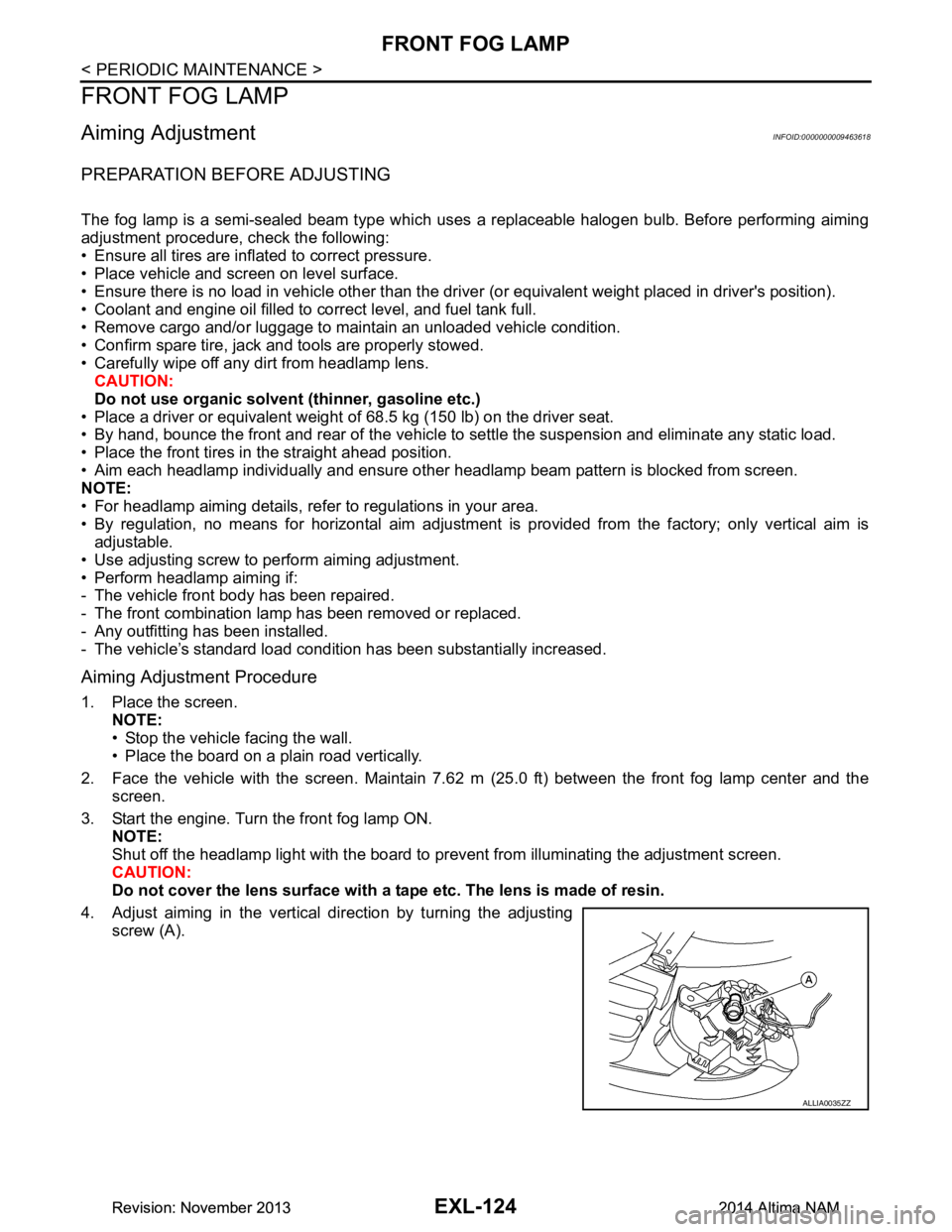
4. Adjust aiming in the vertical direction by turning the adjusting screw (A).
ALLIA0035ZZ
Revision: November 20132014 Altima NAMRevision: November 20132014 Altima NAM
Page 2503 of 4801
FSU-2
< PRECAUTION >
PRECAUTIONS
PRECAUTION
PRECAUTIONS
Precaution for Supplemental Restraint System (SRS) "AIR BAG" and "SEAT BELT
PRE-TENSIONER"
INFOID:0000000009951705
The Supplemental Restraint System such as “A IR BAG” and “SEAT BELT PRE-TENSIONER”, used along
with a front seat belt, helps to reduce the risk or severi ty of injury to the driver and front passenger for certain
types of collision. Information necessary to service the system safely is included in the SR and SB section of
this Service Manual.
WARNING:
• To avoid rendering the SRS inopera tive, which could increase the risk of personal injury or death in
the event of a collision which would result in air bag inflation, all maintenance must be performed by
an authorized NISS AN/INFINITI dealer.
• Improper maintenance, including in correct removal and installation of the SRS, can lead to personal
injury caused by unintent ional activation of the system. For re moval of Spiral Cable and Air Bag
Module, see the SR section.
• Do not use electrical test equipmen t on any circuit related to the SRS unless instructed to in this
Service Manual. SRS wiring harn esses can be identified by yellow and/or orange harnesses or har-
ness connectors.
PRECAUTIONS WHEN USING POWER TOOLS (AIR OR ELECTRIC) AND HAMMERS
WARNING:
• When working near the Airbag Diagnosis Sensor Unit or other Airbag System sensors with the Igni-
tion ON or engine running, DO NOT use air or electri c power tools or strike near the sensor(s) with a
hammer. Heavy vibration could activate the sensor( s) and deploy the air bag(s), possibly causing
serious injury.
• When using air or electric power tools or hammers , always switch the Ignition OFF, disconnect the
battery and wait at least three minutes before performing any service.
General PrecautionsINFOID:0000000009460620
• When installing rubber bushings, the final tightening mu st be carried out under unladen conditions with tires
on ground. Oil might shorten the life of rubber bushings. Be sure to wipe off any spilled oil.
- Unladen conditions mean that fuel, engine coolant and lubricant are full. Spare tire, jack, hand tools and mats are in designated positions.
• After servicing suspension parts, be sure to check wheel alignment.
• Self-lock nuts are not reusable. Always use new ones when installing. Since new self-lock nuts are pre-oiled,
tighten as they are.
Precaution for Procedure without Cowl Top CoverINFOID:0000000009460621
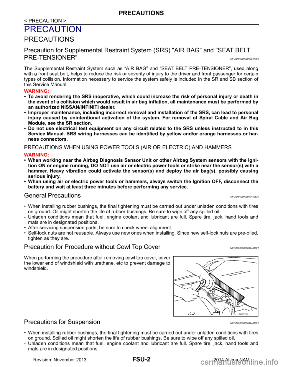
When performing the procedure after removing cowl top cover, cover
the lower end of windshield with urethane, etc to prevent damage to
windshield.
Precautions for SuspensionINFOID:0000000009460622
• When installing rubber bushings, the final tightening mu st be carried out under unladen conditions with tires
on ground. Spilled oil might shorten the life of rubber bushings. Be sure to wipe off any spilled oil.
- Unladen conditions mean that fuel, engine coolant and lubricant are full. Spare tire, jack, hand tools and mats are in designated positions.
PIIB3706J
Revision: November 20132014 Altima NAM
Page 3222 of 4801
MA-38
< PERIODIC MAINTENANCE >
CHASSIS AND BODY MAINTENANCE
CAUTION:
Do not reuse O-ring.
14. Lift down the vehicle.
15. Stop the engine.
WHEELS
WHEELS : InspectionINFOID:0000000009464574
ALUMINUM WHEEL
1. Check tires for wear and improper inflation.
2. Check wheels for deformation, cracks and other dam age. If deformed, remove wheel and check wheel
runout.
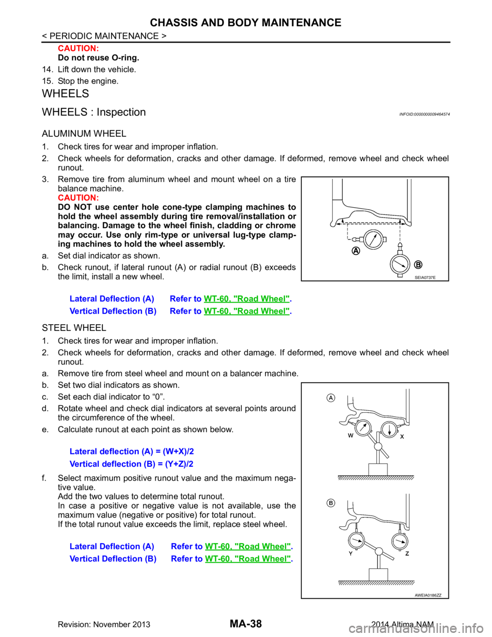
3. Remove tire from aluminum wheel and mount wheel on a tire balance machine.
CAUTION:
DO NOT use center hole cone -type clamping machines to
hold the wheel assembly during tire removal/installation or
balancing. Damage to the wheel finish, cladding or chrome
may occur. Use only rim-type or universal lug-type clamp-
ing machines to hold the wheel assembly.
a. Set dial indicator as shown.
b. Check runout, if lateral runout (A) or radial runout (B) exceeds the limit, install a new wheel.
STEEL WHEEL
1. Check tires for wear and improper inflation.
2. Check wheels for deformation, cracks and other dam age. If deformed, remove wheel and check wheel
runout.
a. Remove tire from steel wheel and mount on a balancer machine.
b. Set two dial indicators as shown.
c. Set each dial indicator to “0”.
d. Rotate wheel and check dial indicators at several points around the circumference of the wheel.
e. Calculate runout at each point as shown below.
f. Select maximum positive runout value and the maximum nega- tive value.
Add the two values to determine total runout.
In case a positive or negative value is not available, use the
maximum value (negative or positive) for total runout.
If the total runout value exceeds the limit, replace steel wheel. Lateral Deflection (A) Refer to
WT-60, "Road Wheel"
.
Vertical Deflection (B) Refer to WT-60, "Road Wheel"
.
SEIA0737E
Lateral deflection (A) = (W+X)/2
Vertical deflection (B) = (Y+Z)/2
Lateral Deflection (A) Refer to WT-60, "Road Wheel"
.
Vertical Deflection (B) Refer to WT-60, "Road Wheel"
.
AWEIA0186ZZ
Revision: November 20132014 Altima NAM
Page 3271 of 4801

MWI-16
< SYSTEM DESCRIPTION >
SYSTEM
The LOOSE FUEL CAP message will display in the information display when the fuel-filler cap is not tightened
correctly. The message will turn off as soon as the EC M detects the fuel-filler cap is properly tightened. The
ECM provides a loose fuel cap signal to the combination meter via CAN communication.
LOW TIRE PRESSURE WARNING
This warning appears when the BCM detects low inflati on pressure or a system malfunction. The BCM sends
a signal to the combination meter via CAN communication to illuminate the low tire pressure warning lamp. In
addition, a warning message will be displayed in the vehicle information display.
DOOR OPEN WARNING
This warning appears when the ignition switch is ON and the door is open. The BCM receives a door switch
signal from the door open door switch. The BCM sends t he door switch signal to the combination meter via
CAN communication lines.
TRUNK OPEN WARNING
This warning appears when the ignition switch is ON and the trunk is opened. The BCM receives a trunk lamp
switch signal from the trunk lamp switch. The BCM s ends the trunk lamp switch signal to the combination
meter via CAN communication.
LOW FUEL WARNING
This warning appears when the fuel level in the fuel tank is less than approximately 4 US gal (15 L, 3.3 Imp
gal). A variable resistor signal is supplied to the combi nation meter from the fuel level sensor unit to determine
the amount of fuel in the fuel tank.
LOW WINDSHIELD WASHER FLUID WARNING
When the windshield washer fluid level is low, the was her fluid level switch provides a ground signal to the
combination meter and the warning is displayed. Once fluid is added, the switch opens and the warning is no
longer displayed.
RELEASE PARKING BRAKE WARNING
When the parking brake is applied, the parking brake switch provides a ground signal to the combination
meter. When the vehicle speed is greater than 4 MPH (7 km/h), the message is displayed and the warning
chime sounds.
SHIFT POSITION INDICATOR
Displays the position of the shift selector based on signals received from TCM via CAN communication.
LOW OIL PRESSURE WARNING
The low oil pressure warning appears in the information display when the combination meter receives a low
engine oil pressure signal from the ECM via CAN communication.
WARNING CHECK INDICATION
The combination meter can cause an interrupt on the information display to indicate a warning, based on sig-
nals received from each unit and switch.
Refer to Owner’s Manual for additional information display items.
COMPASS
COMPASS : DescriptionINFOID:0000000009461691
DESCRIPTION
With the ignition switch in the ON position, and the mode (N) switch
ON, the compass display will indicate the direction the vehicle is
heading.
Vehicle direction is displayed as follows:
• N: north
• E: east
• S: south
•W: west
LKIA0447E
Revision: November 20132014 Altima NAMRevision: November 20132014 Altima NAM
Page 3342 of 4801
PB-4
< BASIC INSPECTION >
PARKING BRAKE SYSTEM
BASIC INSPECTION
PARKING BRAKE SYSTEM
InspectionINFOID:0000000009462912
PEDAL STROKE
1. Operate parking brake pedal with a force of 196 N (20.0 kg-f, 44.1 lb-f), make sure pedal stroke is within
the specified number of notches. (Check it by listening and counting ratchet clicks.)
2. When brake warning lamp turns ON, check that the pedal stroke is within the specified number of notches. (Check it by listening to the clicks of the ratchet.)
INSPECT COMPONENTS
• Make sure that the mounting conditions (loosenes s, backlash, etc.) of each component are normal.
• Check the following:
- Device assembly for bend, damage and cracks. Replace if necessary.
- Cables and equalizer for wear and damage. Replace if necessary.
- Parking brake switch. Replace if necessary.
AdjustmentINFOID:0000000009462913
ADJUSTMENT
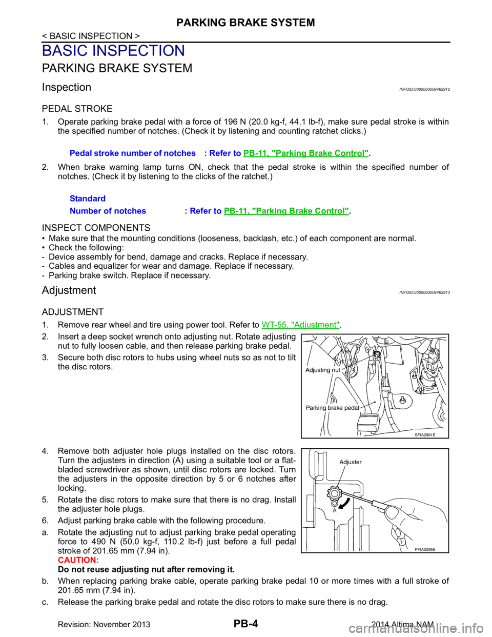
1. Remove rear wheel and tire using power tool. Refer to WT-55, "Adjustment".
2. Insert a deep socket wrench onto adjusting nut. Rotate adjusting nut to fully loosen cable, and then release parking brake pedal.
3. Secure both disc rotors to hubs using wheel nuts so as not to tilt the disc rotors.
4. Remove both adjuster hole plugs installed on the disc rotors. Turn the adjusters in direction (A) using a suitable tool or a flat-
bladed screwdriver as shown, until disc rotors are locked. Turn
the adjusters in the opposite direction by 5 or 6 notches after
locking.
5. Rotate the disc rotors to make sure that there is no drag. Install the adjuster hole plugs.
6. Adjust parking brake cable with the following procedure.
a. Rotate the adjusting nut to adjust parking brake pedal operating force to 490 N (50.0 kg-f, 110.2 lb-f) just before a full pedal
stroke of 201.65 mm (7.94 in).
CAUTION:
Do not reuse adjusting nut after removing it.
b. When replacing parking brake cable, operate parking brake pedal 10 or more times with a full stroke of 201.65 mm (7.94 in).
c. Release the parking brake pedal and rotate the disc rotors to make sure there is no drag. Pedal stroke number of notches : Refer to
PB-11, "Parking Brake Control"
.
Standard
Number of notches : Refer to PB-11, "Parking Brake Control"
.
SFIA2961E
PFIA0295E
Revision: November 20132014 Altima NAM