steering NISSAN TERRANO 2002 Service User Guide
[x] Cancel search | Manufacturer: NISSAN, Model Year: 2002, Model line: TERRANO, Model: NISSAN TERRANO 2002Pages: 1767, PDF Size: 41.51 MB
Page 1135 of 1767
2. Move the following parts.
ITDC sensor harness
IPower steering oil pump
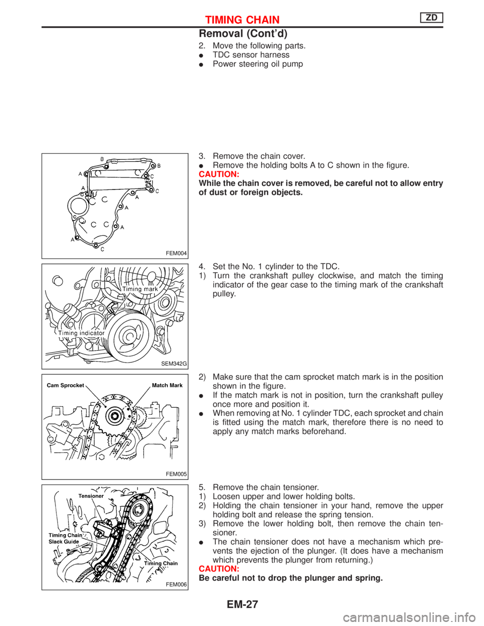
3. Remove the chain cover.
IRemove the holding bolts A to C shown in the figure.
CAUTION:
While the chain cover is removed, be careful not to allow entry
of dust or foreign objects.
4. Set the No. 1 cylinder to the TDC.
1) Turn the crankshaft pulley clockwise, and match the timing
indicator of the gear case to the timing mark of the crankshaft
pulley.
2) Make sure that the cam sprocket match mark is in the position
shown in the figure.
IIf the match mark is not in position, turn the crankshaft pulley
once more and position it.
IWhen removing at No. 1 cylinder TDC, each sprocket and chain
is fitted using the match mark, therefore there is no need to
apply any match marks beforehand.
5. Remove the chain tensioner.
1) Loosen upper and lower holding bolts.
2) Holding the chain tensioner in your hand, remove the upper
holding bolt and release the spring tension.
3) Remove the lower holding bolt, then remove the chain ten-
sioner.
IThe chain tensioner does not have a mechanism which pre-
vents the ejection of the plunger. (It does have a mechanism
which prevents the plunger from returning.)
CAUTION:
Be careful not to drop the plunger and spring.
FEM004
SEM342G
FEM005
FEM006
TIMING CHAINZD
Removal (Cont'd)
EM-27
Page 1172 of 1767
Engine room (Left)
3. Remove air duct and air cleaner case.
4. Disconnect vacuum hose to the vehicle on the engine.
5. Disconnect harness connectors from alternator and air com-
pressor.
6. Remove alternator.
7. After removing refrigerant, remove pipes of air compressor and
inlet/outlet.
8. Disconnect heating hose, install blank cap to hose to prevent
coolant from leaking.
9. Remove heating pipe.
10. Remove heat insulator.
11. Remove catalytic converter.
Engine room (Right)
12. Remove power steering reservoir tank from bracket, and fix it
to the vehicle with a rope.
CAUTION:
Keep the reservoir tank level when fixing to prevent oil leak.
13. Remove fuel feed and return hoses.
CAUTION:
Install blank caps immediately to avoid fuel leakage.
14. Remove all harness connectors on the engine, and move har-
nesses to the side of the vehicle.
Vehicle underfloor
15. Remove starter motor.
16. Detach A/T oil cooler pipes from oil pan. (A/T model)
17. Remove rear propeller shaft.
18. Remove mounting bolts to secure the engine to transmission.
1) Remove torque converter installation bolt. (A/T model)
2) Lift transmission bottom with transmission jack, and remove
rear mount members from the vehicle.
3) Lower transmission with the jack, and remove upper mounting
bolts securing the engine to transmission.
4) Lift transmission with the jack, and reinstall rear mount mem-
bers to the vehicle.
5) Position the jack to the front side of transmission.
6) Remove remaining mounting bolts securing the engine to trans-
mission.
Removal operation
19. Remove air conditioner high pressure pipes at the rear of the
engine room.
IThis is due to some inconvenience in the rear slinger installa-
tion.
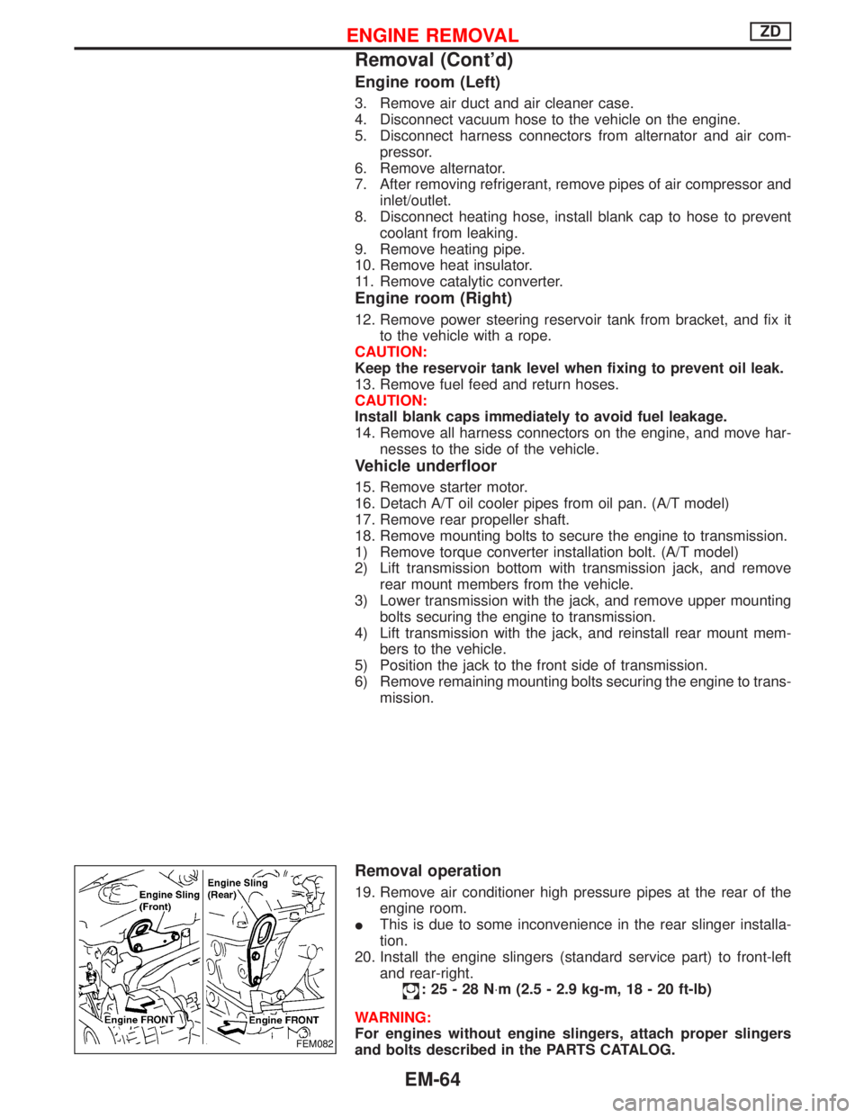
20. Install the engine slingers (standard service part) to front-left
and rear-right.
:25-28N×m (2.5 - 2.9 kg-m, 18 - 20 ft-lb)
WARNING:
For engines without engine slingers, attach proper slingers
and bolts described in the PARTS CATALOG.
FEM082
ENGINE REMOVALZD
Removal (Cont'd)
EM-64
Page 1266 of 1767
Front Wheel Alignment
Before checking front wheel alignment, be sure to make a prelimi-
nary inspection.
PRELIMINARY INSPECTION
1. Check the tires for wear and proper inflation.
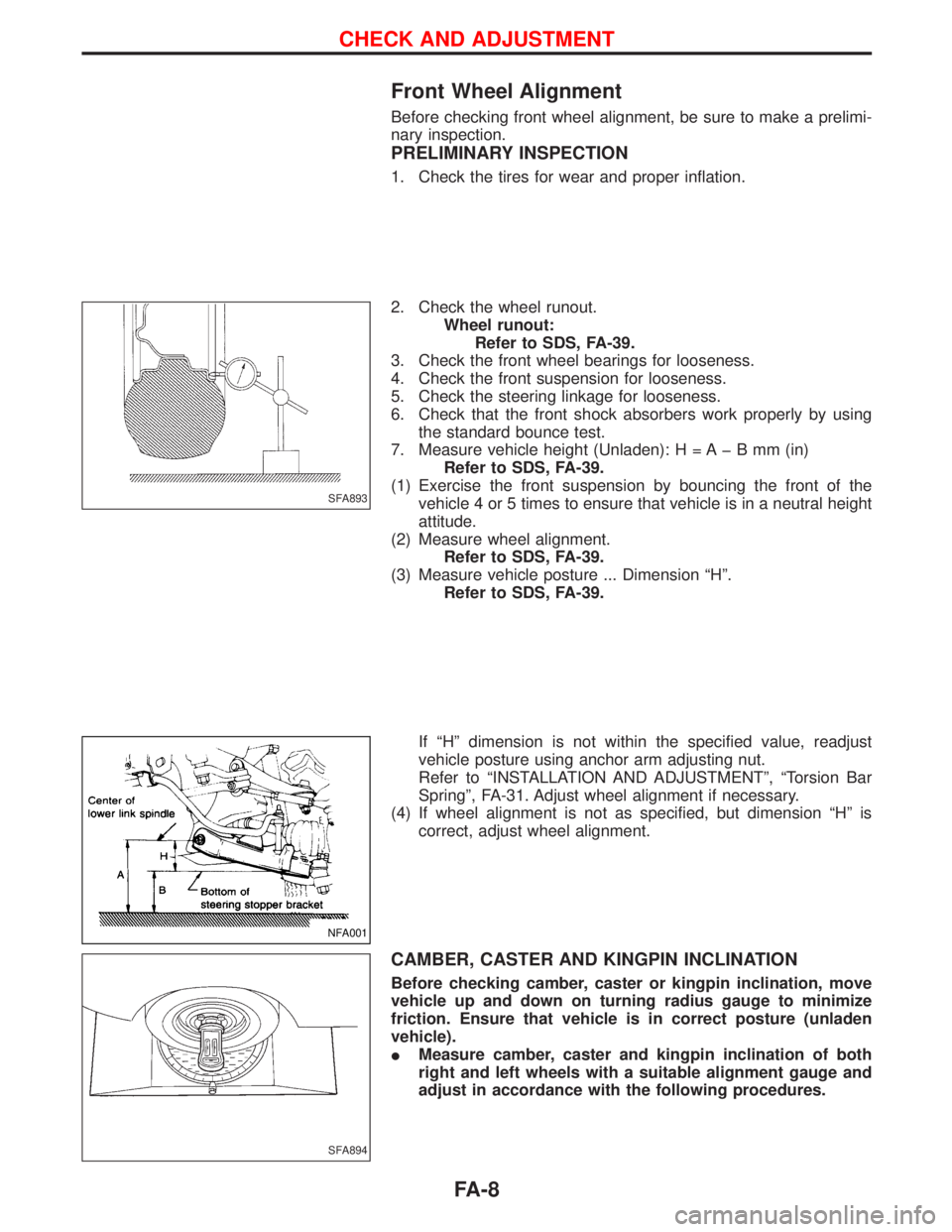
2. Check the wheel runout.
Wheel runout:
Refer to SDS, FA-39.
3. Check the front wheel bearings for looseness.
4. Check the front suspension for looseness.
5. Check the steering linkage for looseness.
6. Check that the front shock absorbers work properly by using
the standard bounce test.
7. Measure vehicle height (Unladen): H = A þ B mm (in)
Refer to SDS, FA-39.
(1) Exercise the front suspension by bouncing the front of the
vehicle 4 or 5 times to ensure that vehicle is in a neutral height
attitude.
(2) Measure wheel alignment.
Refer to SDS, FA-39.
(3) Measure vehicle posture ... Dimension ªHº.
Refer to SDS, FA-39.
If ªHº dimension is not within the specified value, readjust
vehicle posture using anchor arm adjusting nut.
Refer to ªINSTALLATION AND ADJUSTMENTº, ªTorsion Bar
Springº, FA-31. Adjust wheel alignment if necessary.
(4) If wheel alignment is not as specified, but dimension ªHº is
correct, adjust wheel alignment.
CAMBER, CASTER AND KINGPIN INCLINATION
Before checking camber, caster or kingpin inclination, move
vehicle up and down on turning radius gauge to minimize
friction. Ensure that vehicle is in correct posture (unladen
vehicle).
IMeasure camber, caster and kingpin inclination of both
right and left wheels with a suitable alignment gauge and
adjust in accordance with the following procedures.
SFA893
NFA001
SFA894
CHECK AND ADJUSTMENT
FA-8
Page 1269 of 1767
TOE-IN
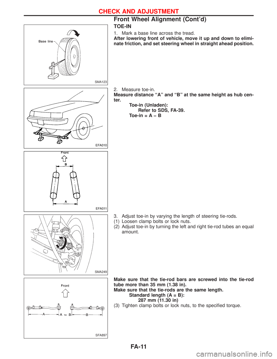
1. Mark a base line across the tread.
After lowering front of vehicle, move it up and down to elimi-
nate friction, and set steering wheel in straight ahead position.
2. Measure toe-in.
Measure distance ªAº and ªBº at the same height as hub cen-
ter.
Toe-in (Unladen):
Refer to SDS, FA-39.
Toe-in = A þ B
3. Adjust toe-in by varying the length of steering tie-rods.
(1) Loosen clamp bolts or lock nuts.
(2) Adjust toe-in by turning the left and right tie-rod tubes an equal
amount.
Make sure that the tie-rod bars are screwed into the tie-rod
tube more than 35 mm (1.38 in).
Make sure that the tie-rods are the same length.
Standard length (A = B):
287 mm (11.30 in)
(3) Tighten clamp bolts or lock nuts, to the specified torque.
SMA123
EFA010
EFA011
SMA249
SFA897
CHECK AND ADJUSTMENT
Front Wheel Alignment (Cont'd)
FA-11
Page 1270 of 1767
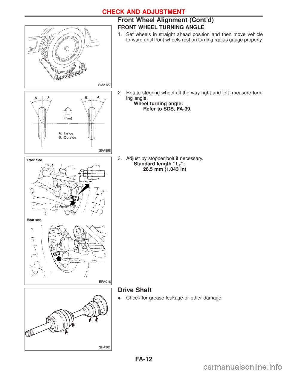
FRONT WHEEL TURNING ANGLE
1. Set wheels in straight ahead position and then move vehicle
forward until front wheels rest on turning radius gauge properly.
2. Rotate steering wheel all the way right and left; measure turn-
ing angle.
Wheel turning angle:
Refer to SDS, FA-39.
3. Adjust by stopper bolt if necessary.
Standard length ªL
2º:
26.5 mm (1.043 in)
Drive Shaft
ICheck for grease leakage or other damage.
SMA127
SFA898
EFA016
SFA901
CHECK AND ADJUSTMENT
Front Wheel Alignment (Cont'd)
FA-12
Page 1318 of 1767
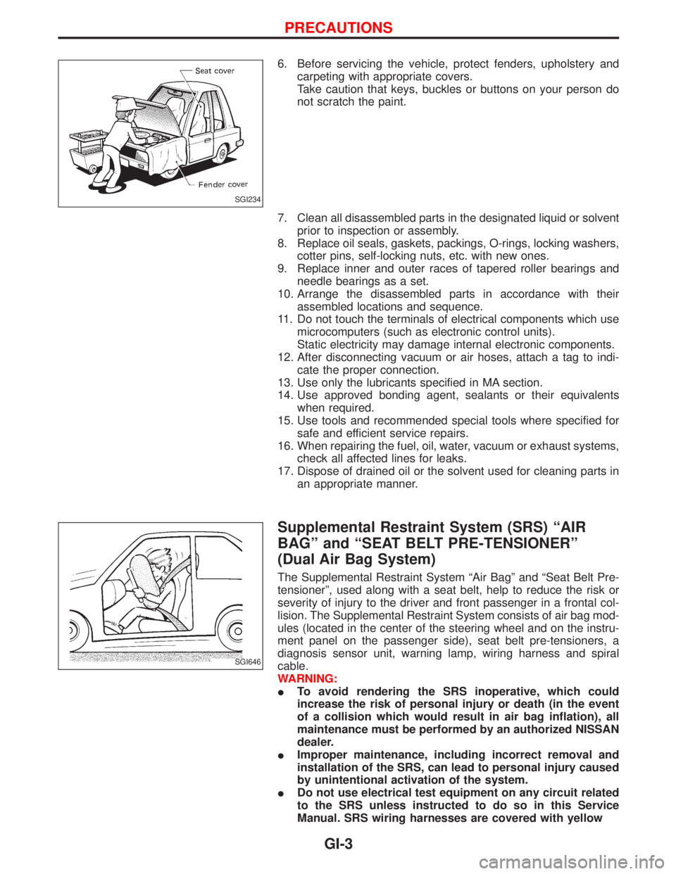
6. Before servicing the vehicle, protect fenders, upholstery and
carpeting with appropriate covers.
Take caution that keys, buckles or buttons on your person do
not scratch the paint.
7. Clean all disassembled parts in the designated liquid or solvent
prior to inspection or assembly.
8. Replace oil seals, gaskets, packings, O-rings, locking washers,
cotter pins, self-locking nuts, etc. with new ones.
9. Replace inner and outer races of tapered roller bearings and
needle bearings as a set.
10. Arrange the disassembled parts in accordance with their
assembled locations and sequence.
11. Do not touch the terminals of electrical components which use
microcomputers (such as electronic control units).
Static electricity may damage internal electronic components.
12. After disconnecting vacuum or air hoses, attach a tag to indi-
cate the proper connection.
13. Use only the lubricants specified in MA section.
14. Use approved bonding agent, sealants or their equivalents
when required.
15. Use tools and recommended special tools where specified for
safe and efficient service repairs.
16. When repairing the fuel, oil, water, vacuum or exhaust systems,
check all affected lines for leaks.
17. Dispose of drained oil or the solvent used for cleaning parts in
an appropriate manner.
Supplemental Restraint System (SRS) ªAIR
BAGº and ªSEAT BELT PRE-TENSIONERº
(Dual Air Bag System)
The Supplemental Restraint System ªAir Bagº and ªSeat Belt Pre-
tensionerº, used along with a seat belt, help to reduce the risk or
severity of injury to the driver and front passenger in a frontal col-
lision. The Supplemental Restraint System consists of air bag mod-
ules (located in the center of the steering wheel and on the instru-
ment panel on the passenger side), seat belt pre-tensioners, a
diagnosis sensor unit, warning lamp, wiring harness and spiral
cable.
WARNING:
ITo avoid rendering the SRS inoperative, which could
increase the risk of personal injury or death (in the event
of a collision which would result in air bag inflation), all
maintenance must be performed by an authorized NISSAN
dealer.
IImproper maintenance, including incorrect removal and
installation of the SRS, can lead to personal injury caused
by unintentional activation of the system.
IDo not use electrical test equipment on any circuit related
to the SRS unless instructed to do so in this Service
Manual. SRS wiring harnesses are covered with yellow
SGI234
SGI646
PRECAUTIONS
GI-3
Page 1324 of 1767
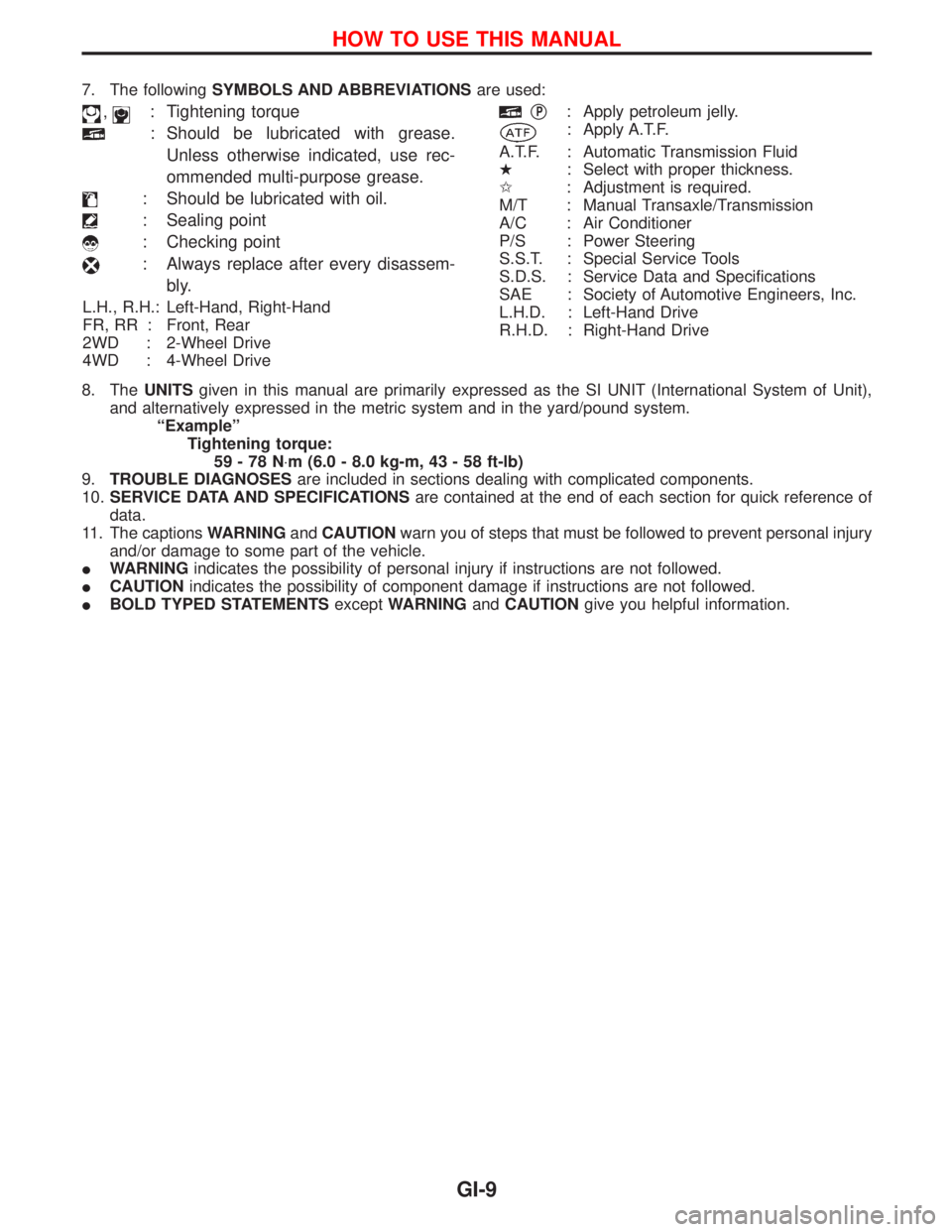
7. The followingSYMBOLS AND ABBREVIATIONSare used:
,: Tightening torque
: Should be lubricated with grease.
Unless otherwise indicated, use rec-
ommended multi-purpose grease.
: Should be lubricated with oil.
: Sealing point
: Checking point
: Always replace after every disassem-
bly.
L.H., R.H.: Left-Hand, Right-Hand
FR, RR : Front, Rear
2WD : 2-Wheel Drive
4WD : 4-Wheel Drive
qP: Apply petroleum jelly.
: Apply A.T.F.
A.T.F. : Automatic Transmission Fluid
H: Select with proper thickness.
I: Adjustment is required.
M/T : Manual Transaxle/Transmission
A/C : Air Conditioner
P/S : Power Steering
S.S.T. : Special Service Tools
S.D.S. : Service Data and Specifications
SAE : Society of Automotive Engineers, Inc.
L.H.D. : Left-Hand Drive
R.H.D. : Right-Hand Drive
8. TheUNITSgiven in this manual are primarily expressed as the SI UNIT (International System of Unit),
and alternatively expressed in the metric system and in the yard/pound system.
ªExampleº
Tightening torque:
59-78N×m (6.0 - 8.0 kg-m, 43 - 58 ft-lb)
9.TROUBLE DIAGNOSESare included in sections dealing with complicated components.
10.SERVICE DATA AND SPECIFICATIONSare contained at the end of each section for quick reference of
data.
11. The captionsWARNINGandCAUTIONwarn you of steps that must be followed to prevent personal injury
and/or damage to some part of the vehicle.
IWARNINGindicates the possibility of personal injury if instructions are not followed.
ICAUTIONindicates the possibility of component damage if instructions are not followed.
IBOLD TYPED STATEMENTSexceptWARNINGandCAUTIONgive you helpful information.
HOW TO USE THIS MANUAL
GI-9
Page 1348 of 1767
4-pole Lift
WARNING:
Do not use a 2-pole lift.
Due to weight balance of the vehicle and shape of underbody,
lift arms can not be attached in a safe way. Therefore it is rec-
ommended to use a 4-pole lift only.
Tow Truck Towing
CAUTION:
IAll applicable local laws regarding the towing operation
must be obeyed.
IIt is necessary to use proper towing equipment to avoid
possible damage to the vehicle during a towing operation.
IAttach safety chains for all towing.
IWhen towing, make sure that the transmission, steering
system and power train are in good order. If any unit is
damaged, a dolly must be used.
IWhen towing with the front wheels on the ground:
Move both the gearshift and transfer levers to neutral (ªNº
position).
Turn the ignition key to the ªOFFº position and secure the
steering wheel in a straightahead position with a rope or
similar device. Never place the ignition key in the ªLOCKº
position. This will result in damage to the steering lock
mechanism.
IWhen towing with the rear wheels on the ground, release
the parking brake and move both the gearshift and trans-
fer levers to neutral (ªNº position).
INever tow vehicle from the rear (i.e., backward) with four
wheels on the ground as this may cause serious and
expensive damage to the transmission.
LIFTING POINTS AND TOW TRUCK TOWING
GI-33
Page 1422 of 1767
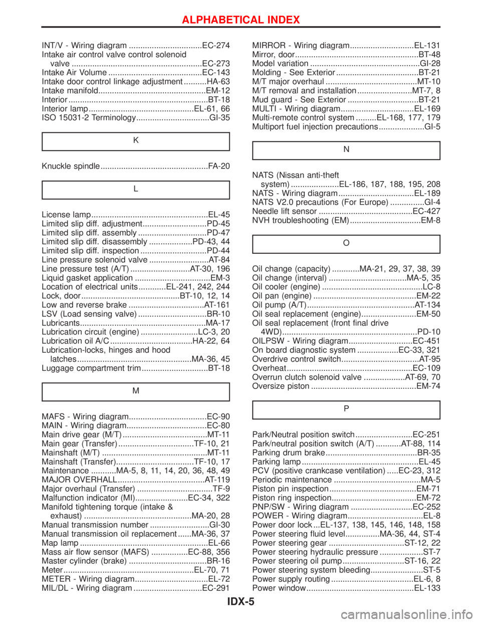
INT/V - Wiring diagram ................................EC-274
Intake air control valve control solenoid
valve .........................................................EC-273
Intake Air Volume .........................................EC-143
Intake door control linkage adjustment ..........HA-63
Intake manifold...............................................EM-12
Interior .............................................................BT-18
Interior lamp ..............................................EL-61, 66
ISO 15031-2 Terminology................................GI-35
K
Knuckle spindle ...............................................FA-20
L
License lamp ...................................................EL-45
Limited slip diff. adjustment............................PD-45
Limited slip diff. assembly ..............................PD-47
Limited slip diff. disassembly ...................PD-43, 44
Limited slip diff. inspection .............................PD-44
Line pressure solenoid valve ..........................AT-84
Line pressure test (A/T) ..........................AT-30, 196
Liquid gasket application .................................EM-3
Location of electrical units ............EL-241, 242, 244
Lock, door ...........................................BT-10, 12, 14
Low and reverse brake .................................AT-161
LSV (Load sensing valve) ..............................BR-10
Lubricants.......................................................MA-17
Lubrication circuit (engine) .........................LC-3, 20
Lubrication oil A/C ....................................HA-22, 64
Lubrication-locks, hinges and hood
latches ..................................................MA-36, 45
Luggage compartment trim .............................BT-18
M
MAFS - Wiring diagram..................................EC-90
MAIN - Wiring diagram...................................EC-80
Main drive gear (M/T) .....................................MT-11
Main gear (Transfer) .................................TF-10, 21
Mainshaft (M/T) ..............................................MT-11
Mainshaft (Transfer)..................................TF-10, 17
Maintenance ...........MA-5, 8, 11, 14, 20, 36, 48, 49
MAJOR OVERHALL ......................................AT-119
Major overhaul (Transfer) .................................TF-9
Malfunction indicator (MI).......................EC-34, 322
Manifold tightening torque (intake &
exhaust) ...............................................MA-20, 28
Manual transmission number ..........................GI-30
Manual transmission oil replacement ......MA-36, 37
Map lamp ........................................................EL-66
Mass air flow sensor (MAFS) ................EC-88, 356
Master cylinder (brake) ..................................BR-16
Meter .........................................................EL-70, 71
METER - Wiring diagram................................EL-72
MIL/DL - Wiring diagram ..............................EC-291MIRROR - Wiring diagram............................EL-131
Mirror, door......................................................BT-48
Model variation ................................................GI-28
Molding - See Exterior ....................................BT-21
M/T major overhaul ........................................MT-10
M/T removal and installation ........................MT-7, 8
Mud guard - See Exterior ...............................BT-21
MULTI - Wiring diagram................................EL-169
Multi-remote control system .........EL-168, 177, 179
Multiport fuel injection precautions ....................GI-5
N
NATS (Nissan anti-theft
system) .....................EL-186, 187, 188, 195, 208
NATS - Wiring diagram .................................EL-189
NATS V2.0 precautions (For Europe) ...............GI-4
Needle lift sensor .........................................EC-427
NVH troubleshooting (EM) ...............................EM-8
O
Oil change (capacity) ............MA-21, 29, 37, 38, 39
Oil change (interval) ..................................MA-5, 35
Oil cooler (engine) ............................................LC-8
Oil pan (engine) .............................................EM-22
Oil pump (A/T)...............................................AT-134
Oil seal replacement (engine)........................EM-50
Oil seal replacement (front final drive
4WD)...........................................................PD-10
OILPSW - Wiring diagram............................EC-451
On board diagnostic system ..................EC-33, 321
Overdrive control switch..................................AT-95
Overheat .......................................................EC-109
Overrun clutch solenoid valve ..................AT-69, 70
Oversize piston ..............................................EM-74
P
Park/Neutral position switch .........................EC-251
Park/neutral position switch (A/T) ...........AT-88, 114
Parking drum brake ........................................BR-35
Parking lamp ...................................................EL-45
PCV (positive crankcase ventilation) .....EC-23, 312
Periodic maintenance ......................................MA-5
Piston pin inspection ......................................EM-71
Piston ring inspection.....................................EM-72
PNP/SW - Wiring diagram ...........................EC-252
POWER - Wiring diagram.................................EL-8
Power door lock ...EL-137, 138, 145, 146, 148, 158
Power steering fluid level...............MA-36, 44, ST-4
Power steering gear .................................ST-12, 22
Power steering hydraulic pressure ...................ST-7
Power steering oil pump ...........................ST-16, 22
Power steering system bleeding.......................ST-5
Power supply routing ....................................EL-6, 8
Power window ...............................................EL-133
ALPHABETICAL INDEX
IDX-5
Page 1423 of 1767
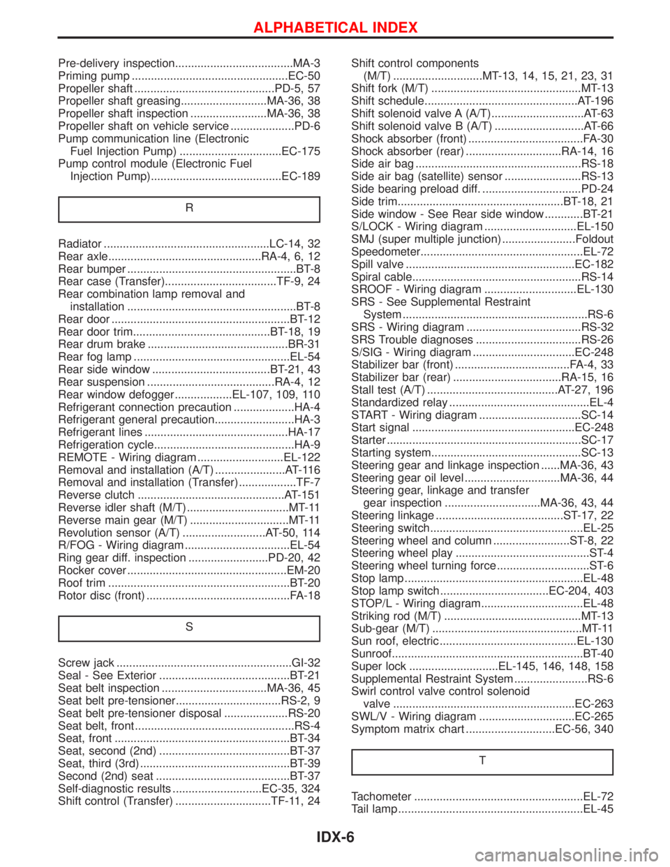
Pre-delivery inspection.....................................MA-3
Priming pump .................................................EC-50
Propeller shaft ............................................PD-5, 57
Propeller shaft greasing...........................MA-36, 38
Propeller shaft inspection ........................MA-36, 38
Propeller shaft on vehicle service ....................PD-6
Pump communication line (Electronic
Fuel Injection Pump) ................................EC-175
Pump control module (Electronic Fuel
Injection Pump).........................................EC-189
R
Radiator ....................................................LC-14, 32
Rear axle................................................RA-4, 6, 12
Rear bumper .....................................................BT-8
Rear case (Transfer)...................................TF-9, 24
Rear combination lamp removal and
installation .....................................................BT-8
Rear door ........................................................BT-12
Rear door trim...........................................BT-18, 19
Rear drum brake ............................................BR-31
Rear fog lamp .................................................EL-54
Rear side window .....................................BT-21, 43
Rear suspension ........................................RA-4, 12
Rear window defogger..................EL-107, 109, 110
Refrigerant connection precaution ...................HA-4
Refrigerant general precaution.........................HA-3
Refrigerant lines .............................................HA-17
Refrigeration cycle............................................HA-9
REMOTE - Wiring diagram ...........................EL-122
Removal and installation (A/T) ......................AT-116
Removal and installation (Transfer) ..................TF-7
Reverse clutch ..............................................AT-151
Reverse idler shaft (M/T)................................MT-11
Reverse main gear (M/T) ...............................MT-11
Revolution sensor (A/T) ..........................AT-50, 114
R/FOG - Wiring diagram .................................EL-54
Ring gear diff. inspection .........................PD-20, 42
Rocker cover ..................................................EM-20
Roof trim .........................................................BT-20
Rotor disc (front) .............................................FA-18
S
Screw jack .......................................................GI-32
Seal - See Exterior .........................................BT-21
Seat belt inspection .................................MA-36, 45
Seat belt pre-tensioner.................................RS-2, 9
Seat belt pre-tensioner disposal ....................RS-20
Seat belt, front ..................................................RS-4
Seat, front .......................................................BT-34
Seat, second (2nd) .........................................BT-37
Seat, third (3rd) ...............................................BT-39
Second (2nd) seat ..........................................BT-37
Self-diagnostic results ............................EC-35, 324
Shift control (Transfer) ..............................TF-11, 24Shift control components
(M/T) ............................MT-13, 14, 15, 21, 23, 31
Shift fork (M/T) ...............................................MT-13
Shift schedule................................................AT-196
Shift solenoid valve A (A/T).............................AT-63
Shift solenoid valve B (A/T) ............................AT-66
Shock absorber (front) ....................................FA-30
Shock absorber (rear) ..............................RA-14, 16
Side air bag ....................................................RS-18
Side air bag (satellite) sensor ........................RS-13
Side bearing preload diff. ...............................PD-24
Side trim....................................................BT-18, 21
Side window - See Rear side window ............BT-21
S/LOCK - Wiring diagram .............................EL-150
SMJ (super multiple junction) .......................Foldout
Speedometer...................................................EL-72
Spill valve .....................................................EC-182
Spiral cable.....................................................RS-14
SROOF - Wiring diagram .............................EL-130
SRS - See Supplemental Restraint
System ..........................................................RS-6
SRS - Wiring diagram ....................................RS-32
SRS Trouble diagnoses .................................RS-26
S/SIG - Wiring diagram ................................EC-248
Stabilizer bar (front) ....................................FA-4, 33
Stabilizer bar (rear) ..................................RA-15, 16
Stall test (A/T) .........................................AT-27, 196
Standardized relay ............................................EL-4
START - Wiring diagram ................................SC-14
Start signal ...................................................EC-248
Starter .............................................................SC-17
Starting system...............................................SC-13
Steering gear and linkage inspection ......MA-36, 43
Steering gear oil level ..............................MA-36, 44
Steering gear, linkage and transfer
gear inspection ..............................MA-36, 43, 44
Steering linkage ........................................ST-17, 22
Steering switch................................................EL-25
Steering wheel and column ........................ST-8, 22
Steering wheel play ..........................................ST-4
Steering wheel turning force .............................ST-6
Stop lamp ........................................................EL-48
Stop lamp switch ..................................EC-204, 403
STOP/L - Wiring diagram................................EL-48
Striking rod (M/T) ...........................................MT-13
Sub-gear (M/T) ...............................................MT-11
Sun roof, electric ...........................................EL-130
Sunroof............................................................BT-40
Super lock ............................EL-145, 146, 148, 158
Supplemental Restraint System .......................RS-6
Swirl control valve control solenoid
valve .........................................................EC-263
SWL/V - Wiring diagram ..............................EC-265
Symptom matrix chart ............................EC-56, 340
T
Tachometer .....................................................EL-72
Tail lamp ..........................................................EL-45
ALPHABETICAL INDEX
IDX-6