steering NISSAN TERRANO 2002 Service Service Manual
[x] Cancel search | Manufacturer: NISSAN, Model Year: 2002, Model line: TERRANO, Model: NISSAN TERRANO 2002Pages: 1767, PDF Size: 41.51 MB
Page 1632 of 1767
IInstall driver air bag module to steering wheel to check fit or
alignment with the wheel.
ICheck steering wheel for excessive free play.
IInstall front passenger air bag module to instrument panel to
check fit or alignment with the instrument panel.
IInstall front side air bag module to seatback to check fit and
alignment with the seat.
3) Spiral cable
ICheck spiral cable for dents, cracks, or deformities.
ICheck connectors and protective tape for damage.
ICheck steering wheel for noise, binding or heavy operation.
4) Main harness, body harness, side air bag module sub-harness
ICheck connectors for poor connections, damage, and terminals
for deformities.
ICheck harnesses for binding, chafing or cut.
5) Front seat belt pre-tensioner
ICheck harness cover and connectors for damage, terminals for
deformities, and harness for binding.
ICheck belts for damage and anchors for loose mounting.
ICheck retractor for smooth operation.
IPerform self-diagnosis for seat belt pre-tensioner using ªAIR
BAGº warning lamp or CONSULT-II.
Refer to ªSRS Operation Checkº for details. (RS-36)
6) Side air bag (satellite) sensor
ICheck side air bag (satellite) sensor (including bracket portion)
for dents, cracks or deformities.
ICheck connectors for damage, and terminals for deformities.
CAUTION:
Replace previously used special bolts and ground bolt with
new ones.
Diagnosis Sensor Unit
REMOVAL AND INSTALLATION
CAUTION:
IBefore servicing SRS, turn the ignition switch off, discon-
nect both battery cables and wait at least 3 minutes.
IThe special bolts are coated with bonding agent while the
other bolt is for ground. Do not use old bolts after removal;
replace with new ones.
ICheck diagnosis sensor unit for proper installation.
ICheck diagnosis sensor unit to ensure it is free of
deformities, dents, cracks or rust. If they show any visible
signs of damage, replace them with new ones.
ICheck diagnosis sensor unit brackets to ensure they are
free of deformities or rust.
IReplace diagnosis sensor unit if it has been dropped or
sustained an impact.
IAfter replacement of diagnosis sensor unit, perform self-
diagnosis for SRS. Refer to ªSRS Operation Checkº for
details. (RS-36)
1. Disconnect driver, front passenger and front side air bag mod-
ule connectors. Also, disconnect front seat belt pre-tensioner
connector.
2. Remove console box. Refer to BT-22, ªINSTRUMENT PANEL
ASSEMBLYº.
3. Disconnect diagnosis sensor unit connector.
4. Remove ground bolt and also remove special bolts using the
TAMPER RESISTANT TORX (Size T50), from diagnosis sen-
sor unit.
Then remove the diagnosis sensor unit.
SUPPLEMENTAL RESTRAINT SYSTEM (SRS)
Maintenance Items (Cont'd)
RS-11
Page 1635 of 1767
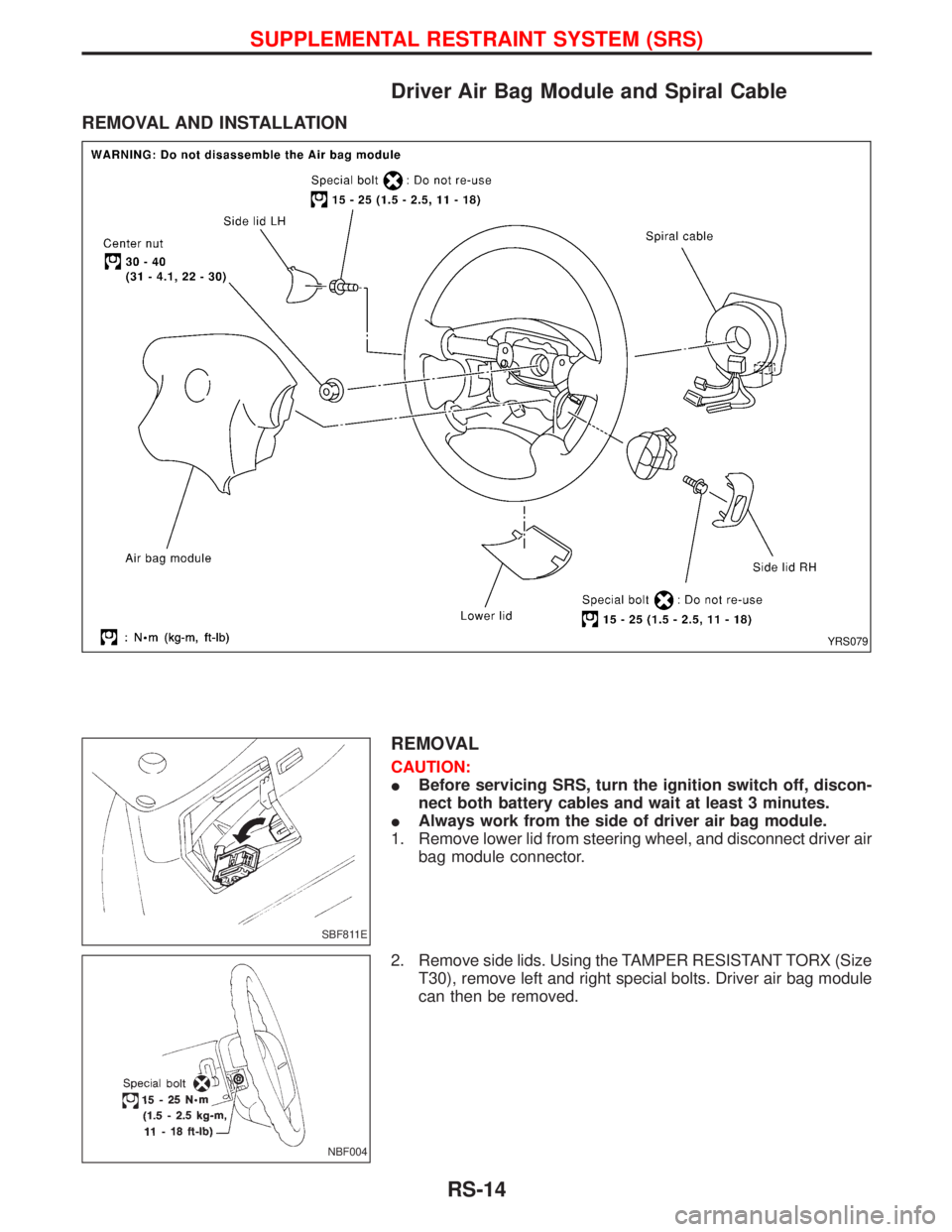
Driver Air Bag Module and Spiral Cable
REMOVAL AND INSTALLATION
REMOVAL
CAUTION:
IBefore servicing SRS, turn the ignition switch off, discon-
nect both battery cables and wait at least 3 minutes.
IAlways work from the side of driver air bag module.
1. Remove lower lid from steering wheel, and disconnect driver air
bag module connector.
2. Remove side lids. Using the TAMPER RESISTANT TORX (Size
T30), remove left and right special bolts. Driver air bag module
can then be removed.
YRS079
SBF811E
NBF004
SUPPLEMENTAL RESTRAINT SYSTEM (SRS)
RS-14
Page 1636 of 1767
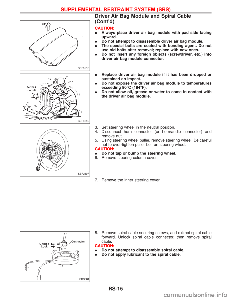
CAUTION:
IAlways place driver air bag module with pad side facing
upward.
IDo not attempt to disassemble driver air bag module.
IThe special bolts are coated with bonding agent. Do not
use old bolts after removal; replace with new ones.
IDo not insert any foreign objects (screwdriver, etc.) into
driver air bag module connector.
IReplace driver air bag module if it has been dropped or
sustained an impact.
IDo not expose the driver air bag module to temperatures
exceeding 90ÉC (194ÉF).
IDo not allow oil, grease or water to come in contact with
the driver air bag module.
3. Set steering wheel in the neutral position.
4. Disconnect horn connector (or horn/audio connector) and
remove nut.
5. Using steering wheel puller, remove steering wheel. Be careful
not to over-tighten puller bolt on steering wheel.
CAUTION:
IDo not tap or bump the steering wheel.
6. Remove steering column cover.
7. Remove the inner steering cover.
8. Remove spiral cable securing screws, and extract spiral cable
forward. Unlock spiral cable connector, then remove spiral
cable.
CAUTION:
IDo not attempt to disassemble spiral cable.
IDo not apply lubricant to the spiral cable.
SBF813E
SBF814E
SBF239F
SRS384
SUPPLEMENTAL RESTRAINT SYSTEM (SRS)
Driver Air Bag Module and Spiral Cable
(Cont'd)
RS-15
Page 1637 of 1767
INSTALLATION
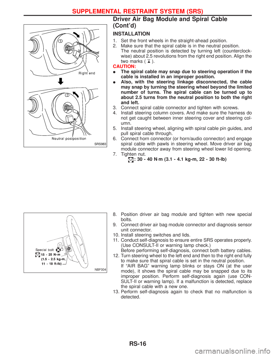
1. Set the front wheels in the straight-ahead position.
2. Make sure that the spiral cable is in the neutral position.
The neutral position is detected by turning left (counterclock-
wise) about 2.5 revolutions from the right end position. Align the
two marks (
).
CAUTION:
IThe spiral cable may snap due to steering operation if the
cable is installed in an improper position.
IAlso, with the steering linkage disconnected, the cable
may snap by turning the steering wheel beyond the limited
number of turns. The spiral cable can be turned up to
about 2.5 turns from the neutral position to both the right
and left.
3. Connect spiral cable connector and tighten with screws.
4. Install steering column covers. And make sure the harness do
not get caught between inner steering cover and steering col-
umn.
5. Install steering wheel, aligning with spiral cable pin guides, and
pull spiral cable through.
6. Connect horn connector (or horn/audio connector) and engage
spiral cable with pawls in steering wheel. Move driver air bag
module connector away from steering wheel lower lid opening.
7. Tighten nut.
:30-40N×m (3.1 - 4.1 kg-m, 22 - 30 ft-lb)
8. Position driver air bag module and tighten with new special
bolts.
9. Connect driver air bag module connector and diagnosis sensor
unit connector.
10. Install steering switches and lids.
11. Conduct self-diagnosis to ensure entire SRS operates properly.
(Use CONSULT-II or warning lamp check.)
Before performing self-diagnosis, connect both battery cables.
12. Turn steering wheel to the left end and then to the right end fully
to make sure that spiral cable is set in the neutral position.
If ªAIR BAGº warning lamp blinks or stays ON (at the user
mode), it shows the spiral cable may be snapped due to its
improper position. Perform self-diagnosis again (use CON-
SULT-II or warning lamp). If a malfunction is detected, replace
the spiral cable with a new one.
13. Perform self-diagnosis again to check that no malfunction is
detected.
SRS983
NBF004
SUPPLEMENTAL RESTRAINT SYSTEM (SRS)
Driver Air Bag Module and Spiral Cable
(Cont'd)
RS-16
Page 1639 of 1767
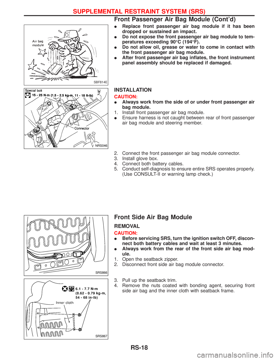
IReplace front passenger air bag module if it has been
dropped or sustained an impact.
IDo not expose the front passenger air bag module to tem-
peratures exceeding 90ÉC (194ÉF).
IDo not allow oil, grease or water to come in contact with
the front passenger air bag module.
IAfter front passenger air bag inflates, the front instrument
panel assembly should be replaced if damaged.
INSTALLATION
CAUTION:
IAlways work from the side of or under front passenger air
bag module.
1. Install front passenger air bag module.
IEnsure harness is not caught between rear of front passenger
air bag module and steering member.
2. Connect the front passenger air bag module connector.
3. Install glove box.
4. Connect both battery cables.
5. Conduct self-diagnosis to ensure entire SRS operates properly.
(Use CONSULT-II or warning lamp check.)
Front Side Air Bag Module
REMOVAL
CAUTION:
IBefore servicing SRS, turn the ignition switch OFF, discon-
nect both battery cables and wait at least 3 minutes.
IAlways work from the rear of the front side air bag mod-
ule.
1. Open the seatback zipper.
2. Disconnect front side air bag module connector.
3. Pull up the seatback trim.
4. Remove the nuts coated with bonding agent, securing front
side air bag and the inner cloth with seatback frame.
SBF814E
NRS046
SRS866
SRS867
SUPPLEMENTAL RESTRAINT SYSTEM (SRS)
Front Passenger Air Bag Module (Cont'd)
RS-18
Page 1678 of 1767
Collision Diagnosis
FOR FRONTAL COLLISION
To repair the SRS, perform the following steps.
When SRS (except the side air bag modules) is activated in a collision:
1) Replace the diagnosis sensor unit.
2) Remove the air bag modules (except the side air bag modules) and front seat belt pre-tensioner assem-
blies.
3) Check the SRS components using the table shown below:
IReplace any SRS components showing visible signs of damage (dents, cracks and deformation).
4) Install new air bag modules (except the side air bag module) and front seat belt pre-tensioner assemblies.
5) Conduct self-diagnosis using CONSULT-II or ªAIR BAGº warning lamp. Refer to ªSRS Operation Checkº
for details (RS-36). Ensure entire SRS operation properly.
When SRS is not activated in a collision:
1) Check the SRS components using the table shown below:
IReplace any SRS components showing visible signs of damage (dents, cracks and deformation).
2) Conduct self-diagnosis using CONSULT-II or ªAIR BAGº warning lamp. Refer to ªSRS Operation Checkº
for details (RS-36). Ensure entire SRS operation properly.
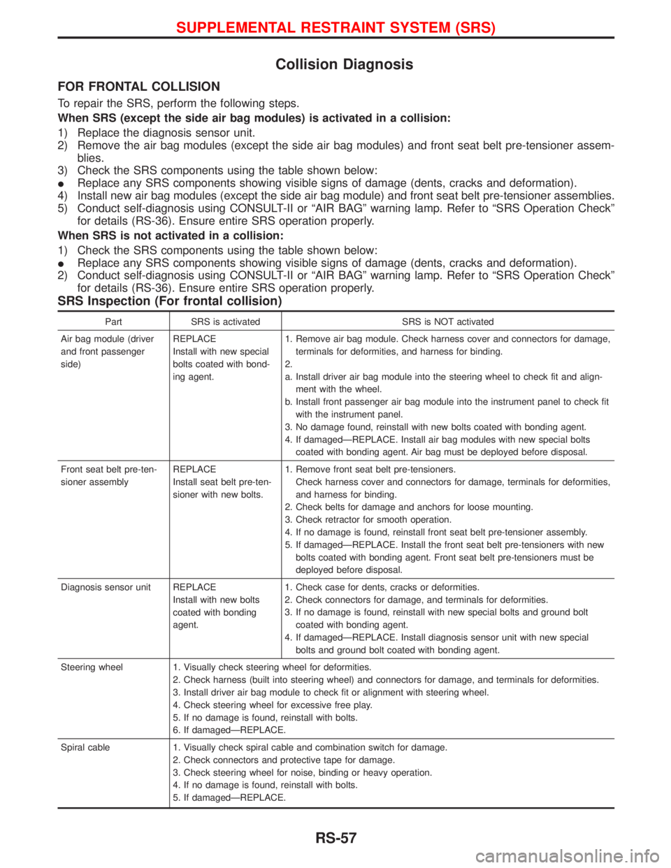
SRS Inspection (For frontal collision)
Part SRS is activated SRS is NOT activated
Air bag module (driver
and front passenger
side)REPLACE
Install with new special
bolts coated with bond-
ing agent.1. Remove air bag module. Check harness cover and connectors for damage,
terminals for deformities, and harness for binding.
2.
a. Install driver air bag module into the steering wheel to check fit and align-
ment with the wheel.
b. Install front passenger air bag module into the instrument panel to check fit
with the instrument panel.
3. No damage found, reinstall with new bolts coated with bonding agent.
4. If damagedÐREPLACE. Install air bag modules with new special bolts
coated with bonding agent. Air bag must be deployed before disposal.
Front seat belt pre-ten-
sioner assemblyREPLACE
Install seat belt pre-ten-
sioner with new bolts.1. Remove front seat belt pre-tensioners.
Check harness cover and connectors for damage, terminals for deformities,
and harness for binding.
2. Check belts for damage and anchors for loose mounting.
3. Check retractor for smooth operation.
4. If no damage is found, reinstall front seat belt pre-tensioner assembly.
5. If damagedÐREPLACE. Install the front seat belt pre-tensioners with new
bolts coated with bonding agent. Front seat belt pre-tensioners must be
deployed before disposal.
Diagnosis sensor unit REPLACE
Install with new bolts
coated with bonding
agent.1. Check case for dents, cracks or deformities.
2. Check connectors for damage, and terminals for deformities.
3. If no damage is found, reinstall with new special bolts and ground bolt
coated with bonding agent.
4. If damagedÐREPLACE. Install diagnosis sensor unit with new special
bolts and ground bolt coated with bonding agent.
Steering wheel 1. Visually check steering wheel for deformities.
2. Check harness (built into steering wheel) and connectors for damage, and terminals for deformities.
3. Install driver air bag module to check fit or alignment with steering wheel.
4. Check steering wheel for excessive free play.
5. If no damage is found, reinstall with bolts.
6. If damagedÐREPLACE.
Spiral cable 1. Visually check spiral cable and combination switch for damage.
2. Check connectors and protective tape for damage.
3. Check steering wheel for noise, binding or heavy operation.
4. If no damage is found, reinstall with bolts.
5. If damagedÐREPLACE.
SUPPLEMENTAL RESTRAINT SYSTEM (SRS)
RS-57
Page 1712 of 1767
STEERING SYSTEM
SECTION
ST
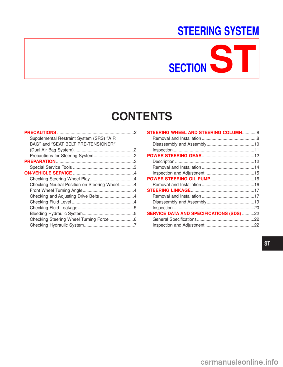
CONTENTS
PRECAUTIONS...............................................................2
Supplemental Restraint System (SRS)²AIR
BAG²and²SEAT BELT PRE-TENSIONER²
(Dual Air Bag System) .................................................2
Precautions for Steering System .................................2
PREPARATION................................................................3
Special Service Tools ..................................................3
ON-VEHICLE SERVICE..................................................4
Checking Steering Wheel Play ....................................4
Checking Neutral Position on Steering Wheel ............4
Front Wheel Turning Angle ..........................................4
Checking and Adjusting Drive Belts ............................4
Checking Fluid Level ...................................................4
Checking Fluid Leakage ..............................................5
Bleeding Hydraulic System..........................................5
Checking Steering Wheel Turning Force ....................6
Checking Hydraulic System.........................................7STEERING WHEEL AND STEERING COLUMN............8
Removal and Installation .............................................8
Disassembly and Assembly .......................................10
Inspection................................................................... 11
POWER STEERING GEAR...........................................12
Description .................................................................12
Removal and Installation ...........................................14
Inspection and Adjustment ........................................15
POWER STEERING OIL PUMP....................................16
Removal and Installation ...........................................16
STEERING LINKAGE....................................................17
Removal and Installation ...........................................17
Disassembly and Assembly .......................................19
Inspection...................................................................20
SERVICE DATA AND SPECIFICATIONS (SDS)..........22
General Specifications ...............................................22
Inspection and Adjustment ........................................22
Page 1713 of 1767
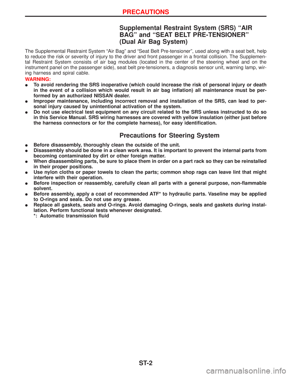
Supplemental Restraint System (SRS) ªAIR
BAGº and ªSEAT BELT PRE-TENSIONERº
(Dual Air Bag System)
The Supplemental Restraint System ªAir Bagº and ªSeat Belt Pre-tensionerº, used along with a seat belt, help
to reduce the risk or severity of injury to the driver and front passenger in a frontal collision. The Supplemen-
tal Restraint System consists of air bag modules (located in the center of the steering wheel and on the
instrument panel on the passenger side), seat belt pre-tensioners, a diagnosis sensor unit, warning lamp, wir-
ing harness and spiral cable.
WARNING:
ITo avoid rendering the SRS inoperative (which could increase the risk of personal injury or death
in the event of a collision which would result in air bag inflation) all maintenance must be per-
formed by an authorized NISSAN dealer.
IImproper maintenance, including incorrect removal and installation of the SRS, can lead to per-
sonal injury caused by unintentional activation of the system.
IDo not use electrical test equipment on any circuit related to the SRS unless instructed to do so
in this Service Manual. SRS wiring harnesses are covered with yellow insulation (either just before
the harness connectors or for the complete harness), for easy identification.
Precautions for Steering System
IBefore disassembly, thoroughly clean the outside of the unit.
IDisassembly should be done in a clean work area. It is important to prevent the internal parts from
becoming contaminated by dirt or other foreign matter.
IWhen disassembling parts, be sure to place them in order on a part rack so they can be reinstalled
in their proper positions.
IUse nylon cloths or paper towels to clean the parts; common shop rags can leave lint that might
interfere with their operation.
IBefore inspection or reassembly, carefully clean all parts with a general purpose, non-flammable
solvent.
IBefore assembly, apply a coat of recommended ATF* to hydraulic parts. Vaseline may be applied
to O-rings and seals. Do not use any grease.
IReplace all gaskets, seals and O-rings. Avoid damaging O-rings, seals and gaskets during instal-
lation. Perform functional tests whenever designated.
*: Automatic transmission fluid
PRECAUTIONS
ST-2
Page 1714 of 1767
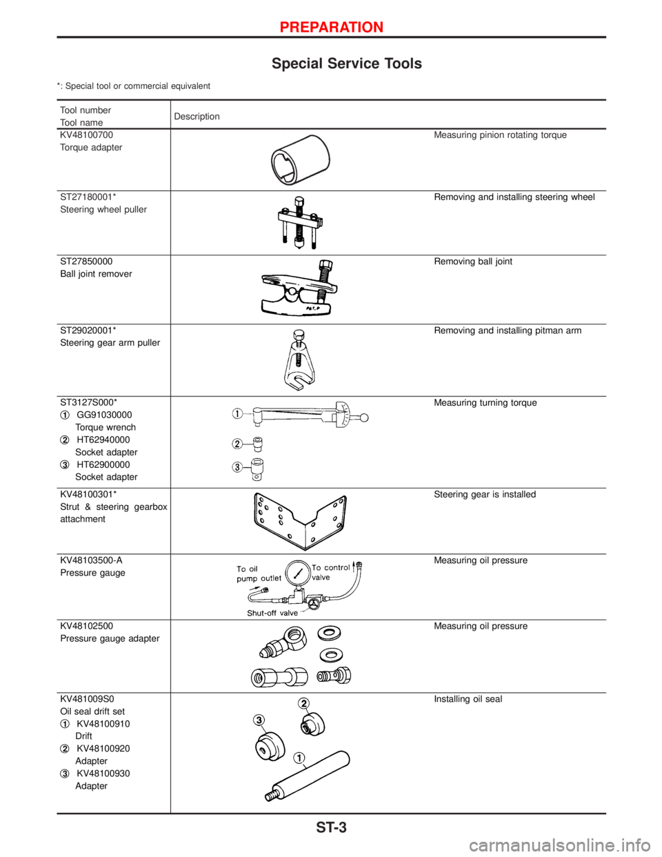
Special Service Tools
*: Special tool or commercial equivalent
Tool number
Tool nameDescription
KV48100700
Torque adapter
Measuring pinion rotating torque
ST27180001*
Steering wheel puller
Removing and installing steering wheel
ST27850000
Ball joint remover
Removing ball joint
ST29020001*
Steering gear arm puller
Removing and installing pitman arm
ST3127S000*
q
1GG91030000
Torque wrench
q
2HT62940000
Socket adapter
q
3HT62900000
Socket adapter
Measuring turning torque
KV48100301*
Strut & steering gearbox
attachment
Steering gear is installed
KV48103500-A
Pressure gauge
Measuring oil pressure
KV48102500
Pressure gauge adapter
Measuring oil pressure
KV481009S0
Oil seal drift set
q
1KV48100910
Drift
q
2KV48100920
Adapter
q
3KV48100930
Adapter
Installing oil seal
PREPARATION
ST-3
Page 1715 of 1767
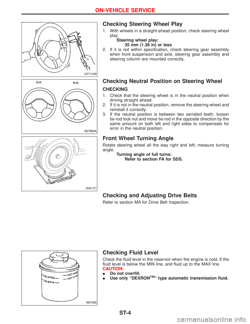
Checking Steering Wheel Play
1. With wheels in a straight-ahead position, check steering wheel
play.
Steering wheel play:
35 mm (1.38 in) or less
2. If it is not within specification, check steering gear assembly
when front suspension and axle, steering gear assembly and
steering column are mounted correctly.
Checking Neutral Position on Steering Wheel
CHECKING
1. Check that the steering wheel is in the neutral position when
driving straight ahead.
2. If it is not in the neutral position, remove the steering wheel and
reinstall it correctly.
3. If the neutral position is between two serrated teeth, loosen
tie-rod lock nut and move tie-rod in the opposite direction by the
same amount on both left and right sides to compensate for
error in the neutral position.
Front Wheel Turning Angle
Rotate steering wheel all the way right and left; measure turning
angle.
Turning angle of full turns:
Refer to section FA for SDS.
Checking and Adjusting Drive Belts
Refer to section MA for Drive Belt Inspection.
Checking Fluid Level
Check the fluid level in the reservoir when the engine is cold. If the
fluid level is below the MIN line, and fluid up to the MAX line.
CAUTION:
IDo not overfill.
IUse only ªDEXRON
TMº type automatic transmission fluid.
SST103B
SST900A
SMA127
NST030
ON-VEHICLE SERVICE
ST-4