Ignition pump wiring NISSAN TERRANO 2002 Service Repair Manual
[x] Cancel search | Manufacturer: NISSAN, Model Year: 2002, Model line: TERRANO, Model: NISSAN TERRANO 2002Pages: 1767, PDF Size: 41.51 MB
Page 490 of 1767
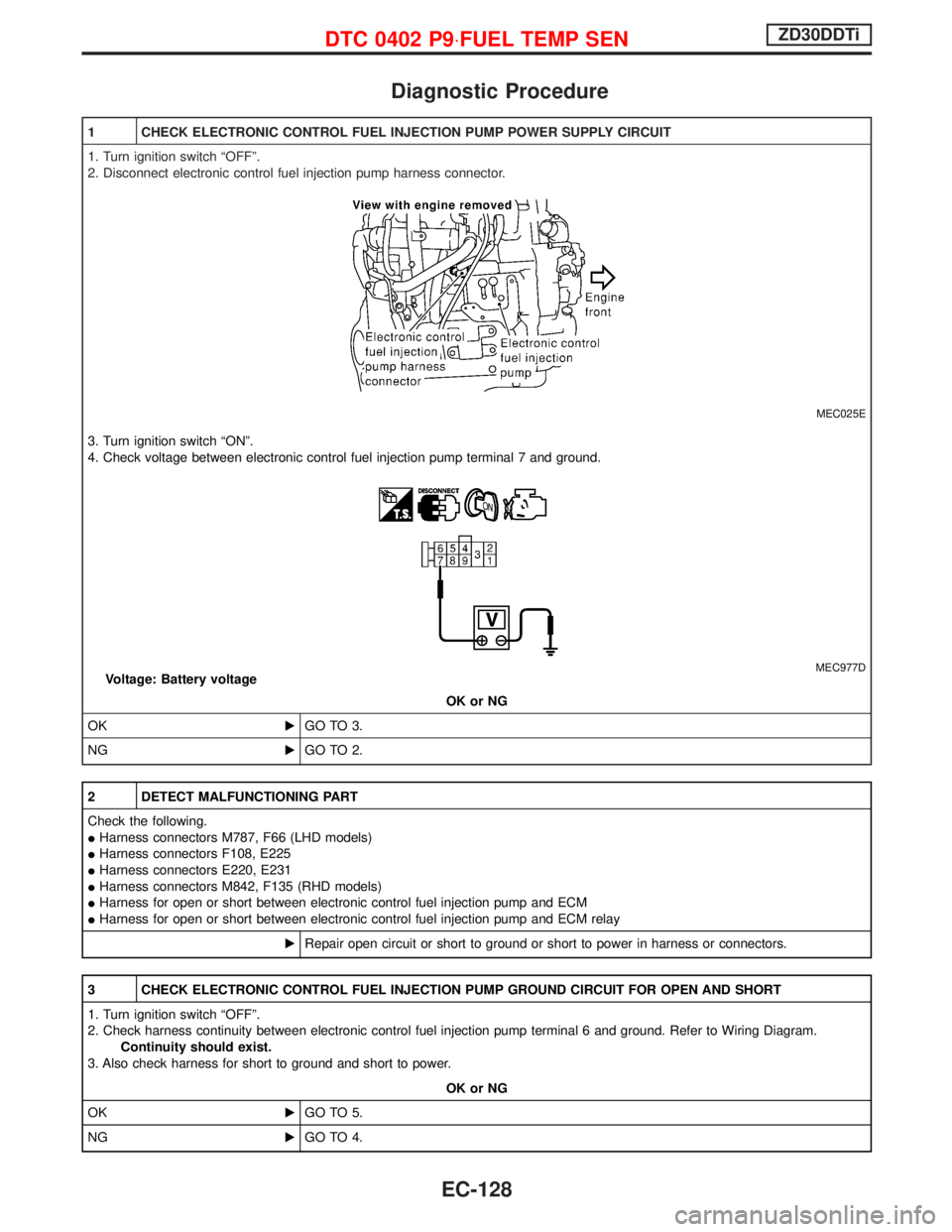
Diagnostic Procedure
1 CHECK ELECTRONIC CONTROL FUEL INJECTION PUMP POWER SUPPLY CIRCUIT
1. Turn ignition switch ªOFFº.
2. Disconnect electronic control fuel injection pump harness connector.
MEC025E
3. Turn ignition switch ªONº.
4. Check voltage between electronic control fuel injection pump terminal 7 and ground.
MEC977DVoltage: Battery voltage
OK or NG
OKEGO TO 3.
NGEGO TO 2.
2 DETECT MALFUNCTIONING PART
Check the following.
IHarness connectors M787, F66 (LHD models)
IHarness connectors F108, E225
IHarness connectors E220, E231
IHarness connectors M842, F135 (RHD models)
IHarness for open or short between electronic control fuel injection pump and ECM
IHarness for open or short between electronic control fuel injection pump and ECM relay
ERepair open circuit or short to ground or short to power in harness or connectors.
3 CHECK ELECTRONIC CONTROL FUEL INJECTION PUMP GROUND CIRCUIT FOR OPEN AND SHORT
1. Turn ignition switch ªOFFº.
2. Check harness continuity between electronic control fuel injection pump terminal 6 and ground. Refer to Wiring Diagram.
Continuity should exist.
3. Also check harness for short to ground and short to power.
OK or NG
OKEGO TO 5.
NGEGO TO 4.
DTC 0402 P9×FUEL TEMP SENZD30DDTi
EC-128
Page 528 of 1767

Diagnostic Procedure
1 CHECK ELECTRONIC CONTROL FUEL INJECTION PUMP POWER SUPPLY CIRCUIT
1. Turn ignition switch ªOFFº.
2. Disconnect electronic control fuel injection pump harness connector.
MEC025E
3. Turn ignition switch ªONº.
4. Check voltage between electronic control fuel injection pump terminal 7 and ground.
MEC977DVoltage: Battery voltage
OK or NG
OKEGO TO 3.
NGEGO TO 2.
2 DETECT MALFUNCTIONING PART
Check the following.
IHarness connectors M787, F66
IHarness connectors F108, E225
IHarness connectors E220, E231
IHarness connectors M842, F135 (RHD models)
IHarness for open or short between electronic control fuel injection pump and ECM
IHarness for open or short between electronic control fuel injection pump and ECM relay
ERepair open circuit or short to ground or short to power in harness or connectors.
3 CHECK ELECTRONIC CONTROL FUEL INJECTION PUMP GROUND CIRCUIT FOR OPEN AND SHORT
1. Turn ignition switch ªOFFº.
2. Check harness continuity between electronic control fuel injection pump terminal 6 and ground. Refer to Wiring Diagram.
Continuity should exist.
3. Also check harness for short to ground and short to power.
OK or NG
OKEGO TO 5.
NGEGO TO 4.
DTC 0701 P1×CAM POS SENZD30DDTi
EC-166
Page 535 of 1767
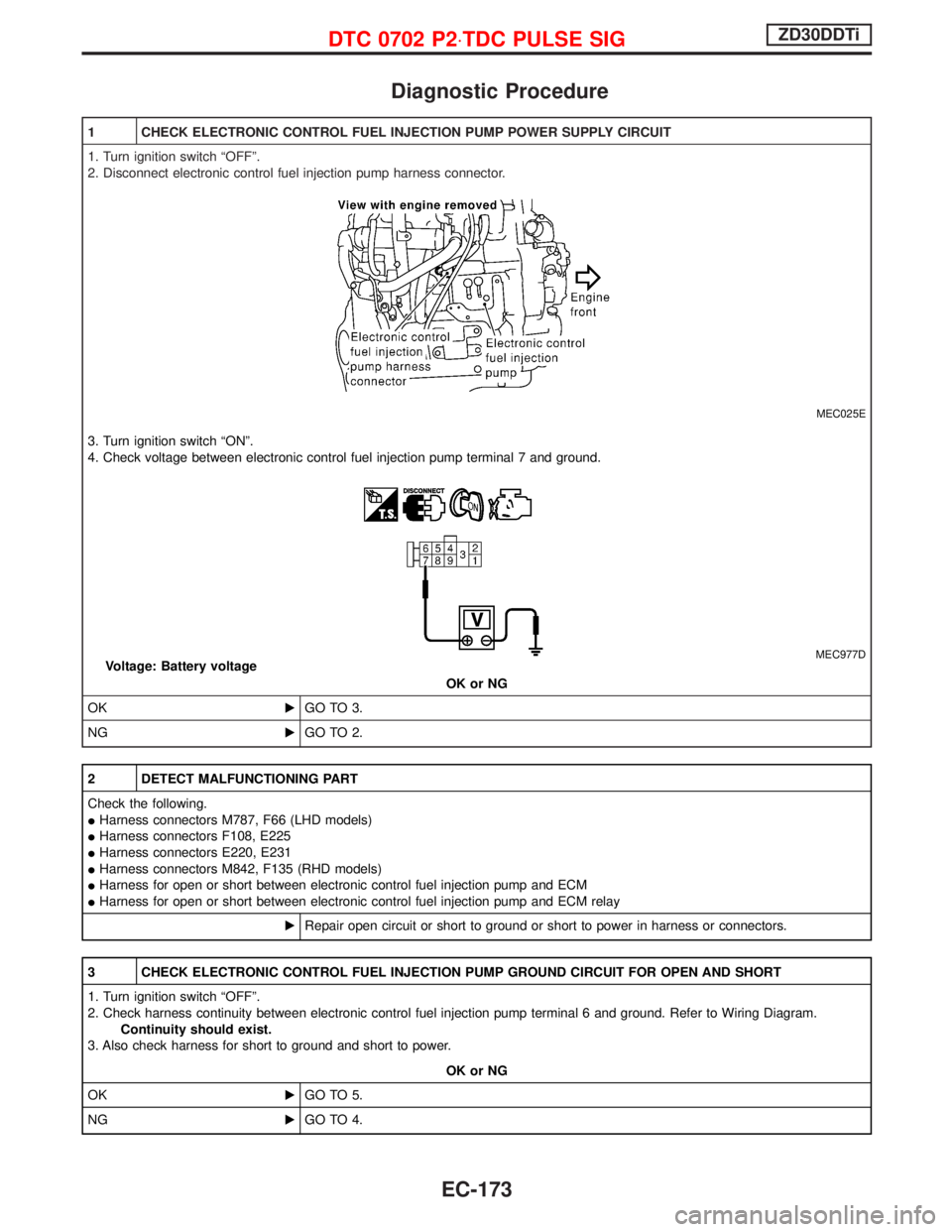
Diagnostic Procedure
1 CHECK ELECTRONIC CONTROL FUEL INJECTION PUMP POWER SUPPLY CIRCUIT
1. Turn ignition switch ªOFFº.
2. Disconnect electronic control fuel injection pump harness connector.
MEC025E
3. Turn ignition switch ªONº.
4. Check voltage between electronic control fuel injection pump terminal 7 and ground.
MEC977DVoltage: Battery voltage
OK or NG
OKEGO TO 3.
NGEGO TO 2.
2 DETECT MALFUNCTIONING PART
Check the following.
IHarness connectors M787, F66 (LHD models)
IHarness connectors F108, E225
IHarness connectors E220, E231
IHarness connectors M842, F135 (RHD models)
IHarness for open or short between electronic control fuel injection pump and ECM
IHarness for open or short between electronic control fuel injection pump and ECM relay
ERepair open circuit or short to ground or short to power in harness or connectors.
3 CHECK ELECTRONIC CONTROL FUEL INJECTION PUMP GROUND CIRCUIT FOR OPEN AND SHORT
1. Turn ignition switch ªOFFº.
2. Check harness continuity between electronic control fuel injection pump terminal 6 and ground. Refer to Wiring Diagram.
Continuity should exist.
3. Also check harness for short to ground and short to power.
OK or NG
OKEGO TO 5.
NGEGO TO 4.
DTC 0702 P2×TDC PULSE SIGZD30DDTi
EC-173
Page 542 of 1767
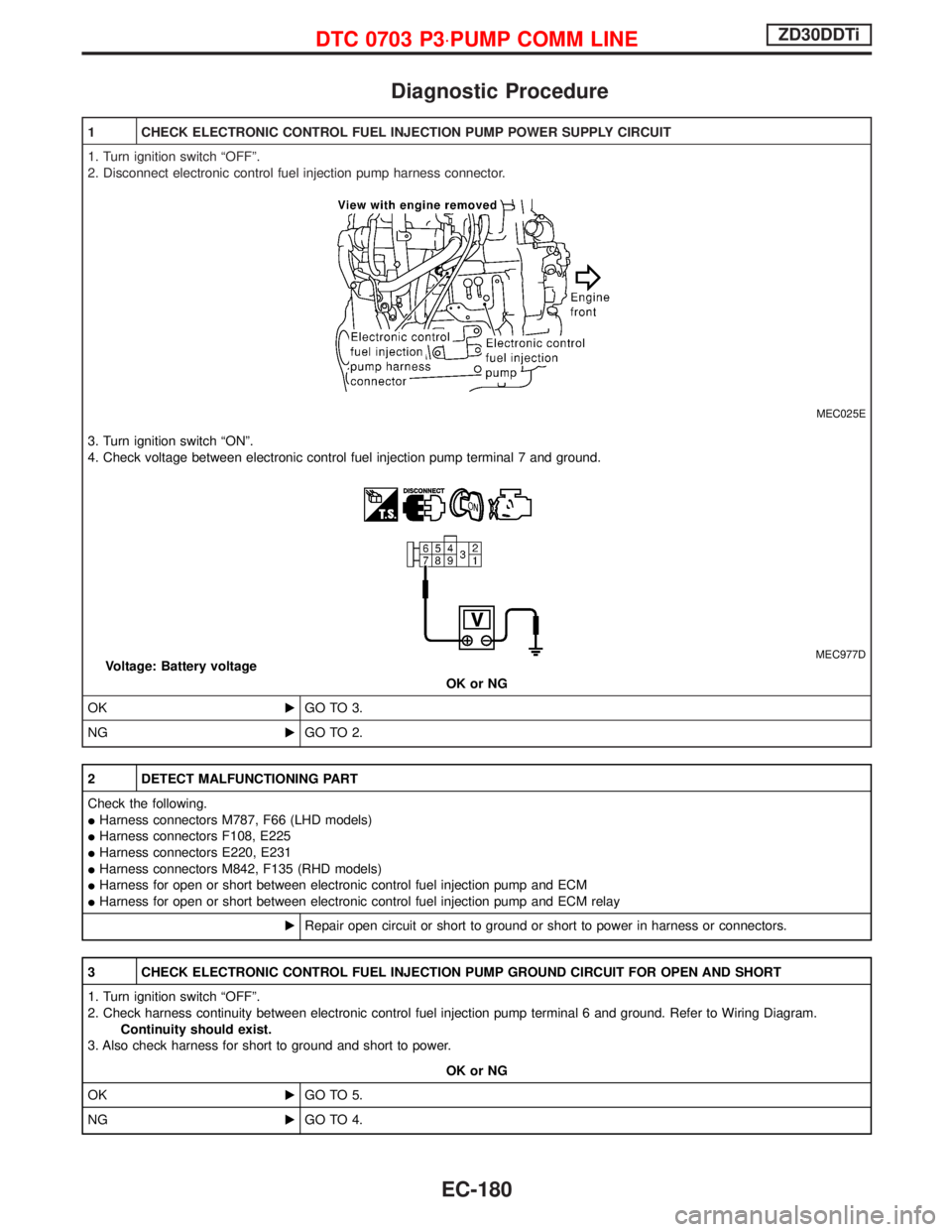
Diagnostic Procedure
1 CHECK ELECTRONIC CONTROL FUEL INJECTION PUMP POWER SUPPLY CIRCUIT
1. Turn ignition switch ªOFFº.
2. Disconnect electronic control fuel injection pump harness connector.
MEC025E
3. Turn ignition switch ªONº.
4. Check voltage between electronic control fuel injection pump terminal 7 and ground.
MEC977DVoltage: Battery voltage
OK or NG
OKEGO TO 3.
NGEGO TO 2.
2 DETECT MALFUNCTIONING PART
Check the following.
IHarness connectors M787, F66 (LHD models)
IHarness connectors F108, E225
IHarness connectors E220, E231
IHarness connectors M842, F135 (RHD models)
IHarness for open or short between electronic control fuel injection pump and ECM
IHarness for open or short between electronic control fuel injection pump and ECM relay
ERepair open circuit or short to ground or short to power in harness or connectors.
3 CHECK ELECTRONIC CONTROL FUEL INJECTION PUMP GROUND CIRCUIT FOR OPEN AND SHORT
1. Turn ignition switch ªOFFº.
2. Check harness continuity between electronic control fuel injection pump terminal 6 and ground. Refer to Wiring Diagram.
Continuity should exist.
3. Also check harness for short to ground and short to power.
OK or NG
OKEGO TO 5.
NGEGO TO 4.
DTC 0703 P3×PUMP COMM LINEZD30DDTi
EC-180
Page 549 of 1767
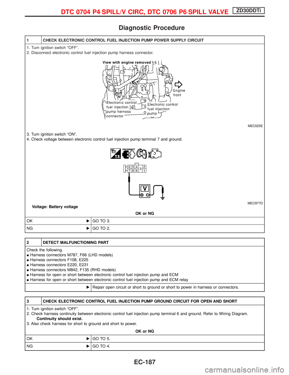
Diagnostic Procedure
1 CHECK ELECTRONIC CONTROL FUEL INJECTION PUMP POWER SUPPLY CIRCUIT
1. Turn ignition switch ªOFFº.
2. Disconnect electronic control fuel injection pump harness connector.
MEC025E
3. Turn ignition switch ªONº.
4. Check voltage between electronic control fuel injection pump terminal 7 and ground.
MEC977DVoltage: Battery voltage
OK or NG
OKEGO TO 3.
NGEGO TO 2.
2 DETECT MALFUNCTIONING PART
Check the following.
IHarness connectors M787, F66 (LHD models)
IHarness connectors F108, E225
IHarness connectors E220, E231
IHarness connectors M842, F135 (RHD models)
IHarness for open or short between electronic control fuel injection pump and ECM
IHarness for open or short between electronic control fuel injection pump and ECM relay
ERepair open circuit or short to ground or short to power in harness or connectors.
3 CHECK ELECTRONIC CONTROL FUEL INJECTION PUMP GROUND CIRCUIT FOR OPEN AND SHORT
1. Turn ignition switch ªOFFº.
2. Check harness continuity between electronic control fuel injection pump terminal 6 and ground. Refer to Wiring Diagram.
Continuity should exist.
3. Also check harness for short to ground and short to power.
OK or NG
OKEGO TO 5.
NGEGO TO 4.
DTC 0704 P4×SPILL/V CIRC, DTC 0706 P6×SPILL VALVEZD30DDTi
EC-187
Page 560 of 1767

4 DETECT MALFUNCTIONING PART
Check the following.
IHarness connectors M787, F66 (LHD models)
IHarness connectors F108, E225
IHarness connectors E220, E231
IHarness connectors M842, F135 (RHD models)
IHarness for open or short between electronic control fuel injection pump and ECM
IHarness for open or short between electronic control fuel injection pump and ECM relay
ERepair open circuit or short to ground or short to power in harness or connectors.
5 CHECK ELECTRONIC CONTROL FUEL INJECTION PUMP GROUND CIRCUIT FOR OPEN AND SHORT
1. Turn ignition switch ªOFFº.
2. Check harness continuity between electronic control fuel injection pump terminal 6 and ground. Refer to Wiring Diagram.
Continuity should exist.
3. Also check harness for short to ground and short to power.
OK or NG
OKEGO TO 7.
NGEGO TO 6.
6 DETECT MALFUNCTIONING PART
Check the following.
IHarness connectors E231, E220
IHarness for open or short between electronic control fuel injection pump and engine ground
ERepair open circuit or short to ground or short to power in harness or connectors.
7 CHECK COMMUNICATION LINE FOR OPEN AND SHORT
1. Check continuity between the following terminals. Refer to Wiring Diagram.
MTBL0444
Continuity should exist.
2. Also check harness for short to ground and short to power.
OK or NG
OKEGO TO 9.
NGEGO TO 8.
8 DETECT MALFUNCTIONING PART
Check the following.
IHarness connectors E231, E220
IHarness connectors E227, F106
IHarness connectors F135, M842 (RHD models)
IHarness for open or short between electronic control fuel injection pump and ECM
ERepair open circuit or short to ground or short to power in harness or connectors.
DTC 0707 P7×F/INJ TIMG FBZD30DDTi
Diagnostic Procedure (Cont'd)
EC-198
Page 582 of 1767
4 DETECT MALFUNCTIONING PART
Check the following.
IHarness connectors E225, F108
IHarness connectors F135, M852 (RHD models)
IHarness for open or short between ECM and charge air pressure sensor
ERepair open circuit or short to ground or short to power in harness or connectors.
5 CHECK CHARGE AIR PRESSURE SENSOR INPUT SIGNAL CIRCUIT FOR OPEN AND SHORT
1. Disconnect ECM harness connector.
2. Check harness continuity between ECM terminal 46 and charge air pressure sensor terminal 2. Refer to Wiring Diagram.
Continuity should exist.
3. Also check harness for short to ground and short to power.
OK or NG
OKEGO TO 7.
NGEGO TO 6.
6 DETECT MALFUNCTIONING PART
Check the following.
IHarness connectors E225, F108
IHarness connectors F135, M842 (RHD models)
IHarness for open or short between charge air pressure sensor and ECM
ERepair open circuit or short to ground or short to power in harness or connectors.
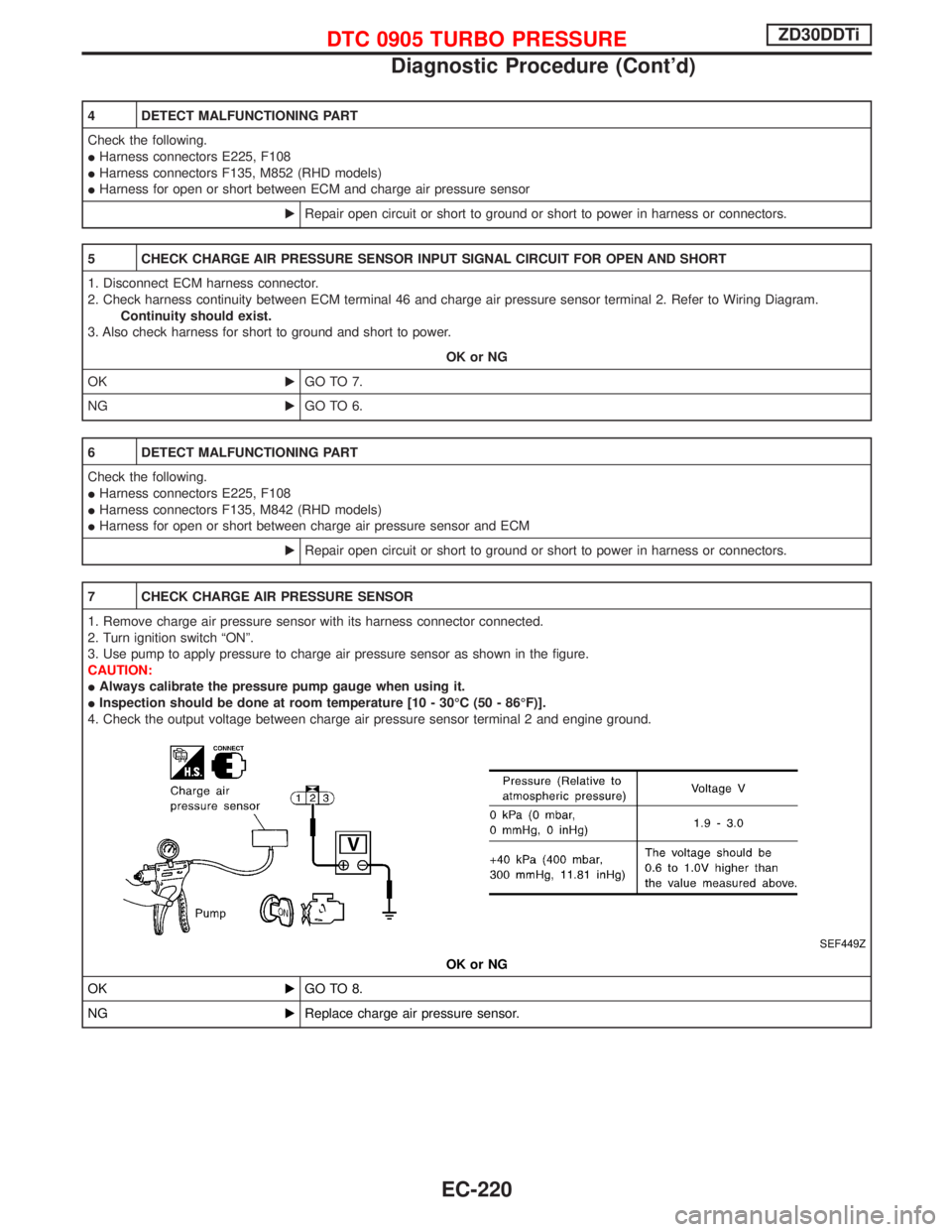
7 CHECK CHARGE AIR PRESSURE SENSOR
1. Remove charge air pressure sensor with its harness connector connected.
2. Turn ignition switch ªONº.
3. Use pump to apply pressure to charge air pressure sensor as shown in the figure.
CAUTION:
IAlways calibrate the pressure pump gauge when using it.
IInspection should be done at room temperature [10 - 30ÉC (50 - 86ÉF)].
4. Check the output voltage between charge air pressure sensor terminal 2 and engine ground.
SEF449Z
OK or NG
OKEGO TO 8.
NGEReplace charge air pressure sensor.
DTC 0905 TURBO PRESSUREZD30DDTi
Diagnostic Procedure (Cont'd)
EC-220
Page 599 of 1767
Diagnostic Procedure
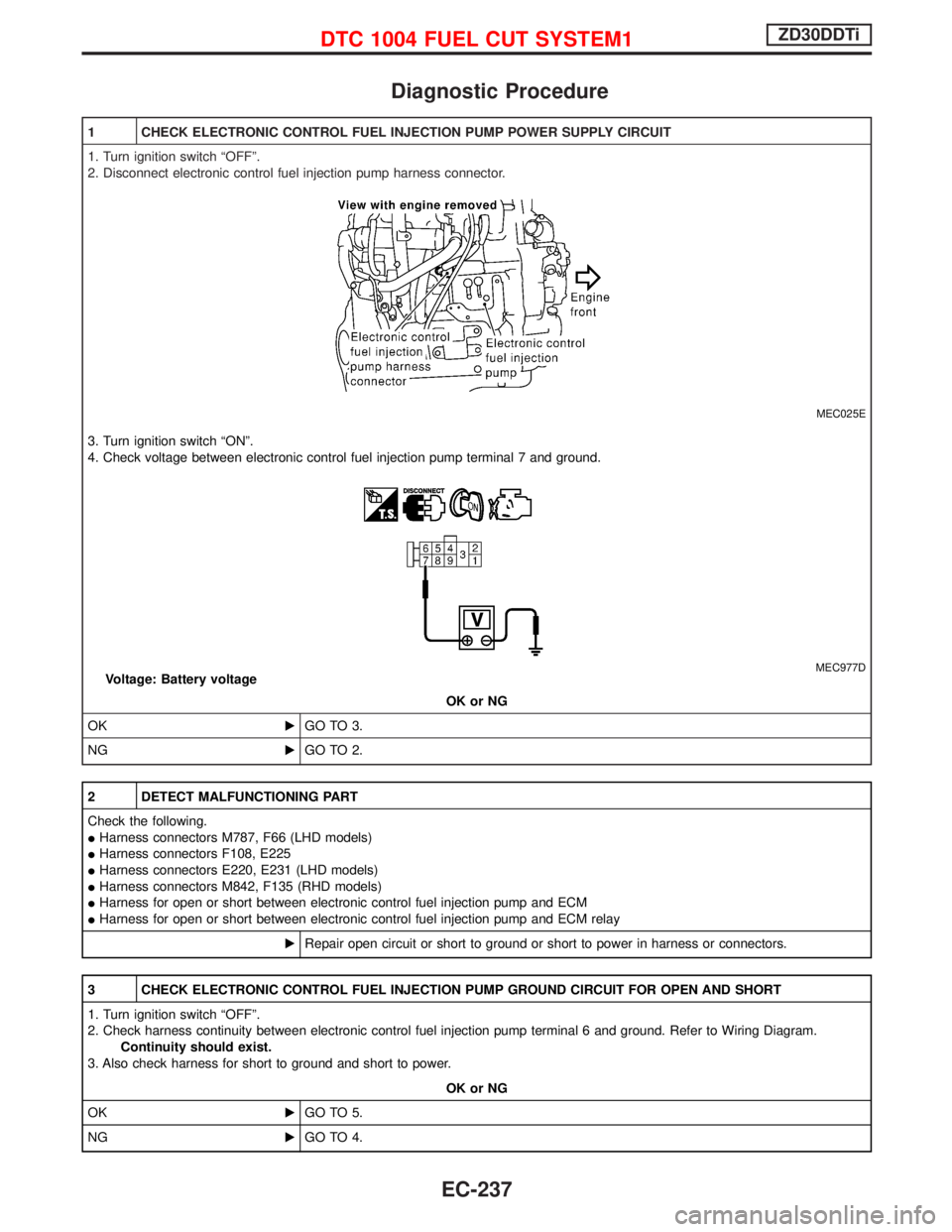
1 CHECK ELECTRONIC CONTROL FUEL INJECTION PUMP POWER SUPPLY CIRCUIT
1. Turn ignition switch ªOFFº.
2. Disconnect electronic control fuel injection pump harness connector.
MEC025E
3. Turn ignition switch ªONº.
4. Check voltage between electronic control fuel injection pump terminal 7 and ground.
MEC977DVoltage: Battery voltage
OK or NG
OKEGO TO 3.
NGEGO TO 2.
2 DETECT MALFUNCTIONING PART
Check the following.
IHarness connectors M787, F66 (LHD models)
IHarness connectors F108, E225
IHarness connectors E220, E231 (LHD models)
IHarness connectors M842, F135 (RHD models)
IHarness for open or short between electronic control fuel injection pump and ECM
IHarness for open or short between electronic control fuel injection pump and ECM relay
ERepair open circuit or short to ground or short to power in harness or connectors.
3 CHECK ELECTRONIC CONTROL FUEL INJECTION PUMP GROUND CIRCUIT FOR OPEN AND SHORT
1. Turn ignition switch ªOFFº.
2. Check harness continuity between electronic control fuel injection pump terminal 6 and ground. Refer to Wiring Diagram.
Continuity should exist.
3. Also check harness for short to ground and short to power.
OK or NG
OKEGO TO 5.
NGEGO TO 4.
DTC 1004 FUEL CUT SYSTEM1ZD30DDTi
EC-237
Page 700 of 1767
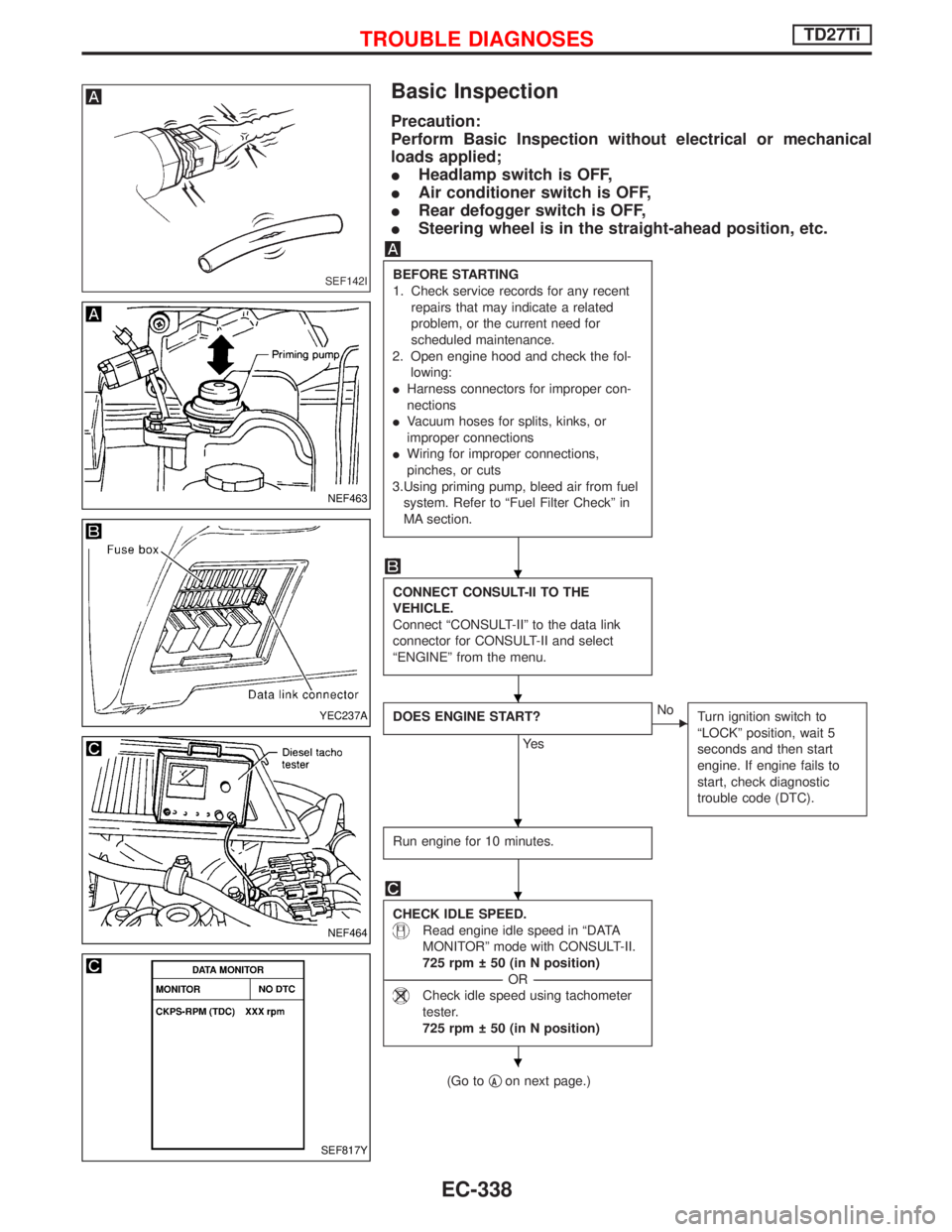
Basic Inspection
Precaution:
Perform Basic Inspection without electrical or mechanical
loads applied;
IHeadlamp switch is OFF,
IAir conditioner switch is OFF,
IRear defogger switch is OFF,
ISteering wheel is in the straight-ahead position, etc.
BEFORE STARTING
1. Check service records for any recent
repairs that may indicate a related
problem, or the current need for
scheduled maintenance.
2. Open engine hood and check the fol-
lowing:
IHarness connectors for improper con-
nections
IVacuum hoses for splits, kinks, or
improper connections
IWiring for improper connections,
pinches, or cuts
3.Using priming pump, bleed air from fuel
system. Refer to ªFuel Filter Checkº in
MA section.
CONNECT CONSULT-II TO THE
VEHICLE.
Connect ªCONSULT-IIº to the data link
connector for CONSULT-II and select
ªENGINEº from the menu.
DOES ENGINE START?
Ye s
ENo
Turn ignition switch to
ªLOCKº position, wait 5
seconds and then start
engine. If engine fails to
start, check diagnostic
trouble code (DTC).
Run engine for 10 minutes.
CHECK IDLE SPEED.
Read engine idle speed in ªDATA
MONITORº mode with CONSULT-II.
725 rpm 50 (in N position)
------------------------------------------------------------------------------------------------------------------------------------OR------------------------------------------------------------------------------------------------------------------------------------
Check idle speed using tachometer
tester.
725 rpm 50 (in N position)
(Go toqAon next page.)
SEF142I
NEF463
YEC237A
NEF464
SEF817Y
H
H
H
H
H
TROUBLE DIAGNOSESTD27Ti
EC-338
Page 736 of 1767
Diagnostic Procedure
INSPECTION START
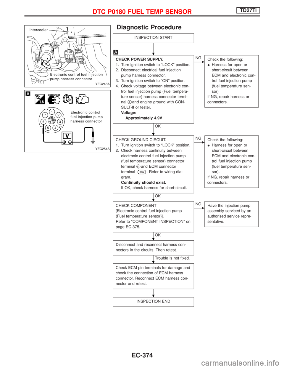
CHECK POWER SUPPLY.
1. Turn ignition switch to ªLOCKº position.
2. Disconnect electrical fuel injection
pump harness connector.
3. Turn ignition switch to ªONº position.
4. Check voltage between electronic con-
trol fuel injection pump (Fuel tempera-
ture sensor) harness connector termi-
nalq
6and engine ground with CON-
SULT-II or tester.
Voltage:
Approximately 4.9V
OK
ENG
Check the following:
IHarness for open or
short-circuit between
ECM and electronic con-
trol fuel injection pump
(fuel temperature sen-
sor)
If NG, repair harness or
connectors.
CHECK GROUND CIRCUIT.
1. Turn ignition switch to ªLOCKº position.
2. Check harness continuity between
electronic control fuel injection pump
(fuel temperature sensor) connector
terminalq
5and ECM connector
terminal
335. Refer to wiring dia-
gram.
Continuity should exist.
If OK, check harness for short-circuit.
OK
ENG
Check the following:
IHarness for open or
short-circuit between
ECM and electronic con-
trol fuel injection pump
(fuel temperature sen-
sor).
If NG, repair harness or
connectors.
CHECK COMPONENT
[Electronic control fuel injection pump
(Fuel temperature sensor)].
Refer to ªCOMPONENT INSPECTIONº on
page EC-375.
OK
ENG
Have the injection pump
assembly serviced by an
authorised service repre-
sentative.
Disconnect and reconnect harness con-
nectors in the circuits. Then retest.
Trouble is not fixed.
Check ECM pin terminals for damage and
check the connection of ECM harness
connector. Reconnect ECM harness con-
nector and retest.
INSPECTION END
YEC248A
YEC254A
H
H
H
H
H
H
DTC P0180 FUEL TEMP SENSORTD27Ti
EC-374