air flow NISSAN TERRANO 2002 Service Repair Manual
[x] Cancel search | Manufacturer: NISSAN, Model Year: 2002, Model line: TERRANO, Model: NISSAN TERRANO 2002Pages: 1767, PDF Size: 41.51 MB
Page 3 of 1767
AUTOMATIC TRANSMISSION
SECTION
AT
CONTENTS
PREPARATION AND PRECAUTIONS............................3
Special Service Tools ..................................................3
Supplemental Restraint System (SRS)²AIR
BAG²and²SEAT BELT PRE-TENSIONER²...............4
Precautions ..................................................................4
Service Notice or Precautions .....................................5
OVERALL SYSTEM........................................................6
A/T Electrical Parts Location .......................................6
Wiring Diagram - A/T -.................................................7
Cross-sectional View ...................................................8
Hydraulic Control Circuits ............................................9
Shift Mechanism ........................................................10
Control System ..........................................................12
ON BOARD DIAGNOSTIC SYSTEM
DESCRIPTION...............................................................14
Self-diagnosis ............................................................14
Diagnosis by CONSULT-II .........................................20
TROUBLE DIAGNOSIS - Introduction........................22
Introduction ................................................................22
Diagnostic Worksheet ................................................23
Work Flow ..................................................................26
TROUBLE DIAGNOSIS - Basic Inspection................27
A/T Fluid Check .........................................................27
Stall Test ....................................................................27
Line Pressure Test .....................................................30
Road Test...................................................................32
TROUBLE DIAGNOSIS - General Description...........43
Symptom Chart ..........................................................43
TCM Terminals and Reference Value........................46
TROUBLE DIAGNOSIS FOR VHCL SPEED
SEN×A/T.........................................................................49
Wiring Diagram - AT - VSSA/T ..................................49
Vehicle Speed Sensor×A/T (Revolution sensor) ........50
TROUBLE DIAGNOSIS FOR VHCL SPEED
SEN×MTR.......................................................................52
Wiring Diagram - AT - VSSMTR ................................52
Vehicle Speed Sensor×MTR ......................................54TROUBLE DIAGNOSIS FOR THROTTLE POSI
SEN................................................................................56
Wiring Diagram - AT - TPS ........................................56
Throttle (Accelerator) Position Sensor ......................60
TROUBLE DIAGNOSIS FOR SHIFT SOLENOID/V
A.....................................................................................62
Wiring Diagram - AT - SSV/A ....................................62
Shift Solenoid Valve A ...............................................63
TROUBLE DIAGNOSIS FOR SHIFT SOLENOID/V
B.....................................................................................65
Wiring Diagram - AT - SSV/B ....................................65
Shift Solenoid Valve B ...............................................66
TROUBLE DIAGNOSIS FOR OVERRUN CLUTCH
S/V..................................................................................68
Wiring Diagram - AT - OVRCSV................................68
Overrun Clutch Solenoid Valve .................................69
TROUBLE DIAGNOSIS FOR T/C CLUTCH SOL/V.....71
Wiring Diagram - AT - TCV........................................71
Torque Converter Clutch Solenoid Valve ..................72
TROUBLE DIAGNOSIS FOR BATT/FLUID TEMP
SEN................................................................................75
Wiring Diagram - AT - BA/FTS ..................................75
A/T Fluid Temperature Sensor and TCM Power
Source........................................................................76
TROUBLE DIAGNOSIS FOR ENGINE SPEED SIG....79
Wiring Diagram - AT - ENGSS ..................................79
Engine Speed Signal .................................................80
TROUBLE DIAGNOSIS FOR LINE PRESSURE
S/V..................................................................................82
Wiring Diagram - AT - LPSV......................................82
Line Pressure Solenoid Valve ...................................84
TROUBLE DIAGNOSIS FOR NON-DETECTABLE
ITEMS.............................................................................87
Wiring Diagram - AT - PNP/SW.................................87
Park/neutral Position, Overdrive Control or
Throttle (Accelerator) Position Switches ...................88
DIAGNOSTIC PROCEDURES FOR SYMPTOMS........94
Page 4 of 1767
1. SPORT Indicator Lamp Does Not Come On ........94
2. SPORT or SNOW Indicator Lamp Does Not
Come On...................................................................95
3. O/D OFF Indicator Lamp Does Not Come On......95
4. SPORT Indicator Lamp Does Not Come On ........96
5. Engine Cannot Be Started In²P²and²N²
Position......................................................................97
6. In²P²Position, Vehicle Moves Forward Or
Backward When Pushed...........................................97
7. In²N²Position, Vehicle Moves .............................98
8. Large Shock.²N²->²R²Position .........................99
9. Vehicle Does Not Creep Backward In²R²
Position....................................................................100
10. Vehicle Does Not Creep Forward In²D²,²2²
Or²1²Position.........................................................101
11. Vehicle Cannot Be Started From D
1.................102
12. A/T Does Not Shift: D
1-> D2Or Does Not
Kickdown: D
4-> D2..................................................103
13. A/T Does Not Shift: D
2-> D3............................104
14. A/T Does Not Shift: D
3-> D4.............................105
15. A/T Does Not Perform Lock-up .........................106
16. A/T Does Not Hold Lock-up Condition ..............107
17. Lock-up Is Not Released ...................................107
18. Engine Speed Does Not Return To Idle (Light
Braking D
4-> D3) .....................................................108
19. Vehicle Does Not Start From D
1.......................109
20. A/T Does Not Shift: D
2-> D1When
Depressing Accelerator Pedal................................. 110
21. A/T Does Not Shift: D
4-> D3, When
Overdrive Control Switch²ON²->²OFF²............... 111
22. A/T Does Not Shift: D
3-> 22, When Selector
Lever²D²->²2²Position......................................... 111
23. A/T Does Not Shift: 2
2-> 11, When Selector
Lever²2²->²1²Position ......................................... 112
24. Vehicle Does Not Decelerate By Engine
Brake........................................................................ 112
ON-VEHICLE SERVICE.............................................. 113Control Valve Assembly and Accumulators ............. 113
Revolution Sensor Replacement ............................. 114
Rear Oil Seal Replacement ..................................... 114
Parking Components Inspection.............................. 114
Park/neutral Position Switch Adjustment ................. 114
Manual Control Linkage Adjustment........................ 115
REMOVAL AND INSTALLATION................................ 116
Removal ................................................................... 116
Installation ................................................................ 117
MAJOR OVERHAUL................................................... 119
Oil Channel ..............................................................121
Locations of Needle Bearings, Thrust Washers
and Snap Rings .......................................................122
DISASSEMBLY............................................................123
Disassembly.............................................................123
REPAIR FOR COMPONENT PARTS..........................134
Oil Pump ..................................................................134
Control Valve Assembly ...........................................138
Control Valve Upper Body .......................................144
Control Valve Lower Body .......................................149
Reverse Clutch ........................................................151
High Clutch ..............................................................155
Forward and Overrun Clutches ...............................157
Low & Reverse Brake..............................................161
Forward Clutch Drum Assembly ..............................165
Rear Internal Gear and Forward Clutch Hub ..........168
Band Servo Piston Assembly ..................................171
Parking Pawl Components ......................................175
ASSEMBLY..................................................................177
Assembly (1) ............................................................177
Adjustment ...............................................................185
Assembly (2) ............................................................188
A/T FLUID COOLER SYSTEM...................................195
A/T Fluid Cooler.......................................................195
SERVICE DATA AND SPECIFICATIONS (SDS)........196
General Specifications .............................................196
Specifications and Adjustment.................................196
When you read wiring diagrams:
IRead GI section, ªHOW TO READ WIRING DIAGRAMSº.
ISee EL section, ªPOWER SUPPLY ROUTINGº for power distribution circuit.
When you perform trouble diagnoses, read GI section, ªHOW TO FOLLOW FLOW CHART IN
TROUBLE DIAGNOSESº and ªHOW TO PERFORM EFFICIENT DIAGNOSIS FOR AN ELECTRI-
CAL INCIDENTº.
CONTENTS(Cont'd)
AT- 2
Page 28 of 1767
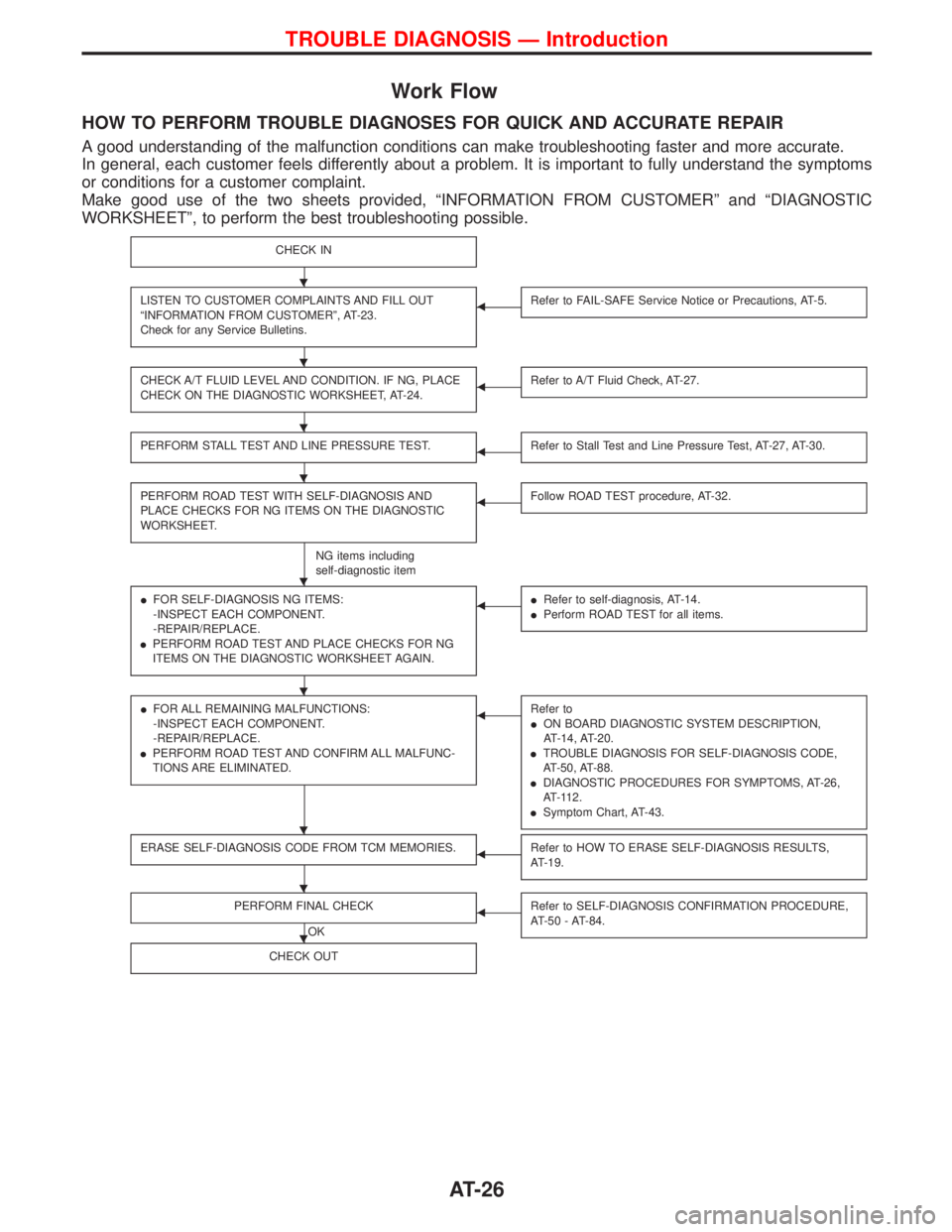
Work Flow
HOW TO PERFORM TROUBLE DIAGNOSES FOR QUICK AND ACCURATE REPAIR
A good understanding of the malfunction conditions can make troubleshooting faster and more accurate.
In general, each customer feels differently about a problem. It is important to fully understand the symptoms
or conditions for a customer complaint.
Make good use of the two sheets provided, ªINFORMATION FROM CUSTOMERº and ªDIAGNOSTIC
WORKSHEETº, to perform the best troubleshooting possible.
CHECK IN
LISTEN TO CUSTOMER COMPLAINTS AND FILL OUT
ªINFORMATION FROM CUSTOMERº, AT-23.
Check for any Service Bulletins.FRefer to FAIL-SAFE Service Notice or Precautions, AT-5.
CHECK A/T FLUID LEVEL AND CONDITION. IF NG, PLACE
CHECK ON THE DIAGNOSTIC WORKSHEET, AT-24.FRefer to A/T Fluid Check, AT-27.
PERFORM STALL TEST AND LINE PRESSURE TEST.FRefer to Stall Test and Line Pressure Test, AT-27, AT-30.
PERFORM ROAD TEST WITH SELF-DIAGNOSIS AND
PLACE CHECKS FOR NG ITEMS ON THE DIAGNOSTIC
WORKSHEET.
NG items including
self-diagnostic item
FFollow ROAD TEST procedure, AT-32.
IFOR SELF-DIAGNOSIS NG ITEMS:
-INSPECT EACH COMPONENT.
-REPAIR/REPLACE.
IPERFORM ROAD TEST AND PLACE CHECKS FOR NG
ITEMS ON THE DIAGNOSTIC WORKSHEET AGAIN.FIRefer to self-diagnosis, AT-14.
IPerform ROAD TEST for all items.
IFOR ALL REMAINING MALFUNCTIONS:
-INSPECT EACH COMPONENT.
-REPAIR/REPLACE.
IPERFORM ROAD TEST AND CONFIRM ALL MALFUNC-
TIONS ARE ELIMINATED.FRefer to
ION BOARD DIAGNOSTIC SYSTEM DESCRIPTION,
AT-14, AT-20.
ITROUBLE DIAGNOSIS FOR SELF-DIAGNOSIS CODE,
AT-50, AT-88.
IDIAGNOSTIC PROCEDURES FOR SYMPTOMS, AT-26,
AT-112.
ISymptom Chart, AT-43.
ERASE SELF-DIAGNOSIS CODE FROM TCM MEMORIES.FRefer to HOW TO ERASE SELF-DIAGNOSIS RESULTS,
AT-19.
PERFORM FINAL CHECK
OK
FRefer to SELF-DIAGNOSIS CONFIRMATION PROCEDURE,
AT-50 - AT-84.
CHECK OUT
H
H
H
H
H
H
H
H
H
TROUBLE DIAGNOSIS Ð Introduction
AT-26
Page 354 of 1767
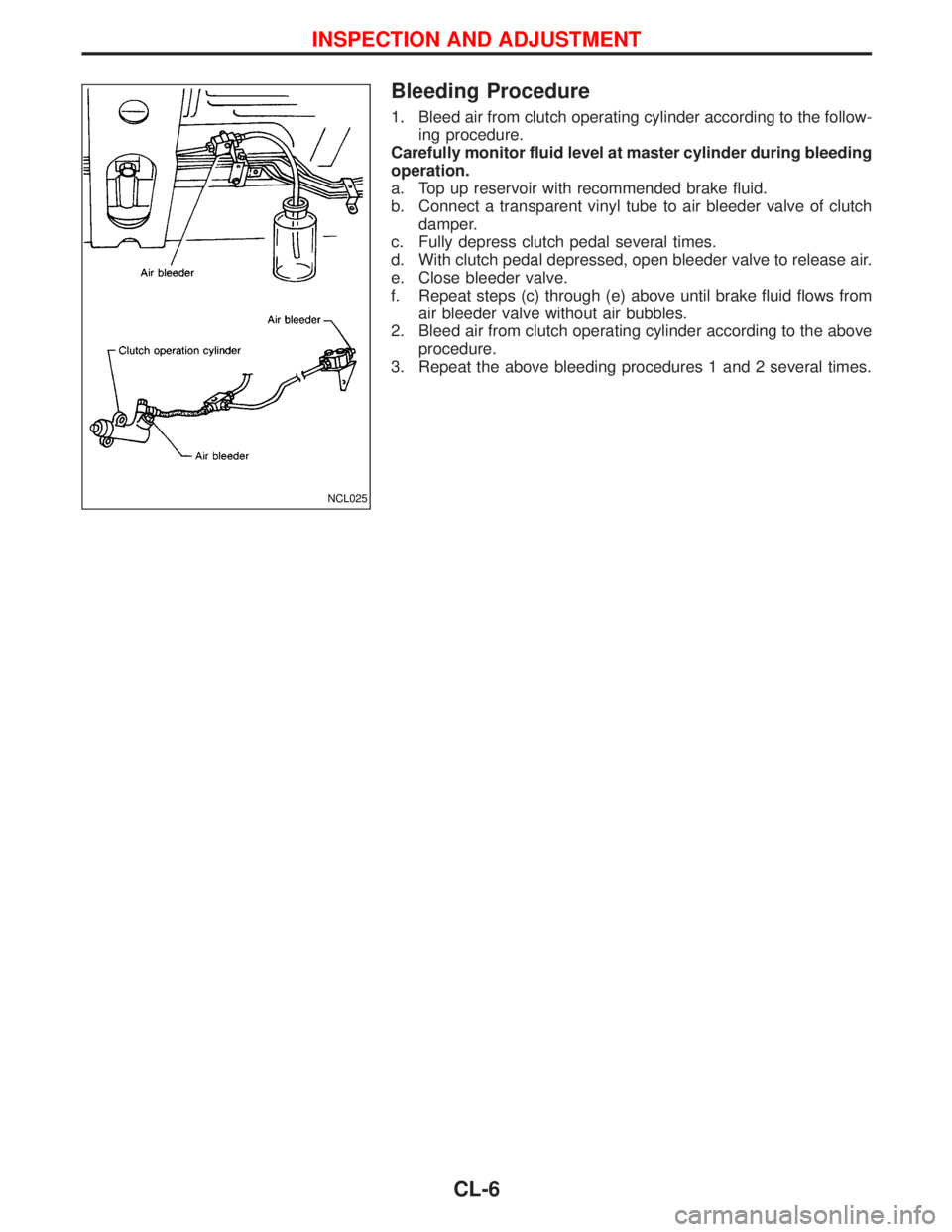
Bleeding Procedure
1. Bleed air from clutch operating cylinder according to the follow-
ing procedure.
Carefully monitor fluid level at master cylinder during bleeding
operation.
a. Top up reservoir with recommended brake fluid.
b. Connect a transparent vinyl tube to air bleeder valve of clutch
damper.
c. Fully depress clutch pedal several times.
d. With clutch pedal depressed, open bleeder valve to release air.
e. Close bleeder valve.
f. Repeat steps (c) through (e) above until brake fluid flows from
air bleeder valve without air bubbles.
2. Bleed air from clutch operating cylinder according to the above
procedure.
3. Repeat the above bleeding procedures 1 and 2 several times.
NCL025
INSPECTION AND ADJUSTMENT
CL-6
Page 363 of 1767
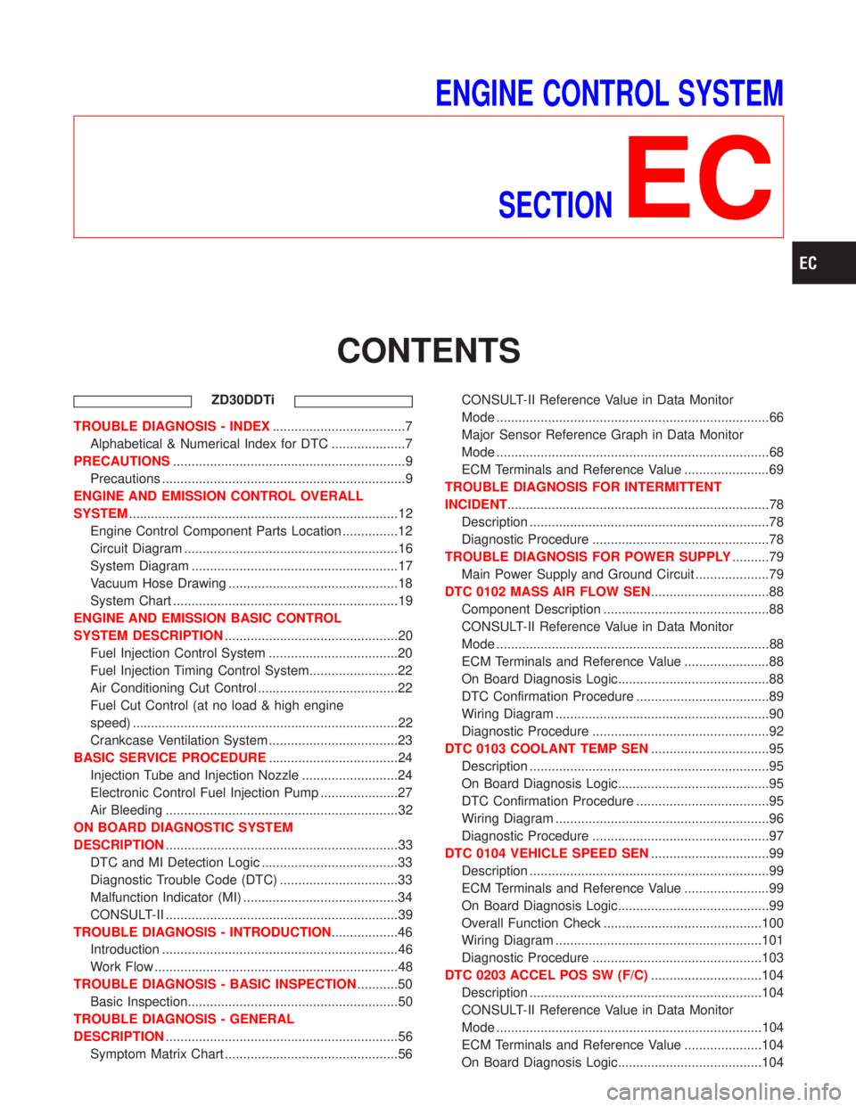
ENGINE CONTROL SYSTEM
SECTION
EC
CONTENTS
ZD30DDTi
TROUBLE DIAGNOSIS - INDEX....................................7
Alphabetical & Numerical Index for DTC ....................7
PRECAUTIONS...............................................................9
Precautions ..................................................................9
ENGINE AND EMISSION CONTROL OVERALL
SYSTEM.........................................................................12
Engine Control Component Parts Location ...............12
Circuit Diagram ..........................................................16
System Diagram ........................................................17
Vacuum Hose Drawing ..............................................18
System Chart .............................................................19
ENGINE AND EMISSION BASIC CONTROL
SYSTEM DESCRIPTION...............................................20
Fuel Injection Control System ...................................20
Fuel Injection Timing Control System........................22
Air Conditioning Cut Control ......................................22
Fuel Cut Control (at no load & high engine
speed) ........................................................................22
Crankcase Ventilation System ...................................23
BASIC SERVICE PROCEDURE...................................24
Injection Tube and Injection Nozzle ..........................24
Electronic Control Fuel Injection Pump .....................27
Air Bleeding ...............................................................32
ON BOARD DIAGNOSTIC SYSTEM
DESCRIPTION...............................................................33
DTC and MI Detection Logic .....................................33
Diagnostic Trouble Code (DTC) ................................33
Malfunction Indicator (MI) ..........................................34
CONSULT-II ...............................................................39
TROUBLE DIAGNOSIS - INTRODUCTION..................46
Introduction ................................................................46
Work Flow ..................................................................48
TROUBLE DIAGNOSIS - BASIC INSPECTION...........50
Basic Inspection.........................................................50
TROUBLE DIAGNOSIS - GENERAL
DESCRIPTION...............................................................56
Symptom Matrix Chart ...............................................56CONSULT-II Reference Value in Data Monitor
Mode ..........................................................................66
Major Sensor Reference Graph in Data Monitor
Mode ..........................................................................68
ECM Terminals and Reference Value .......................69
TROUBLE DIAGNOSIS FOR INTERMITTENT
INCIDENT.......................................................................78
Description .................................................................78
Diagnostic Procedure ................................................78
TROUBLE DIAGNOSIS FOR POWER SUPPLY..........79
Main Power Supply and Ground Circuit ....................79
DTC 0102 MASS AIR FLOW SEN................................88
Component Description .............................................88
CONSULT-II Reference Value in Data Monitor
Mode ..........................................................................88
ECM Terminals and Reference Value .......................88
On Board Diagnosis Logic.........................................88
DTC Confirmation Procedure ....................................89
Wiring Diagram ..........................................................90
Diagnostic Procedure ................................................92
DTC 0103 COOLANT TEMP SEN................................95
Description .................................................................95
On Board Diagnosis Logic.........................................95
DTC Confirmation Procedure ....................................95
Wiring Diagram ..........................................................96
Diagnostic Procedure ................................................97
DTC 0104 VEHICLE SPEED SEN................................99
Description .................................................................99
ECM Terminals and Reference Value .......................99
On Board Diagnosis Logic.........................................99
Overall Function Check ...........................................100
Wiring Diagram ........................................................101
Diagnostic Procedure ..............................................103
DTC 0203 ACCEL POS SW (F/C)..............................104
Description ...............................................................104
CONSULT-II Reference Value in Data Monitor
Mode ........................................................................104
ECM Terminals and Reference Value .....................104
On Board Diagnosis Logic.......................................104
Page 366 of 1767
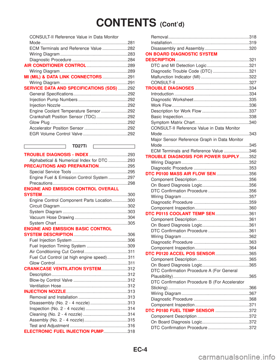
CONSULT-II Reference Value in Data Monitor
Mode ........................................................................281
ECM Terminals and Reference Value .....................282
Wiring Diagram ........................................................283
Diagnostic Procedure ..............................................284
AIR CONDITIONER CONTROL..................................289
Wiring Diagram ........................................................289
MI (MIL) & DATA LINK CONNECTORS.....................291
Wiring Diagram ........................................................291
SERVICE DATA AND SPECIFICATIONS (SDS)........292
General Specifications .............................................292
Injection Pump Numbers .........................................292
Injection Nozzle .......................................................292
Engine Coolant Temperature Sensor ......................292
Crankshaft Position Sensor (TDC) ..........................292
Glow Plug ................................................................292
Accelerator Position Sensor ....................................292
EGR Volume Control Valve .....................................292
TD27Ti
TROUBLE DIAGNOSIS - INDEX................................293
Alphabetical & Numerical Index for DTC ................293
PRECAUTIONS AND PREPARATION........................295
Special Service Tools ..............................................295
Engine Fuel & Emission Control System ................297
Precautions ..............................................................298
ENGINE AND EMISSION CONTROL OVERALL
SYSTEM.......................................................................300
Engine Control Component Parts Location .............300
Circuit Diagram ........................................................302
System Diagram ......................................................303
Vacuum Hose Drawing ............................................304
System Chart ...........................................................305
ENGINE AND EMISSION BASIC CONTROL
SYSTEM DESCRIPTION.............................................306
Fuel Injection System ..............................................306
Fuel Injection Timing System ..................................309
Air Conditioning Cut Control .................................... 311
Fuel Cut Control (at high engine speed) ................. 311
Glow Control ............................................................ 311
CRANKCASE VENTILATION SYSTEM......................312
Description ...............................................................312
Blow-by Control Valve .............................................312
Ventilation Hose .......................................................312
INJECTION NOZZLE...................................................313
Removal and Installation .........................................313
Disassembly (No.2-4nozzle) ...............................313
Inspection (No.2-4nozzle) ...................................314
Cleaning (No.2-4nozzle) .....................................314
Assembly (No.2-4nozzle) ....................................315
Test and Adjustment ................................................316
ELECTRONIC FUEL INJECTION PUMP....................318Removal ...................................................................318
Installation ................................................................319
Disassembly and Assembly .....................................320
ON BOARD DIAGNOSTIC SYSTEM
DESCRIPTION.............................................................321
DTC and MI Detection Logic ...................................321
Diagnostic Trouble Code (DTC) ..............................321
Malfunction Indicator (MI) ........................................322
CONSULT-II .............................................................327
TROUBLE DIAGNOSES.............................................334
Introduction ..............................................................334
Diagnostic Worksheet ..............................................335
Work Flow ................................................................336
Description for Work Flow .......................................337
Basic Inspection.......................................................338
Symptom Matrix Chart .............................................340
CONSULT-II Reference Value in Data Monitor
Mode ........................................................................343
Major Sensor Reference Graph in Data Monitor
Mode ........................................................................345
ECM Terminals and Reference Value .....................346
TROUBLE DIAGNOSIS FOR POWER SUPPLY........352
Wiring Diagram ........................................................352
Diagnostic Procedure ..............................................353
DTC P0100 MASS AIR FLOW SEN...........................356
Component Description ...........................................356
On Board Diagnosis Logic.......................................356
DTC Confirmation Procedure ..................................356
Wiring Diagram ........................................................357
Diagnostic Procedure ..............................................359
Component Inspection .............................................360
DTC P0115 COOLANT TEMP SEN............................361
Component Description ...........................................361
On Board Diagnosis Logic.......................................361
DTC Confirmation Procedure ..................................361
Wiring Diagram ........................................................362
Diagnostic Procedure ..............................................363
Component Inspection .............................................364
DTC P0120 ACCEL POS SENSOR............................365
Component Description ...........................................365
On Board Diagnosis Logic.......................................365
DTC Confirmation Procedure A (For General
Plausibility) ...............................................................365
DTC Confirmation Procedure B (For Accelerator
Sticking) ...................................................................366
Wiring Diagram ........................................................367
Diagnostic Procedure ..............................................368
Component Inspection .............................................371
DTC P0180 FUEL TEMP SENSOR............................372
Component Description ...........................................372
On Board Diagnosis Logic.......................................372
DTC Confirmation Procedure ..................................372
CONTENTS(Cont'd)
EC-4
Page 369 of 1767
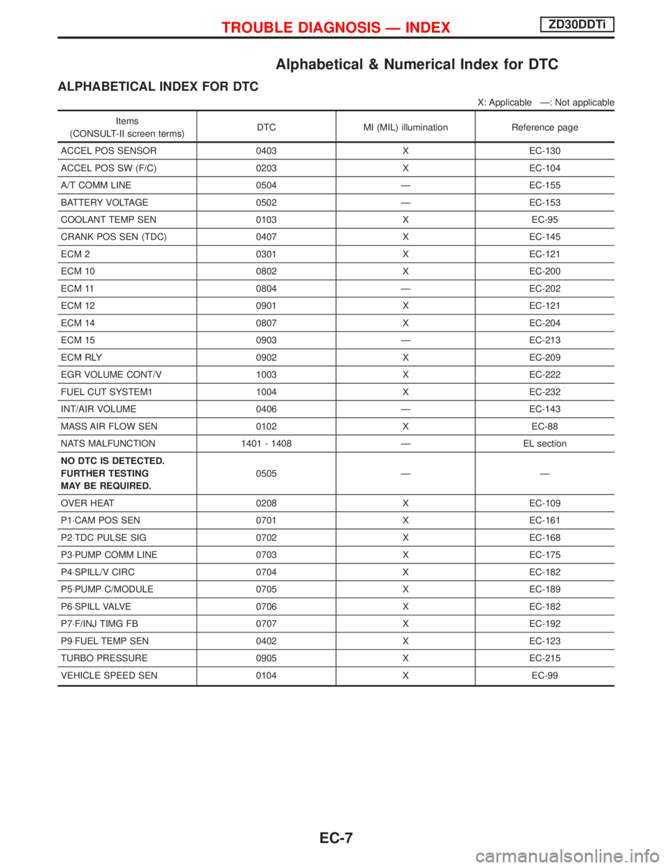
Alphabetical & Numerical Index for DTC
ALPHABETICAL INDEX FOR DTC
X: Applicable Ð: Not applicable
Items
(CONSULT-II screen terms)DTC MI (MIL) illumination Reference page
ACCEL POS SENSOR 0403 X EC-130
ACCEL POS SW (F/C) 0203 X EC-104
A/T COMM LINE 0504 Ð EC-155
BATTERY VOLTAGE 0502 Ð EC-153
COOLANT TEMP SEN 0103 X EC-95
CRANK POS SEN (TDC) 0407 X EC-145
ECM 2 0301 X EC-121
ECM 10 0802 X EC-200
ECM 11 0804 Ð EC-202
ECM 12 0901 X EC-121
ECM 14 0807 X EC-204
ECM 15 0903 Ð EC-213
ECM RLY 0902 X EC-209
EGR VOLUME CONT/V 1003 X EC-222
FUEL CUT SYSTEM1 1004 X EC-232
INT/AIR VOLUME 0406 Ð EC-143
MASS AIR FLOW SEN 0102 X EC-88
NATS MALFUNCTION 1401 - 1408 Ð EL section
NO DTC IS DETECTED.
FURTHER TESTING
MAY BE REQUIRED.0505 Ð Ð
OVER HEAT 0208 X EC-109
P1×CAM POS SEN 0701 X EC-161
P2×TDC PULSE SIG 0702 X EC-168
P3×PUMP COMM LINE 0703 X EC-175
P4×SPILL/V CIRC 0704 X EC-182
P5×PUMP C/MODULE 0705 X EC-189
P6×SPILL VALVE 0706 X EC-182
P7×F/INJ TIMG FB 0707 X EC-192
P9×FUEL TEMP SEN 0402 X EC-123
TURBO PRESSURE 0905 X EC-215
VEHICLE SPEED SEN 0104 X EC-99
TROUBLE DIAGNOSIS Ð INDEXZD30DDTi
EC-7
Page 370 of 1767
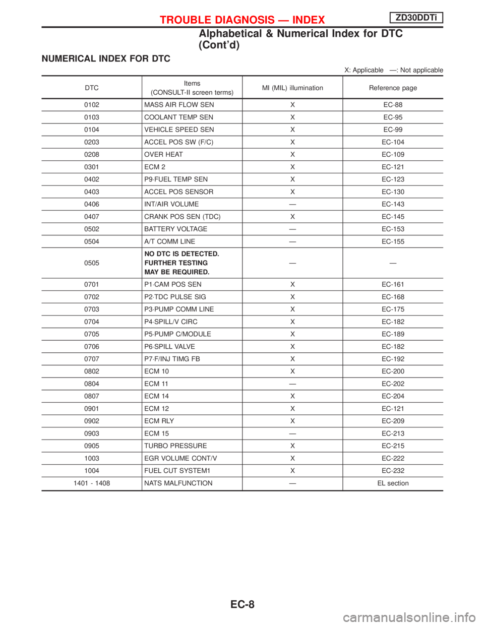
NUMERICAL INDEX FOR DTC
X: Applicable Ð: Not applicable
DTCItems
(CONSULT-II screen terms)MI (MIL) illumination Reference page
0102 MASS AIR FLOW SEN X EC-88
0103 COOLANT TEMP SEN X EC-95
0104 VEHICLE SPEED SEN X EC-99
0203 ACCEL POS SW (F/C) X EC-104
0208 OVER HEAT X EC-109
0301 ECM 2 X EC-121
0402 P9×FUEL TEMP SEN X EC-123
0403 ACCEL POS SENSOR X EC-130
0406 INT/AIR VOLUME Ð EC-143
0407 CRANK POS SEN (TDC) X EC-145
0502 BATTERY VOLTAGE Ð EC-153
0504 A/T COMM LINE Ð EC-155
0505NO DTC IS DETECTED.
FURTHER TESTING
MAY BE REQUIRED.ÐÐ
0701 P1×CAM POS SEN X EC-161
0702 P2×TDC PULSE SIG X EC-168
0703 P3×PUMP COMM LINE X EC-175
0704 P4×SPILL/V CIRC X EC-182
0705 P5×PUMP C/MODULE X EC-189
0706 P6×SPILL VALVE X EC-182
0707 P7×F/INJ TIMG FB X EC-192
0802 ECM 10 X EC-200
0804 ECM 11 Ð EC-202
0807 ECM 14 X EC-204
0901 ECM 12 X EC-121
0902 ECM RLY X EC-209
0903 ECM 15 Ð EC-213
0905 TURBO PRESSURE X EC-215
1003 EGR VOLUME CONT/V X EC-222
1004 FUEL CUT SYSTEM1 X EC-232
1401 - 1408 NATS MALFUNCTION Ð EL section
TROUBLE DIAGNOSIS Ð INDEXZD30DDTi
Alphabetical & Numerical Index for DTC
(Cont'd)
EC-8
Page 381 of 1767
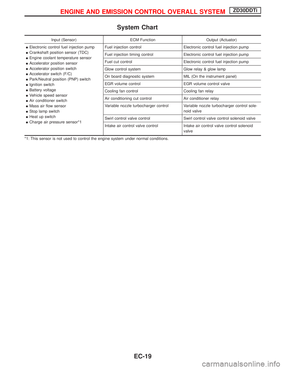
System Chart
Input (Sensor) ECM Function Output (Actuator)
IElectronic control fuel injection pump
ICrankshaft position sensor (TDC)
IEngine coolant temperature sensor
IAccelerator position sensor
IAccelerator position switch
IAccelerator switch (F/C)
IPark/Neutral position (PNP) switch
IIgnition switch
IBattery voltage
IVehicle speed sensor
IAir conditioner switch
IMass air flow sensor
IStop lamp switch
IHeat up switch
ICharge air pressure sensor*1Fuel injection control Electronic control fuel injection pump
Fuel injection timing control Electronic control fuel injection pump
Fuel cut control Electronic control fuel injection pump
Glow control system Glow relay & glow lamp
On board diagnostic system MIL (On the instrument panel)
EGR volume control EGR volume control valve
Cooling fan control Cooling fan relay
Air conditioning cut control Air conditioner relay
Variable nozzle turbocharger control Variable nozzle turbocharger control sole-
noid valve
Swirl control valve control Swirl control valve control solenoid valve
Intake air control valve control Intake air control valve control solenoid
valve
*1: This sensor is not used to control the engine system under normal conditions.
ENGINE AND EMISSION CONTROL OVERALL SYSTEMZD30DDTi
EC-19
Page 383 of 1767
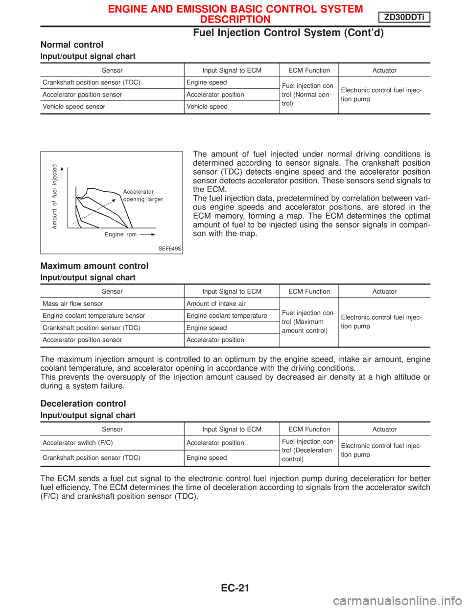
Normal control
Input/output signal chart
Sensor Input Signal to ECM ECM Function Actuator
Crankshaft position sensor (TDC) Engine speed
Fuel injection con-
trol (Normal con-
trol)Electronic control fuel injec-
tion pump Accelerator position sensor Accelerator position
Vehicle speed sensor Vehicle speed
The amount of fuel injected under normal driving conditions is
determined according to sensor signals. The crankshaft position
sensor (TDC) detects engine speed and the accelerator position
sensor detects accelerator position. These sensors send signals to
the ECM.
The fuel injection data, predetermined by correlation between vari-
ous engine speeds and accelerator positions, are stored in the
ECM memory, forming a map. The ECM determines the optimal
amount of fuel to be injected using the sensor signals in compari-
son with the map.
Maximum amount control
Input/output signal chart
Sensor Input Signal to ECM ECM Function Actuator
Mass air flow sensor Amount of intake air
Fuel injection con-
trol (Maximum
amount control)Electronic control fuel injec-
tion pump Engine coolant temperature sensor Engine coolant temperature
Crankshaft position sensor (TDC) Engine speed
Accelerator position sensor Accelerator position
The maximum injection amount is controlled to an optimum by the engine speed, intake air amount, engine
coolant temperature, and accelerator opening in accordance with the driving conditions.
This prevents the oversupply of the injection amount caused by decreased air density at a high altitude or
during a system failure.
Deceleration control
Input/output signal chart
Sensor Input Signal to ECM ECM Function Actuator
Accelerator switch (F/C) Accelerator positionFuel injection con-
trol (Deceleration
control)Electronic control fuel injec-
tion pump
Crankshaft position sensor (TDC) Engine speed
The ECM sends a fuel cut signal to the electronic control fuel injection pump during deceleration for better
fuel efficiency. The ECM determines the time of deceleration according to signals from the accelerator switch
(F/C) and crankshaft position sensor (TDC).
SEF649S
ENGINE AND EMISSION BASIC CONTROL SYSTEM
DESCRIPTIONZD30DDTi
Fuel Injection Control System (Cont'd)
EC-21