automatic transmission NISSAN TERRANO 2002 Service Repair Manual
[x] Cancel search | Manufacturer: NISSAN, Model Year: 2002, Model line: TERRANO, Model: NISSAN TERRANO 2002Pages: 1767, PDF Size: 41.51 MB
Page 1 of 1767
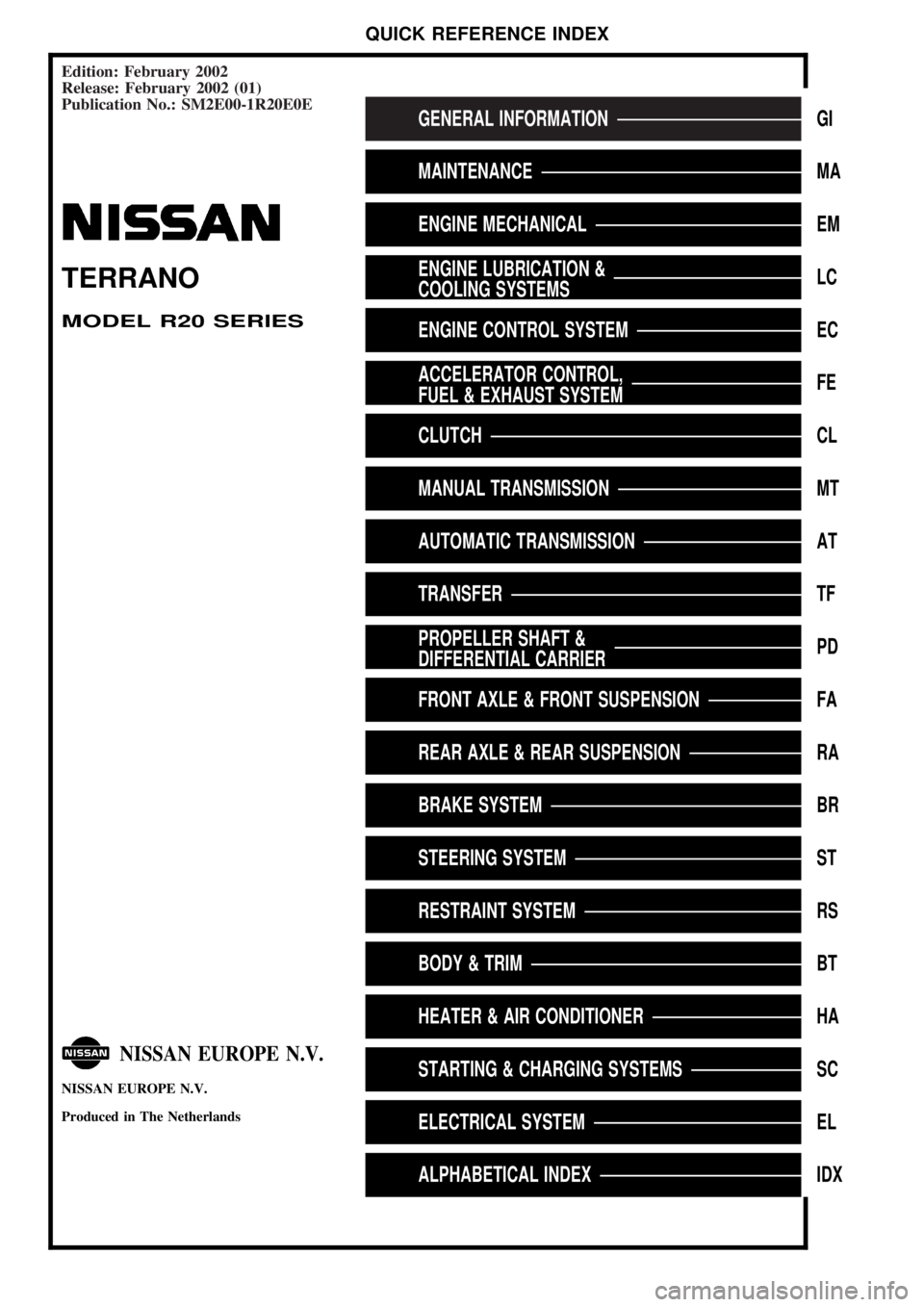
Edition: February 2002
Release: February 2002 (01)
Publication No.: SM2E00-1R20E0E
GENERAL INFORMATIONGI
MAINTENANCEMA
ENGINE MECHANICALEM
ENGINE LUBRICATION &
COOLING SYSTEMSLC
ENGINE CONTROL SYSTEMEC
ACCELERATOR CONTROL,
FUEL & EXHAUST SYSTEMFE
CLUTCHCL
MANUAL TRANSMISSIONMT
AUTOMATIC TRANSMISSIONAT
TRANSFERTF
PROPELLER SHAFT &
DIFFERENTIAL CARRIERPD
FRONT AXLE & FRONT SUSPENSIONFA
REAR AXLE & REAR SUSPENSIONRA
BRAKE SYSTEMBR
STEERING SYSTEMST
RESTRAINT SYSTEMRS
BODY & TRIMBT
HEATER & AIR CONDITIONERHA
STARTING & CHARGING SYSTEMSSC
ELECTRICAL SYSTEMEL
ALPHABETICAL INDEXIDX
TERRANO
MODEL R20 SERIES
NISSAN EUROPE N.V.
NISSAN EUROPE N.V.
Produced in The Netherlands
QUICK REFERENCE INDEX
Page 3 of 1767
AUTOMATIC TRANSMISSION
SECTION
AT
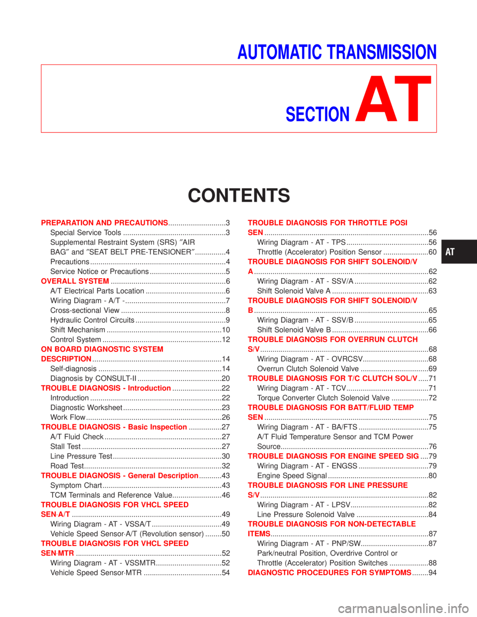
CONTENTS
PREPARATION AND PRECAUTIONS............................3
Special Service Tools ..................................................3
Supplemental Restraint System (SRS)²AIR
BAG²and²SEAT BELT PRE-TENSIONER²...............4
Precautions ..................................................................4
Service Notice or Precautions .....................................5
OVERALL SYSTEM........................................................6
A/T Electrical Parts Location .......................................6
Wiring Diagram - A/T -.................................................7
Cross-sectional View ...................................................8
Hydraulic Control Circuits ............................................9
Shift Mechanism ........................................................10
Control System ..........................................................12
ON BOARD DIAGNOSTIC SYSTEM
DESCRIPTION...............................................................14
Self-diagnosis ............................................................14
Diagnosis by CONSULT-II .........................................20
TROUBLE DIAGNOSIS - Introduction........................22
Introduction ................................................................22
Diagnostic Worksheet ................................................23
Work Flow ..................................................................26
TROUBLE DIAGNOSIS - Basic Inspection................27
A/T Fluid Check .........................................................27
Stall Test ....................................................................27
Line Pressure Test .....................................................30
Road Test...................................................................32
TROUBLE DIAGNOSIS - General Description...........43
Symptom Chart ..........................................................43
TCM Terminals and Reference Value........................46
TROUBLE DIAGNOSIS FOR VHCL SPEED
SEN×A/T.........................................................................49
Wiring Diagram - AT - VSSA/T ..................................49
Vehicle Speed Sensor×A/T (Revolution sensor) ........50
TROUBLE DIAGNOSIS FOR VHCL SPEED
SEN×MTR.......................................................................52
Wiring Diagram - AT - VSSMTR ................................52
Vehicle Speed Sensor×MTR ......................................54TROUBLE DIAGNOSIS FOR THROTTLE POSI
SEN................................................................................56
Wiring Diagram - AT - TPS ........................................56
Throttle (Accelerator) Position Sensor ......................60
TROUBLE DIAGNOSIS FOR SHIFT SOLENOID/V
A.....................................................................................62
Wiring Diagram - AT - SSV/A ....................................62
Shift Solenoid Valve A ...............................................63
TROUBLE DIAGNOSIS FOR SHIFT SOLENOID/V
B.....................................................................................65
Wiring Diagram - AT - SSV/B ....................................65
Shift Solenoid Valve B ...............................................66
TROUBLE DIAGNOSIS FOR OVERRUN CLUTCH
S/V..................................................................................68
Wiring Diagram - AT - OVRCSV................................68
Overrun Clutch Solenoid Valve .................................69
TROUBLE DIAGNOSIS FOR T/C CLUTCH SOL/V.....71
Wiring Diagram - AT - TCV........................................71
Torque Converter Clutch Solenoid Valve ..................72
TROUBLE DIAGNOSIS FOR BATT/FLUID TEMP
SEN................................................................................75
Wiring Diagram - AT - BA/FTS ..................................75
A/T Fluid Temperature Sensor and TCM Power
Source........................................................................76
TROUBLE DIAGNOSIS FOR ENGINE SPEED SIG....79
Wiring Diagram - AT - ENGSS ..................................79
Engine Speed Signal .................................................80
TROUBLE DIAGNOSIS FOR LINE PRESSURE
S/V..................................................................................82
Wiring Diagram - AT - LPSV......................................82
Line Pressure Solenoid Valve ...................................84
TROUBLE DIAGNOSIS FOR NON-DETECTABLE
ITEMS.............................................................................87
Wiring Diagram - AT - PNP/SW.................................87
Park/neutral Position, Overdrive Control or
Throttle (Accelerator) Position Switches ...................88
DIAGNOSTIC PROCEDURES FOR SYMPTOMS........94
Page 12 of 1767
Shift Mechanism
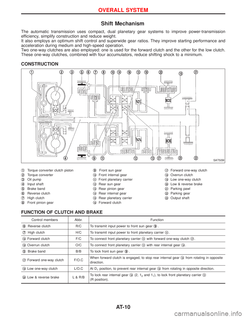
The automatic transmission uses compact, dual planetary gear systems to improve power-transmission
efficiency, simplify construction and reduce weight.
It also employs an optimum shift control and superwide gear ratios. They improve starting performance and
acceleration during medium and high-speed operation.
Two one-way clutches are also employed: one is used for the forward clutch and the other for the low clutch.
These one-way clutches, combined with four accumulators, reduce shifting shock to a minimum.
CONSTRUCTION
q1Torque converter clutch piston
q
2Torque converter
q
3Oil pump
q
4Input shaft
q
5Brake band
q
6Reverse clutch
q
7High clutch
q
8Front pinion gearq
9Front sun gear
q
10Front internal gear
q
11Front planetary carrier
q
12Rear sun gear
q
13Rear pinion gear
q
14Rear internal gear
q
15Rear planetary carrier
q
16Forward clutchq
17Forward one-way clutch
q
18Overrun clutch
q
19Low one-way clutch
q
20Low & reverse brake
q
21Parking pawl
q
22Parking gear
q
23Output shaft
FUNCTION OF CLUTCH AND BRAKE
Control members Abbr. Function
q
6Reverse clutch R/C To transmit input power to front sun gearq9.
q
7High clutch H/C To transmit input power to front planetary carrierq11.
q
16Forward clutch F/C To connect front planetary carrierq11with forward one-way clutchq17.
q
18Overrun clutch O/C To connect front planetary carrierq11with rear internal gearq14.
q
5Brake band B/B To lock front sun gearq9.
q
17Forward one-way clutch F/O.CWhen forward clutch is engaged, to stop rear internal gearq14from rotating in opposite
direction.
q
19Low one-way clutch L/O.C At D1position, to prevent rear internal gearq14from rotating in opposite direction.
q
20Low & reverse brake L & R/BTo lock rear internal gearq14(2, 12and 11), to lock front planetary carrierq11
(R position).
SAT509I
OVERALL SYSTEM
AT-10
Page 13 of 1767
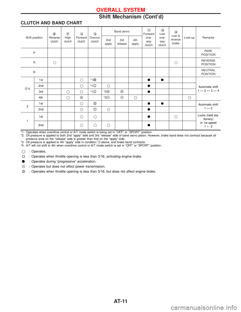
CLUTCH AND BAND CHART
Shift positionq6Reverse
clutchq7High
clutchq16Forward
clutchq18Overrun
clutchBand servoq
17Forward
one-
way
clutchq19Low
one-
way
clutchq20Low &
reverse
brakeLock-up Remarks
2nd
apply3rd
release4th
apply
PPARK
POSITION
RqqREVERSE
POSITION
NNEUTRAL
POSITION
D*41stq*1
vv
Automatic shift
1)2)3)4 2ndq*1
qv
3rdqq*1
*2v
4thq
*3qq
21stq
vv
Automatic shift
1)2
2ndq
qv
11stqqvqLocks (held sta-
tionary)
in 1st speed
1+2 2ndqqqv
*1: Operates when overdrive control or A/T mode switch is being set in ªOFFº or ªSPORTº position.
*2: Oil pressure is applied to both 2nd ªapplyº side and 3rd ªreleaseº side of band servo piston. However, brake band does not contract because oil
pressure area on the ªreleaseº side is greater than that on the ªapplyº side.
*3: Oil pressure is applied to 4th ªapplyº side in condition *2 above, and brake band contracts.
*4: A/T will not shift to 4th when overdrive control or A/T mode switch is set in ªOFFº or ªSPORTº position.
q: Operates.
: Operates when throttle opening is less than 3/16, activating engine brake.
v: Operates during ªprogressiveº acceleration.
: Operates but does not affect power transmission.
: Operates when throttle opening is less than 3/16, but does not affect engine brake.
OVERALL SYSTEM
Shift Mechanism (Cont'd)
AT-11
Page 14 of 1767
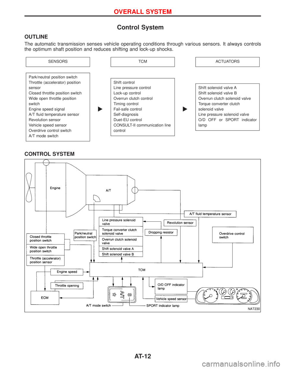
Control System
OUTLINE
The automatic transmission senses vehicle operating conditions through various sensors. It always controls
the optimum shaft position and reduces shifting and lock-up shocks.
SENSORSTCMACTUATORS
Park/neutral position switch
Throttle (accelerator) position
sensor
Closed throttle position switch
Wide open throttle position
switch
Engine speed signal
A/T fluid temperature sensor
Revolution sensor
Vehicle speed sensor
Overdrive control switch
A/T mode switch
E
Shift control
Line pressure control
Lock-up control
Overrun clutch control
Timing control
Fail-safe control
Self-diagnosis
Duet-EU control
CONSULT-II communication line
control
E
Shift solenoid valve A
Shift solenoid valve B
Overrun clutch solenoid valve
Torque converter clutch
solenoid valve
Line pressure solenoid valve
O/D OFF or SPORT indicator
lamp
CONTROL SYSTEM
NAT230
OVERALL SYSTEM
AT-12
Page 198 of 1767
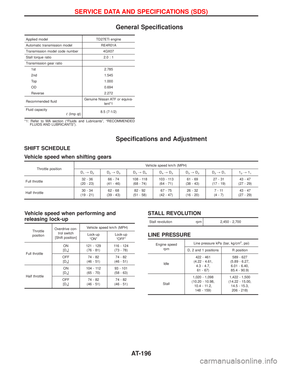
General Specifications
Applied model TD27ETi engine
Automatic transmission model RE4R01A
Transmission model code number 4GX07
Stall torque ratio 2.0 : 1
Transmission gear ratio
1st 2.785
2nd 1.545
Top 1.000
OD 0.694
Reverse 2.272
Recommended fluidGenuine Nissan ATF or equiva-
lent*1
Fluid capacity
(Imp qt)8.5 (7-1/2)
*1: Refer to MA section (ªFluids and Lubricantsº, ªRECOMMENDED
FLUIDS AND LUBRICANTSº).
Specifications and Adjustment
SHIFT SCHEDULE
Vehicle speed when shifting gears
Throttle positionVehicle speed km/h (MPH)
D1,D2D2,D3D3,D4D4,D3D3,D2D2,D112,11
Full throttle32-36
(20 - 23)66-74
(41 - 46)108 - 118
(68 - 74)103 - 113
(64 - 71)61-69
(38 - 43)27-31
(17 - 19)43-47
(27 - 29)
Half throttle30-34
(19 - 21)62-68
(39 - 43)82-92
(51 - 58)67-75
(42 - 47)26-32
(16 - 20)7-11
(4-7)43-47
(27 - 29)
Vehicle speed when performing and
releasing lock-up
Throttle
positionOverdrive con-
trol switch
[Shift position]Vehicle speed km/h (MPH)
Lock-up
ªONºLock-up
ªOFFº
Full throttleON
[D
4]121 - 129
(76 - 81)116 - 124
(73 - 78)
OFF
[D
3]74-82
(46 - 51)74-82
(46 - 51)
Half throttleON
[D
4]104 - 112
(65 - 70)93 - 101
(58 - 63)
OFF
[D
3]74-82
(46 - 51)74-82
(46 - 51)
STALL REVOLUTION
Stall revolution rpm 2,450 - 2,700
LINE PRESSURE
Engine speed
rpmLine pressure kPa (bar, kg/cm2, psi)
D, 2 and 1 positions R position
Idle422 - 461
(4.22 - 4.61,
4.3 - 4.7,
61 - 67)589 - 627
(5.89 - 6.27,
6.01 - 6.40,
85.4 - 90.9)
Stall1,020 - 1,098
(10.20 - 10.98,
10.4 - 11.2,
148 - 159)1,422 - 1,500
(14.22 - 15.00,
14.5 - 15.3,
206 - 218)
SERVICE DATA AND SPECIFICATIONS (SDS)
AT-196
Page 1323 of 1767
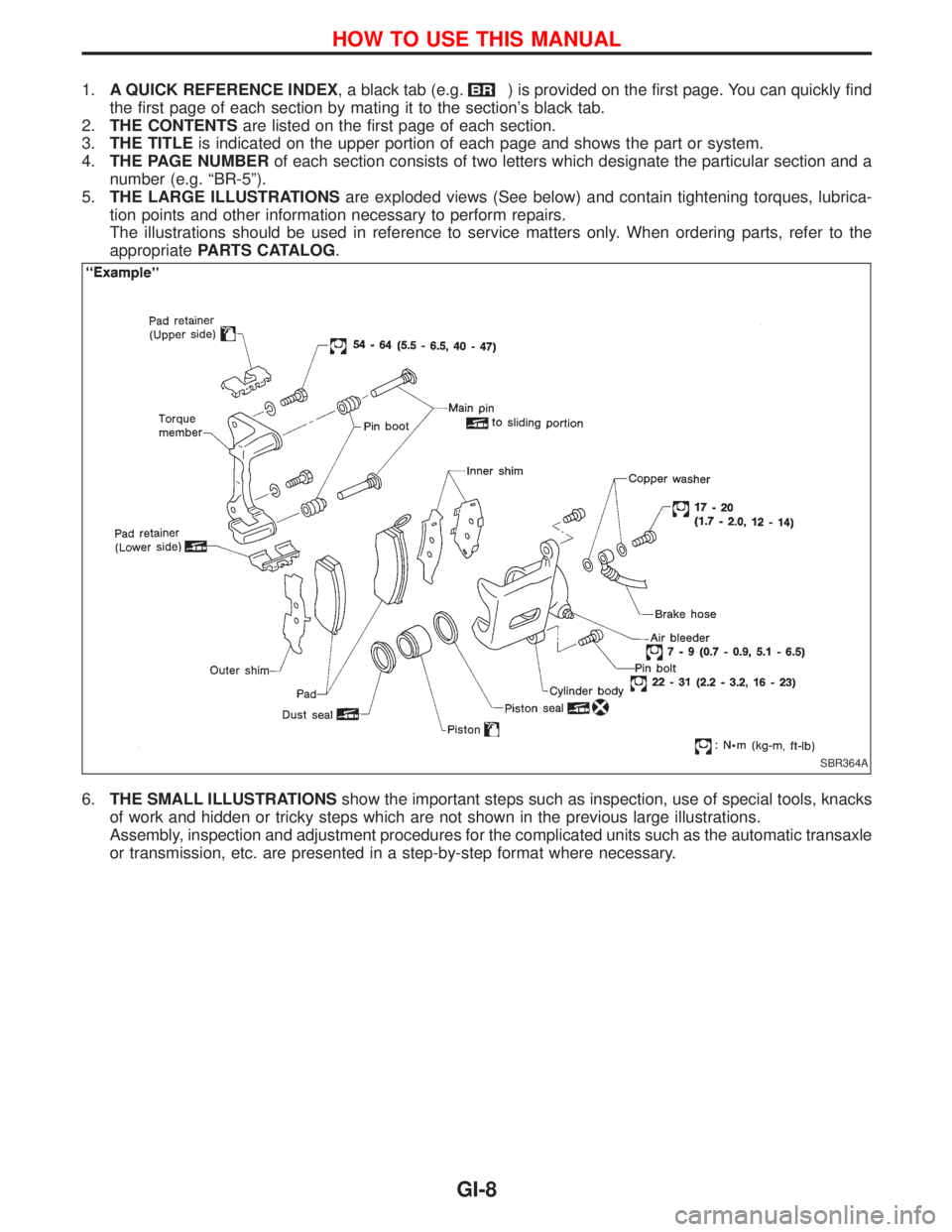
1.A QUICK REFERENCE INDEX, a black tab (e.g.) is provided on the first page. You can quickly find
the first page of each section by mating it to the section's black tab.
2.THE CONTENTSare listed on the first page of each section.
3.THE TITLEis indicated on the upper portion of each page and shows the part or system.
4.THE PAGE NUMBERof each section consists of two letters which designate the particular section and a
number (e.g. ªBR-5º).
5.THE LARGE ILLUSTRATIONSare exploded views (See below) and contain tightening torques, lubrica-
tion points and other information necessary to perform repairs.
The illustrations should be used in reference to service matters only. When ordering parts, refer to the
appropriatePARTS CATALOG.
6.THE SMALL ILLUSTRATIONSshow the important steps such as inspection, use of special tools, knacks
of work and hidden or tricky steps which are not shown in the previous large illustrations.
Assembly, inspection and adjustment procedures for the complicated units such as the automatic transaxle
or transmission, etc. are presented in a step-by-step format where necessary.
SBR364A
HOW TO USE THIS MANUAL
GI-8
Page 1324 of 1767
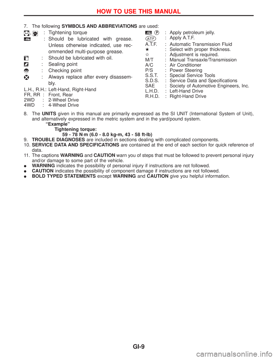
7. The followingSYMBOLS AND ABBREVIATIONSare used:
,: Tightening torque
: Should be lubricated with grease.
Unless otherwise indicated, use rec-
ommended multi-purpose grease.
: Should be lubricated with oil.
: Sealing point
: Checking point
: Always replace after every disassem-
bly.
L.H., R.H.: Left-Hand, Right-Hand
FR, RR : Front, Rear
2WD : 2-Wheel Drive
4WD : 4-Wheel Drive
qP: Apply petroleum jelly.
: Apply A.T.F.
A.T.F. : Automatic Transmission Fluid
H: Select with proper thickness.
I: Adjustment is required.
M/T : Manual Transaxle/Transmission
A/C : Air Conditioner
P/S : Power Steering
S.S.T. : Special Service Tools
S.D.S. : Service Data and Specifications
SAE : Society of Automotive Engineers, Inc.
L.H.D. : Left-Hand Drive
R.H.D. : Right-Hand Drive
8. TheUNITSgiven in this manual are primarily expressed as the SI UNIT (International System of Unit),
and alternatively expressed in the metric system and in the yard/pound system.
ªExampleº
Tightening torque:
59-78N×m (6.0 - 8.0 kg-m, 43 - 58 ft-lb)
9.TROUBLE DIAGNOSESare included in sections dealing with complicated components.
10.SERVICE DATA AND SPECIFICATIONSare contained at the end of each section for quick reference of
data.
11. The captionsWARNINGandCAUTIONwarn you of steps that must be followed to prevent personal injury
and/or damage to some part of the vehicle.
IWARNINGindicates the possibility of personal injury if instructions are not followed.
ICAUTIONindicates the possibility of component damage if instructions are not followed.
IBOLD TYPED STATEMENTSexceptWARNINGandCAUTIONgive you helpful information.
HOW TO USE THIS MANUAL
GI-9
Page 1343 of 1767
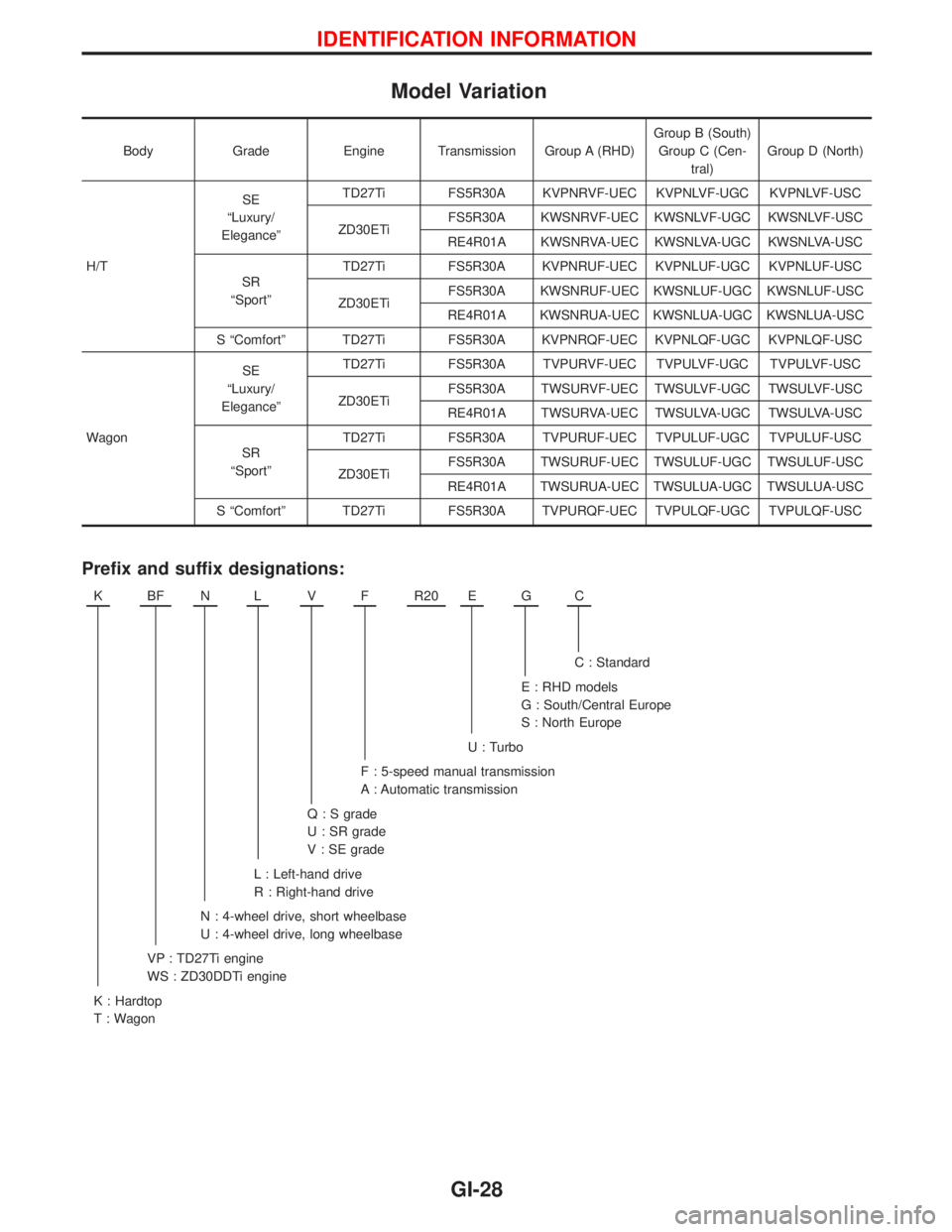
Model Variation
Body Grade Engine Transmission Group A (RHD)Group B (South)
Group C (Cen-
tral)Group D (North)
H/TSE
ªLuxury/
EleganceºTD27Ti FS5R30A KVPNRVF-UEC KVPNLVF-UGC KVPNLVF-USC
ZD30ETiFS5R30A KWSNRVF-UEC KWSNLVF-UGC KWSNLVF-USC
RE4R01A KWSNRVA-UEC KWSNLVA-UGC KWSNLVA-USC
SR
ªSportºTD27Ti FS5R30A KVPNRUF-UEC KVPNLUF-UGC KVPNLUF-USC
ZD30ETiFS5R30A KWSNRUF-UEC KWSNLUF-UGC KWSNLUF-USC
RE4R01A KWSNRUA-UEC KWSNLUA-UGC KWSNLUA-USC
S ªComfortº TD27Ti FS5R30A KVPNRQF-UEC KVPNLQF-UGC KVPNLQF-USC
WagonSE
ªLuxury/
EleganceºTD27Ti FS5R30A TVPURVF-UEC TVPULVF-UGC TVPULVF-USC
ZD30ETiFS5R30A TWSURVF-UEC TWSULVF-UGC TWSULVF-USC
RE4R01A TWSURVA-UEC TWSULVA-UGC TWSULVA-USC
SR
ªSportºTD27Ti FS5R30A TVPURUF-UEC TVPULUF-UGC TVPULUF-USC
ZD30ETiFS5R30A TWSURUF-UEC TWSULUF-UGC TWSULUF-USC
RE4R01A TWSURUA-UEC TWSULUA-UGC TWSULUA-USC
S ªComfortº TD27Ti FS5R30A TVPURQF-UEC TVPULQF-UGC TVPULQF-USC
Prefix and suffix designations:
KBFNLVFR20EGC
C : Standard
E : RHD models
G : South/Central Europe
S : North Europe
U : Turbo
F : 5-speed manual transmission
A : Automatic transmission
Q : S grade
U : SR grade
V : SE grade
L : Left-hand drive
R : Right-hand drive
N : 4-wheel drive, short wheelbase
U : 4-wheel drive, long wheelbase
VP : TD27Ti engine
WS : ZD30DDTi engine
K : Hardtop
T : Wagon
IDENTIFICATION INFORMATION
GI-28
Page 1345 of 1767
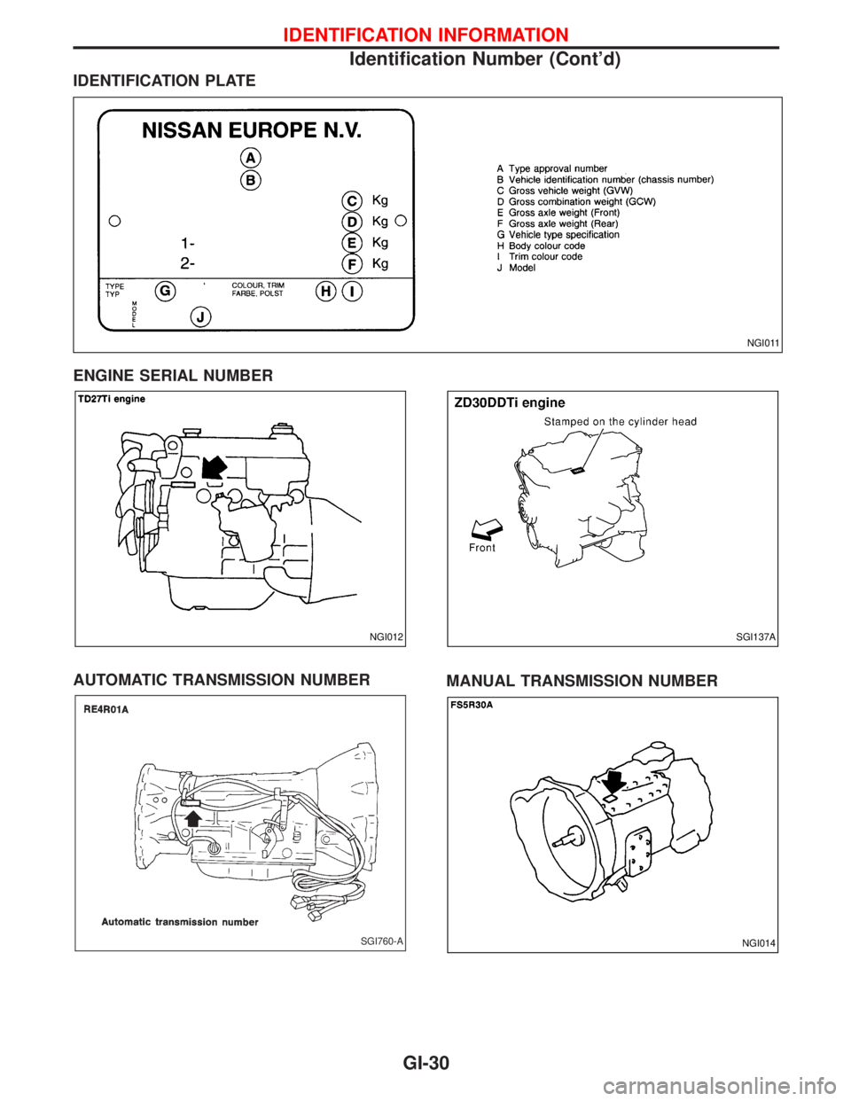
IDENTIFICATION PLATE
ENGINE SERIAL NUMBER
AUTOMATIC TRANSMISSION NUMBER
MANUAL TRANSMISSION NUMBER
NGI011
NGI012SGI137A
SGI760-ANGI014
IDENTIFICATION INFORMATION
Identification Number (Cont'd)
GI-30