relay NISSAN TERRANO 2002 Service Repair Manual
[x] Cancel search | Manufacturer: NISSAN, Model Year: 2002, Model line: TERRANO, Model: NISSAN TERRANO 2002Pages: 1767, PDF Size: 41.51 MB
Page 148 of 1767
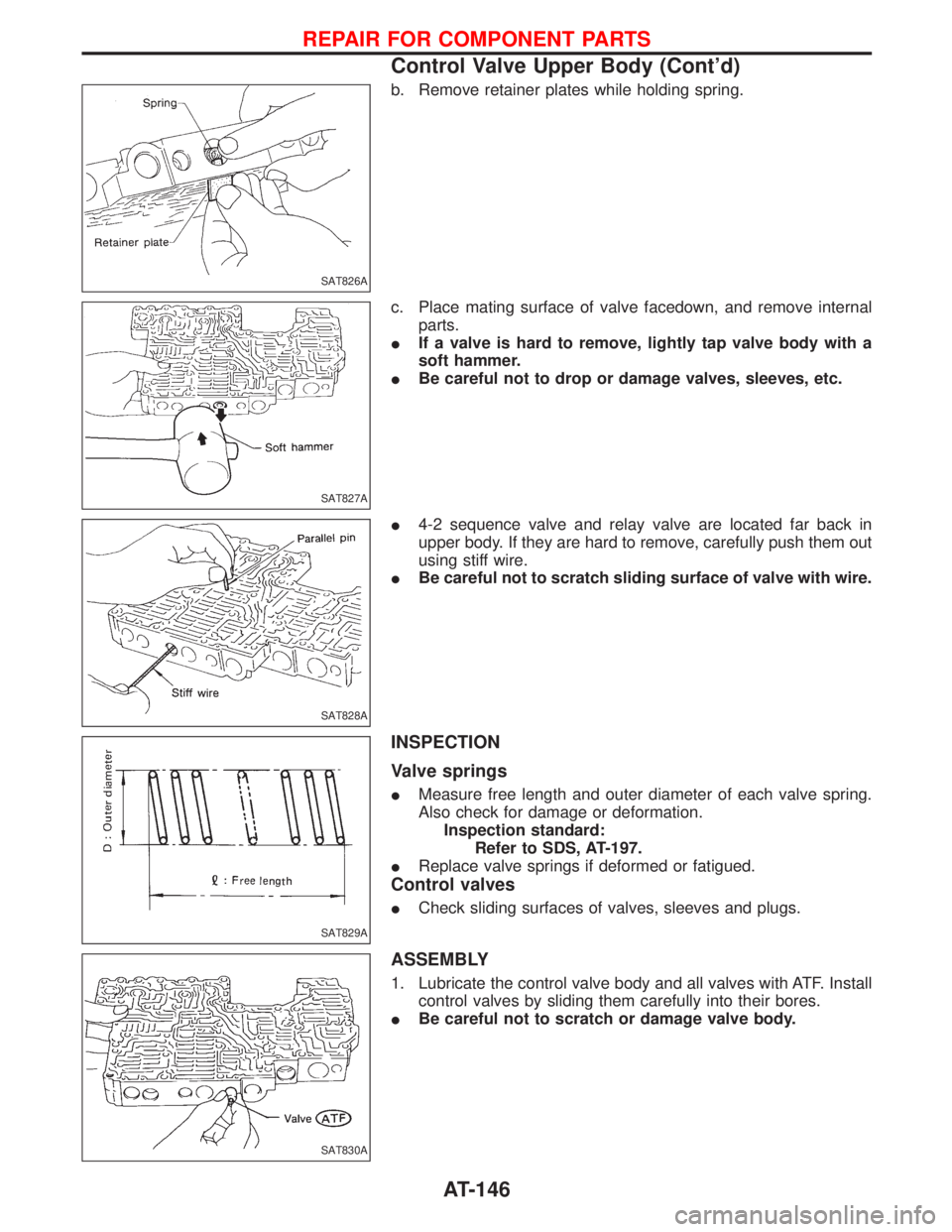
b. Remove retainer plates while holding spring.
c. Place mating surface of valve facedown, and remove internal
parts.
IIf a valve is hard to remove, lightly tap valve body with a
soft hammer.
IBe careful not to drop or damage valves, sleeves, etc.
I4-2 sequence valve and relay valve are located far back in
upper body. If they are hard to remove, carefully push them out
using stiff wire.
IBe careful not to scratch sliding surface of valve with wire.
INSPECTION
Valve springs
IMeasure free length and outer diameter of each valve spring.
Also check for damage or deformation.
Inspection standard:
Refer to SDS, AT-197.
IReplace valve springs if deformed or fatigued.
Control valves
ICheck sliding surfaces of valves, sleeves and plugs.
ASSEMBLY
1. Lubricate the control valve body and all valves with ATF. Install
control valves by sliding them carefully into their bores.
IBe careful not to scratch or damage valve body.
SAT826A
SAT827A
SAT828A
SAT829A
SAT830A
REPAIR FOR COMPONENT PARTS
Control Valve Upper Body (Cont'd)
AT-146
Page 150 of 1767
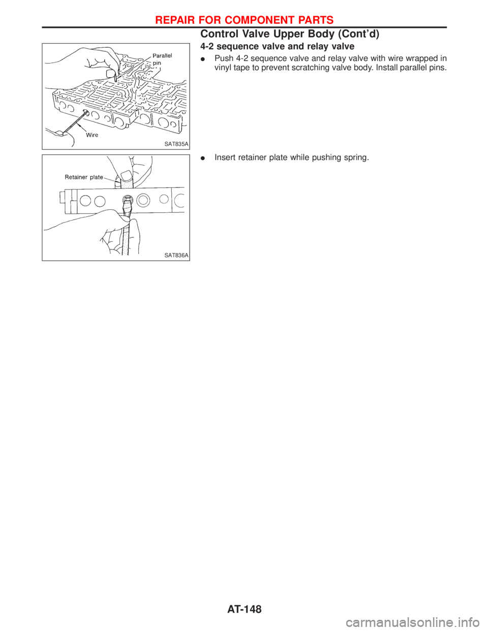
4-2 sequence valve and relay valve
IPush 4-2 sequence valve and relay valve with wire wrapped in
vinyl tape to prevent scratching valve body. Install parallel pins.
IInsert retainer plate while pushing spring.
SAT835A
SAT836A
REPAIR FOR COMPONENT PARTS
Control Valve Upper Body (Cont'd)
AT-148
Page 199 of 1767

RETURN SPRINGSUnit: mm (in)
PartsItem
Part No. Free length Outer diameter
Control
valveUpper
bodyTorque converter relief valve
springq
131742-41X23 38.0 (1.496) 9.0 (0.354)
Pressure regulator valve
springq
231742-41X24 44.02 (1.7331) 14.0 (0.551)
Pressure modifier valve
springq
331742-41X19 31.95 (1.2579) 6.8 (0.268)
Accumulator control valve
springÐÐÐÐ
Shuttle shift valve D springq
431762-41X01 25.0 (0.984) 7.0 (0.276)
4-2 sequence valve springq
531756-41X00 29.1 (1.146) 6.95 (0.2736)
Shift valve B springq
631762-41X01 25.0 (0.984) 7.0 (0.276)
4-2 relay valve springq
731756-41X00 29.1 (1.146) 6.95 (0.2736)
Shift valve A springq
831762-41X01 25.0 (0.984) 7.0 (0.276)
Overrun clutch control valve
springq
931762-41X03 23.6 (0.929) 7.0 (0.276)
Overrun clutch reducing
valve springq
1031742-41X20 32.5 (1.280) 7.0 (0.276)
Shuttle shift valve S springq
1131762-41X04 51.0 (2.008) 5.65 (0.2224)
Pilot valve springq
1231742-41X13 25.7 (1.012) 9.0 (0.354)
Torque converter clutch con-
trol valve springq
1331742-41X22 18.5 (0.728) 13.0 (0.512)
Lower
bodyModifier accumulator
piston springq
131742-27X70 31.4 (1.236) 9.8 (0.386)
1st reducing valve springq
231756-41X05 25.4 (1.000) 6.75 (0.2657)
3-2 timing valve springq
331742-41X06 23.0 (0.906) 6.7 (0.264)
Servo charger valve springq
431742-41X06 23.0 (0.906) 6.7 (0.264)
Reverse clutch 16 pcs 31521-41X02 (Assembly) 19.69 (0.7752) 11.6 (0.457)
High clutch 10 pcs 31521-41X03 (Assembly) 24.2 (0.953) 11.6 (0.457)
Forward clutch
(Overrun clutch)20 pcs 32521-41X00 (Assembly) 35.77 (1.4083) 9.7 (0.382)
Low & reverse
brake18 pcs 31655-41X00 (Assembly) 22.3 (0.878) 11.2 (0.441)
Band servoSpringq
A31605-41X05 45.6 (1.795) 34.3 (1.350)
Springq
B31605-41X00 53.8 (2.118) 40.3 (1.587)
Springq
C31605-41X01 29.7 (1.169) 27.6 (1.087)
AccumulatorAccumulatorq
A31605-41X02 43.0 (1.693) 18.0 (0.709)
Accumulatorq
B31605-41X10 66.0 (2.598) 20.0 (0.787)
Accumulatorq
C31605-41X09 45.0 (1.772) 29.3 (1.154)
Accumulatorq
D31605-41X06 58.4 (2.299) 17.3 (0.681)
ACCUMULATOR O-RING
AccumulatorDiameter mm (in)
qAqBqCqD
Small diameter end 29 (1.14) 32 (1.26) 45 (1.77) 29 (1.14)
Large diameter end 45 (1.77) 50 (1.97) 50 (1.97) 45 (1.77)
SERVICE DATA AND SPECIFICATIONS (SDS)
Specifications and Adjustment (Cont'd)
AT-197
Page 204 of 1767
Diagnostic Procedure 2 (Warning lamp stays on
when ignition switch is turned ON)............................69
Diagnostic Procedure 3 (ABS actuator solenoid
valve and solenoid valve relay) .................................71
Diagnostic Procedure 4 (Wheel sensor or rotor) ......73
Diagnostic Procedure 5 (Motor Relay or motor) .......75
Diagnostic Procedure 7 (Low voltage) ......................77
Diagnostic Procedure 8 (G sensor) ...........................78
Diagnostic Procedure 9 (Control unit) .......................79
Diagnostic Procedure 10 (Pedal vibration and
noise) .........................................................................80Diagnostic Procedure 11 (Long stopping
distance) ....................................................................80
Diagnostic Procedure 12 (Unexpected pedal
action) ........................................................................81
Diagnostic Procedure 13 ...........................................82
Diagnostic Procedure 14 ...........................................82
Electrical Components Inspection .............................83
SERVICE DATA AND SPECIFICATIONS (SDS)..........84
General Specifications ...............................................84
Inspection and Adjustment ........................................85
CONTENTS(Cont'd)
BR-2
Page 240 of 1767
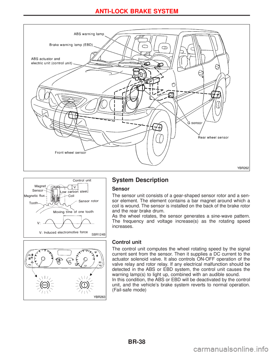
System Description
Sensor
The sensor unit consists of a gear-shaped sensor rotor and a sen-
sor element. The element contains a bar magnet around which a
coil is wound. The sensor is installed on the back of the brake rotor
and the rear brake drum.
As the wheel rotates, the sensor generates a sine-wave pattern.
The frequency and voltage increase(s) as the rotating speed
increases.
Control unit
The control unit computes the wheel rotating speed by the signal
current sent from the sensor. Then it supplies a DC current to the
actuator solenoid valve. It also controls ON-OFF operation of the
valve relay and rotor relay. If any electrical malfunction should be
detected in the ABS or EBD system, the control unit causes the
warning lamp(s) to light up, combined with an audible sound.
In this condition, the ABS or EBD will be deactivated by the control
unit, and the vehicle's brake system reverts to normal operation.
(Fail-safe mode)
YBR262
SBR124B
YBR263
ANTI-LOCK BRAKE SYSTEM
BR-38
Page 242 of 1767
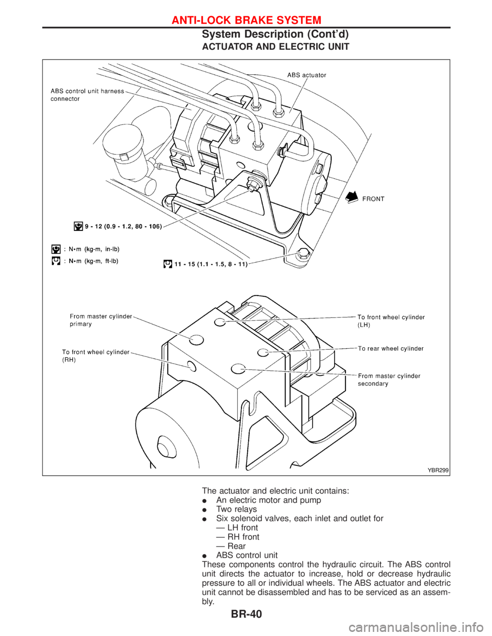
ACTUATOR AND ELECTRIC UNIT
The actuator and electric unit contains:
IAn electric motor and pump
ITwo relays
ISix solenoid valves, each inlet and outlet for
Ð LH front
Ð RH front
Ð Rear
IABS control unit
These components control the hydraulic circuit. The ABS control
unit directs the actuator to increase, hold or decrease hydraulic
pressure to all or individual wheels. The ABS actuator and electric
unit cannot be disassembled and has to be serviced as an assem-
bly.
YBR299
ANTI-LOCK BRAKE SYSTEM
System Description (Cont'd)
BR-40
Page 260 of 1767
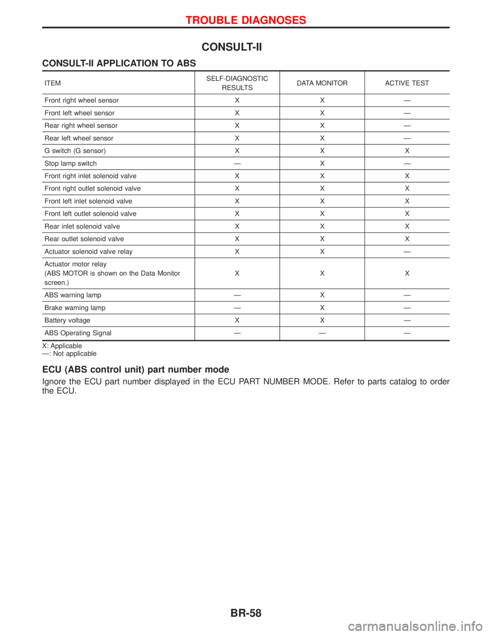
CONSULT-II
CONSULT-II APPLICATION TO ABS
ITEMSELF-DIAGNOSTIC
RESULTSDATA MONITOR ACTIVE TEST
Front right wheel sensor X X Ð
Front left wheel sensor X X Ð
Rear right wheel sensor X X Ð
Rear left wheel sensor X X Ð
G switch (G sensor) X X X
Stop lamp switch Ð X Ð
Front right inlet solenoid valve X X X
Front right outlet solenoid valve X X X
Front left inlet solenoid valve X X X
Front left outlet solenoid valve X X X
Rear inlet solenoid valve X X X
Rear outlet solenoid valve X X X
Actuator solenoid valve relay X X Ð
Actuator motor relay
(ABS MOTOR is shown on the Data Monitor
screen.)XXX
ABS warning lamp Ð X Ð
Brake warning lamp Ð X Ð
Battery voltage X X Ð
ABS Operating Signal Ð Ð Ð
X: Applicable
Ð: Not applicable
ECU (ABS control unit) part number mode
Ignore the ECU part number displayed in the ECU PART NUMBER MODE. Refer to parts catalog to order
the ECU.
TROUBLE DIAGNOSES
BR-58
Page 262 of 1767
![NISSAN TERRANO 2002 Service Repair Manual SELF-DIAGNOSTIC RESULTS MODE
Diagnostic item Diagnostic item is detected when...Diagnostic
procedure
FR RH SENSORH
[OPEN]ICircuit for front right wheel sensor is open.
(An abnormally high input voltag NISSAN TERRANO 2002 Service Repair Manual SELF-DIAGNOSTIC RESULTS MODE
Diagnostic item Diagnostic item is detected when...Diagnostic
procedure
FR RH SENSORH
[OPEN]ICircuit for front right wheel sensor is open.
(An abnormally high input voltag](/img/5/57393/w960_57393-261.png)
SELF-DIAGNOSTIC RESULTS MODE
Diagnostic item Diagnostic item is detected when...Diagnostic
procedure
FR RH SENSORH
[OPEN]ICircuit for front right wheel sensor is open.
(An abnormally high input voltage is entered.)4
FR LH SENSORH
[OPEN]ICircuit for front left wheel sensor is open.
(An abnormally high input voltage is entered.)4
RR RH SENSORH
[OPEN]ICircuit for rear right sensor is open.
(An abnormally high input voltage is entered.)4
RR LH SENSORH
[OPEN]ICircuit for rear left sensor is open.
(An abnormally high input voltage is entered.)4
FR RH SENSORH
[SHORT]ICircuit for front right wheel sensor is shorted.
(An abnormally low input voltage is entered.)4
FR LH SENSORH
[SHORT]ICircuit for front left wheel sensor is shorted.
(An abnormally low input voltage is entered.)4
RR RH SENSORH
[SHORT]ICircuit for rear right sensor is shorted.
(An abnormally low input voltage is entered.)4
RR LH SENSORH
[SHORT]ICircuit for rear left sensor is shorted.
(An abnormally low input voltage is entered.)4
ABS SENSORH
[ABNORMAL SIGNAL]ITeeth damage on sensor rotor or misalignment of wheel sensor.
(Abnormal wheel sensor signal is entered.)4
FR RH IN ABS SOL
[OPEN, SHORT]ICircuit for front right inlet solenoid valve is open or shorted.
(An abnormally low output voltage is entered.)3
FR LH IN ABS SOL
[OPEN, SHORT]ICircuit for front left inlet solenoid valve is open or shorted.
(An abnormally low output voltage is entered.)3
FR RH OUT ABS SOL
[OPEN, SHORT]ICircuit for front right outlet solenoid valve is open or shorted.
(An abnormally low output voltage is entered.)3
FR LH OUT ABS SOL
[OPEN, SHORT]ICircuit for front left outlet solenoid valve is open or shorted.
(An abnormally low output voltage is entered.)3
RR IN ABS SOL
[OPEN, SHORT]ICircuit for rear right outlet solenoid valve is open or shorted.
(An abnormally high output voltage is entered.)3
RR OUT ABS SOL
[OPEN, SHORT]ICircuit for rear left outlet solenoid valve is open or shorted.
(An abnormally high output voltage is entered.)3
ABS ACTUATOR RELAY
[ABNORMAL]IActuator solenoid valve relay is ON, even if control unit sends OFF signal.
IActuator solenoid valve relay is OFF, even if control unit sends ON signal.6
ABS MOTOR RELAY
[ABNORMAL]ICircuit for ABS motor relay is open or shorted.
ICircuit for actuator motor is open or shorted.
IActuator motor relay is stuck.5
BATTERY VOLT
[VB-LOW]IPower source voltage supplied to ABS control unit is abnormally low. 7
CONTROL UNITIFunction of calculation in ABS control unit has failed. 9
G-SENSOR
[ABNORMAL]IG sensor is open.8
HIf a tire slips on rough roads for more than 10 seconds, the ABS warning lamp may come on. In this case, the malfunctioning code
regarding the wheel sensors may be memorized. Turn off the ignition switch, restart the engine and drive the vehicle at speeds
above 30 km/h (19 MPH).
TROUBLE DIAGNOSES
CONSULT-II Inspection Procedure (Cont'd)
BR-60
Page 264 of 1767
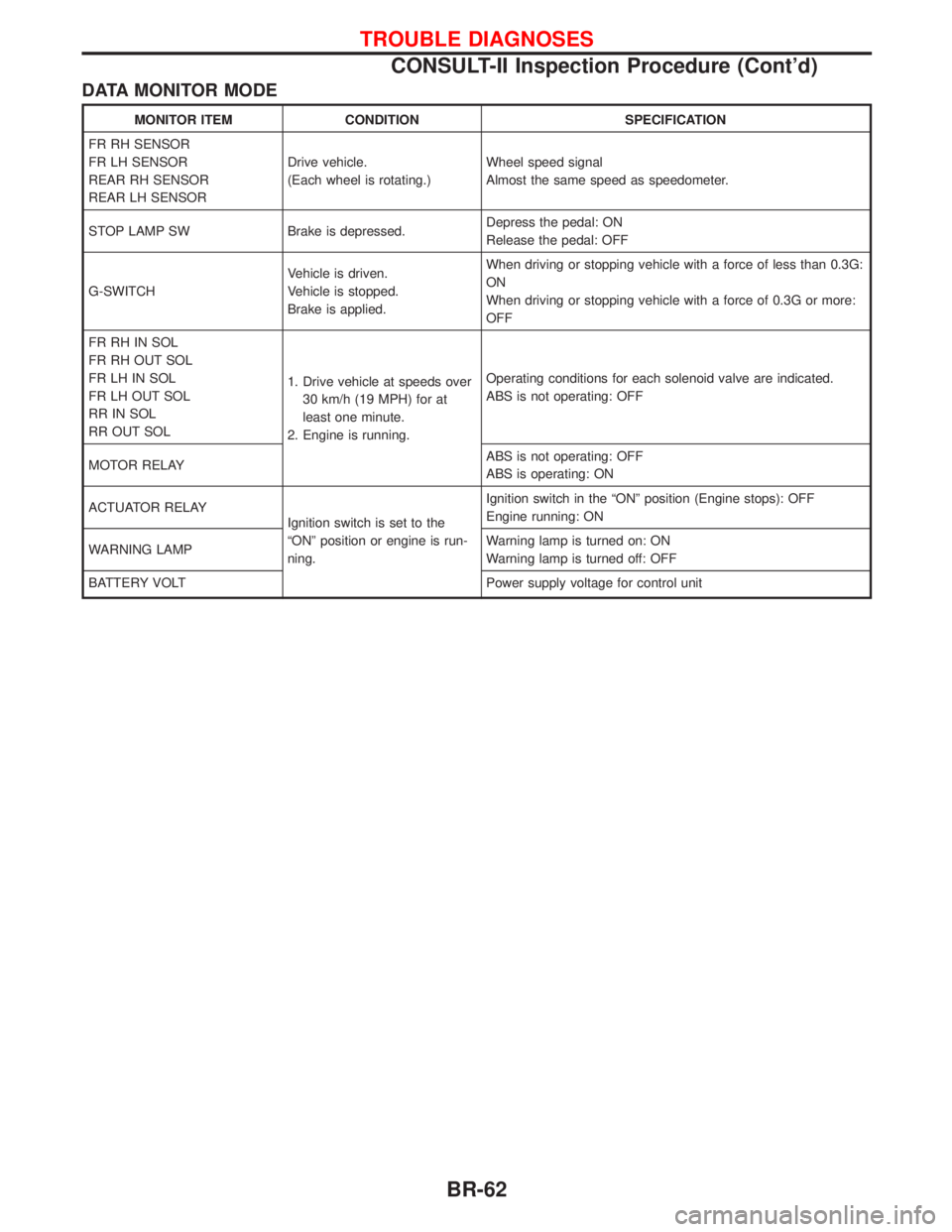
DATA MONITOR MODE
MONITOR ITEM CONDITION SPECIFICATION
FR RH SENSOR
FR LH SENSOR
REAR RH SENSOR
REAR LH SENSORDrive vehicle.
(Each wheel is rotating.)Wheel speed signal
Almost the same speed as speedometer.
STOP LAMP SW Brake is depressed.Depress the pedal: ON
Release the pedal: OFF
G-SWITCHVehicle is driven.
Vehicle is stopped.
Brake is applied.When driving or stopping vehicle with a force of less than 0.3G:
ON
When driving or stopping vehicle with a force of 0.3G or more:
OFF
FR RH IN SOL
FR RH OUT SOL
FR LH IN SOL
FR LH OUT SOL
RR IN SOL
RR OUT SOL1. Drive vehicle at speeds over
30 km/h (19 MPH) for at
least one minute.
2. Engine is running.Operating conditions for each solenoid valve are indicated.
ABS is not operating: OFF
MOTOR RELAYABS is not operating: OFF
ABS is operating: ON
ACTUATOR RELAY
Ignition switch is set to the
ªONº position or engine is run-
ning.Ignition switch in the ªONº position (Engine stops): OFF
Engine running: ON
WARNING LAMPWarning lamp is turned on: ON
Warning lamp is turned off: OFF
BATTERY VOLT Power supply voltage for control unit
TROUBLE DIAGNOSES
CONSULT-II Inspection Procedure (Cont'd)
BR-62
Page 266 of 1767
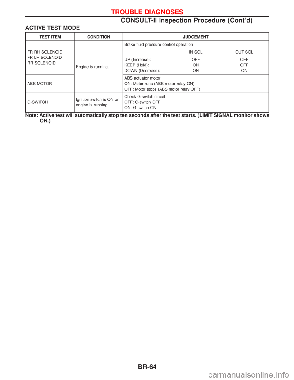
ACTIVE TEST MODE
TEST ITEM CONDITION JUDGEMENT
FR RH SOLENOID
FR LH SOLENOID
RR SOLENOID
Engine is running.Brake fluid pressure control operation
IN SOL OUT SOL
UP (Increase):
KEEP (Hold):
DOWN (Decrease):OFF
ON
ONOFF
OFF
ON
ABS MOTORABS actuator motor
ON: Motor runs (ABS motor relay ON)
OFF: Motor stops (ABS motor relay OFF)
G-SWITCHIgnition switch is ON or
engine is running.Check G-switch circuit
OFF: G-switch OFF
ON: G-switch ON
Note: Active test will automatically stop ten seconds after the test starts. (LIMIT SIGNAL monitor shows
ON.)
TROUBLE DIAGNOSES
CONSULT-II Inspection Procedure (Cont'd)
BR-64