ec-414 NISSAN TERRANO 2002 Service Repair Manual
[x] Cancel search | Manufacturer: NISSAN, Model Year: 2002, Model line: TERRANO, Model: NISSAN TERRANO 2002Pages: 1767, PDF Size: 41.51 MB
Page 655 of 1767

Alphabetical & Numerical Index for DTC
ALPHABETICAL INDEX FOR DTC
X: Applicable Ð: Not applicable
Items
(CONSULT-II screen
terms)DTC
MI illumination Reference page
CONSULT-II
GST*1ECM*2
ACCEL POS SENSOR P0120 0403 X EC-365
AIR CONDITIONR RLY P1530 0805 X EC-440
BRAKE SW P0571 0807 X EC-400
CONT SLEEV POS SEN P1207 0105 X EC-414
COOLANT TEMP SEN P0115 0103 X EC-361
CRANK POS SEN
(TDC)P0335 0407 X EC-385
ECM RLY P1620 0902 X EC-446
ECM 2 P1607 0301 X EC-444
ECM 10 P1107 0802 Ð EC-407
ECM 12 P1603 0901 X EC-444
EGR SOL/V A P1404 0806 Ð EC-431
EGR SOL/V B P1405 0808 Ð EC-431
F/INJ F/B 2 P1206 0108 X EC-409
F/INJ TIMG F/B P1246 0201 X EC-380
FUEL CUT S/V 1 P0215 0306 X EC-376
FUEL TEMP SENSOR P0180 0402 X EC-372
GLOW LAMP P0381 0908 Ð EC-389
GLOW RELAY P0380 0803 Ð EC-389
INJ TIMING CONT/V P0216 0904 X EC-380
MAS AIR FLOW SEN P0100 0102 X EC-356
MI P0650 0907 Ð EC-404
NEEDL LIFT SE (RPM) P1242 0906 X EC-427
NEEDLE LIFT SEN P1240 0304 X EC-427
NO SELF DIAGNOSTIC
FAILURE INDICATEDP0000 0505 Ð Ð
OVER HEAT P1217 0208 X EC-418
THROTTLE SOLENOID
VA LV EP1407 0808 Ð EC-431
VEHICLE SPEED SEN P0500 0104 Ð EC-397
*1: These numbers are prescribed by ISO 15031-6.
*2: In Diagnostic Test Mode II (Self-diagnostic results). These numbers are controlled by NISSAN.
TROUBLE DIAGNOSIS Ð INDEXTD27Ti
EC-293
Page 656 of 1767

NUMERICAL INDEX FOR DTC
X: Applicable Ð: Not applicable
DTC
Items
(CONSULT-II screen
terms)MI illumination Reference page
CONSULT-II
GST*1ECM*2
P0000 0505NO SELF DIAGNOSTIC
FAILURE INDICATEDÐÐ
P0100 0102 MAS AIR FLOW SEN X EC-356
P0115 0103 COOLANT TEMP SEN X EC-361
P0120 0403 ACCEL POS SENSOR X EC-365
P0180 0402 FUEL TEMP SENSOR X EC-372
P0215 0306 FUEL CUT S/V 1 X EC-376
P0216 0904 INJ TIMING CONT/V X EC-380
P0335 0407CRANK POS SEN
(TDC)X EC-385
P0380 0803 GLOW RELAY Ð EC-389
P0381 0908 GLOW LAMP Ð EC-389
P0500 0104 VEHICLE SPEED SEN Ð EC-397
P0571 0807 BRAKE SW X EC-400
P0650 0907 MI Ð EC-404
P1107 0802 ECM 10 Ð EC-407
P1206 0108 F/INJ F/B 2 X EC-409
P1207 0105 CONT SLEEV POS SEN X EC-414
P1217 0208 OVER HEAT X EC-418
P1240 0304 NEEDLE LIFT SEN X EC-427
P1242 0906 NEEDL LIFT SE(RPM) X EC-427
P1246 0201 F/INJ TIMG F/B X EC-380
P1404 0806 EGR SOL/V A Ð EC-431
P1405 0808 EGR SOL/V B Ð EC-431
P1407 0808THROTTLE SOLENOID
VA LV EÐ EC-431
P1530 0805 AIR CONDITIONR RLY X EC-440
P1603 0901 ECM 12 X EC-444
P1607 0301 ECM 2 X EC-444
P1620 0902 ECM RLY X EC-446
*1: These numbers are prescribed by ISO 15031-6.
*2: In Diagnostic Test Mode II (Self-diagnostic results). These numbers are controlled by NISSAN.
TROUBLE DIAGNOSIS Ð INDEXTD27Ti
Alphabetical & Numerical Index for DTC
(Cont'd)
EC-294
Page 703 of 1767
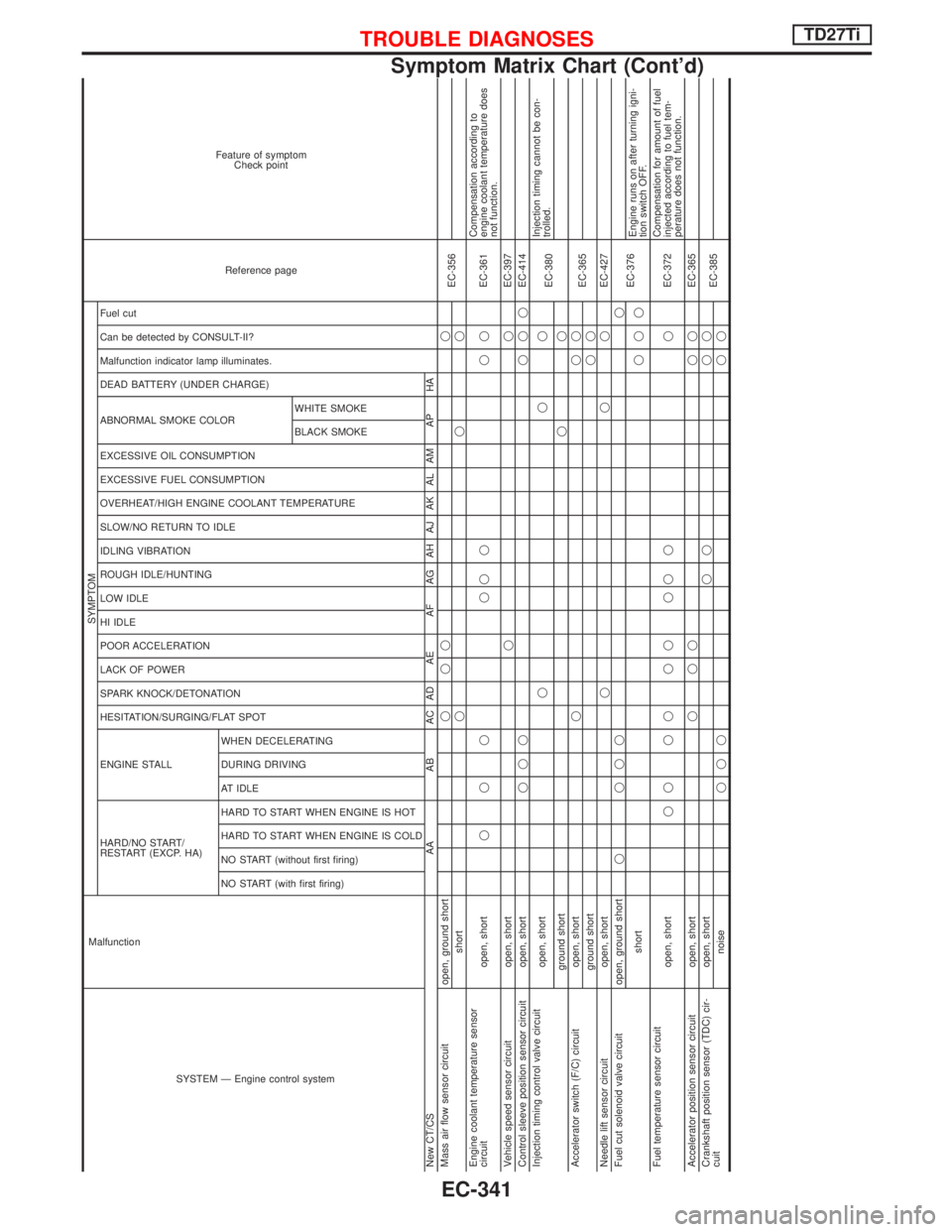
SYSTEM Ð Engine control system Malfunction
SYMPTOM
Reference page Feature of symptom
Check point
HARD/NO START/
RESTART (EXCP. HA) ENGINE STALL HESITATION/SURGING/FLAT SPOT SPARK KNOCK/DETONATION
LACK OF POWER
POOR ACCELERATION
HI IDLE
LOW IDLE
ROUGH IDLE/HUNTING
IDLING VIBRATION
SLOW/NO RETURN TO IDLE
OVERHEAT/HIGH ENGINE COOLANT TEMPERATURE
EXCESSIVE FUEL CONSUMPTION
EXCESSIVE OIL CONSUMPTION ABNORMAL SMOKE COLOR
DEAD BATTERY (UNDER CHARGE) Malfunction indicator lamp illuminates.
Can be detected by CONSULT-II?
Fuel cut
NO START (with first firing) NO START (without first firing)
HARD TO START WHEN ENGINE IS COLD
HARD TO START WHEN ENGINE IS HOT
AT IDLE
DURING DRIVING
WHEN DECELERATINGBLACK SMOKE WHITE SMOKE
New CT/CS AA AB AC AD AE AF AG AH AJ AK AL AM AP HA
Mass air flow sensor circuit open, ground shortqqq q
EC-356
shortqqq
Engine coolant temperature sensor
circuit open, shortqqq qqq qqEC-361Compensation according to
engine coolant temperature does
not function.
Vehicle speed sensor circuit open, shortqqEC-397
Control sleeve position sensor circuit open, shortqqqqqqEC-414
Injection timing control valve circuit
open, shortqqq
EC-380Injection timing cannot be con-
trolled.
ground shortqq
Accelerator switch (F/C) circuit open, shortqqq
EC-365
ground shortqq
Needle lift sensor circuit open, shortqqqEC-427
Fuel cut solenoid valve circuit open, ground shortq qqqq
EC-376
shortqqqEngine runs on after turning igni-
tion switch OFF.
Fuel temperature sensor circuit
open, shortqq qq qq qq q qEC-372Compensation for amount of fuel
injected according to fuel tem-
perature does not function.
Accelerator position sensor circuit open, shortqqq qqEC-365
Crankshaft position sensor (TDC) cir-
cuitopen, shortqq qq
EC-385
noiseqqqqq
TROUBLE DIAGNOSESTD27Ti
Symptom Matrix Chart (Cont'd)
EC-341
Page 776 of 1767
Component Description
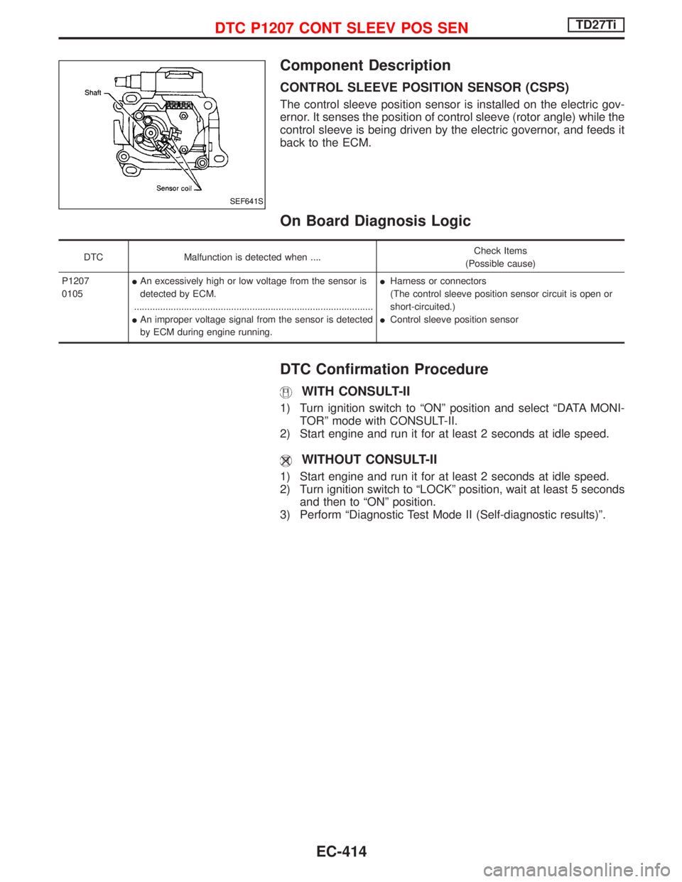
CONTROL SLEEVE POSITION SENSOR (CSPS)
The control sleeve position sensor is installed on the electric gov-
ernor. It senses the position of control sleeve (rotor angle) while the
control sleeve is being driven by the electric governor, and feeds it
back to the ECM.
On Board Diagnosis Logic
DTC Malfunction is detected when ....Check Items
(Possible cause)
P1207
0105IAn excessively high or low voltage from the sensor is
detected by ECM.
...........................................................................................
IAn improper voltage signal from the sensor is detected
by ECM during engine running.IHarness or connectors
(The control sleeve position sensor circuit is open or
short-circuited.)
IControl sleeve position sensor
DTC Confirmation Procedure
WITH CONSULT-II
1) Turn ignition switch to ªONº position and select ªDATA MONI-
TORº mode with CONSULT-II.
2) Start engine and run it for at least 2 seconds at idle speed.
WITHOUT CONSULT-II
1) Start engine and run it for at least 2 seconds at idle speed.
2) Turn ignition switch to ªLOCKº position, wait at least 5 seconds
and then to ªONº position.
3) Perform ªDiagnostic Test Mode II (Self-diagnostic results)º.
SEF641S
DTC P1207 CONT SLEEV POS SENTD27Ti
EC-414
Page 1420 of 1767
Clutch pedal .............................................CL-3, 4, 5
Clutch release mechanism ...............................CL-9
Coil spring (rear) ......................................RA-14, 16
Collision diagnosis..........................................RS-57
Combination lamp, front, removal and
installation .....................................................BT-6
Combination lamp, rear, removal and
installation .....................................................BT-8
Combination meter (needle type) ...................EL-70
Combination meter removal and instal-
lation - See Instrument panel......................BT-16
Combination switch...................................EL-23, 24
Component Location (manual A/C) ..................HA-7
Compression pressure ...................................EM-10
Compressor clutch removal and
installation ...................................................HA-24
Compressor mounting ....................................HA-21
Connecting rod...............................................EM-73
Connecting rod bearing clearance.................EM-77
Connecting rod bushing clearance ................EM-73
Console box - See Instrument panel ..............BT-16
CONSULT for ABS .........................................BR-58
CONSULT for engine .............................EC-39, 327
CONSULT-II general information.....................GI-26
Control lever (M/T) .........................................MT-13
Control lever (Transfer) .....................................TF-8
Control sleeve position sensor .....................EC-414
Control valve (A/T) ........................................AT-113
COOL/F - Wiring diagram ............................EC-112
Coolant mixture ratio ...................MA-17, 20, 22, 31
Coolant replacement ...............MA-5, 17, 20, 22, 31
Cooling circuit (engine)...............................LC-9, 27
Cooling fan ...............................................LC-15, 33
Cooling fan control .......................................EC-109
Cooling fan relay ..........................................EC-426
Corrosion protection..........................................BT-5
Counter gear (M/T) .........................................MT-11
Counter gear (Transfer) ............................TF-10, 20
Cowl top ..........................................................BT-21
Cowl top cover ................................................BT-21
Crankcase emission control system -
See positive crankcase ventilation .....EC-23, 312
Crankcase ventilation system - See
Positive crankcase ventilation ............EC-23, 312
Crankshaft ......................................................EM-76
Crankshaft position sensor (TDC) .......EC-145, 385
Cylinder block ................................................EM-66
Cylinder head .................................................EM-52
D
Data link connector ................................EC-39, 327
Daytime light system ..........................EL-29, 30, 31
DEF - Wiring diagram ...................................EL-107
Defroster door control rod adjustment ...........HA-62
Diagnosis sensor unit .....................................RS-11
Diagnostic trouble code (DTC) for OBD
system ................................................EC-33, 321
Differential carrier assembly ....................PD-29, 53Differential carrier disassembly..........PD-18, 38, 40
Differential gear oil replacement .......MA-36, 38, 39
Dimensions ......................................................GI-31
D/LOCK - Wiring diagram .............................EL-140
Door glass .......................................................BT-10
Door lock .........................................................BT-10
Door mirror ......................................................BT-48
Door trim .........................................................BT-19
Door, front .......................................................BT-10
Door, rear ........................................................BT-12
Drive belt inspection ................................MA-20, 28
Drive chain (Transfer) .....................................TF-10
Drive pinion diff. inspection ......................PD-20, 42
Drive pinion height ...................................PD-21, 49
Drive plate runout ..........................................EM-94
Drive shaft ........................................................MA-5
Drive shaft (front)..................................FA-4, 12, 22
Driver air bag..................................................RS-14
Dropping resistor (A/T)....................................AT-86
Dual pressure switch..................................HA-9, 61
E
ECM input/output signal .........................EC-69, 346
ECM relay ......................................EC-80, 209, 353
ECMRLY - Wiring diagram ...........................EC-210
ECTS - Wiring diagram ..................................EC-96
EGR control (EGRC) - solenoid valve .........EC-431
EGR control valve ........................................EC-439
EGR volume control valve ...........................EC-222
EGVC/V - Wiring diagram ............................EC-225
Electrical unit ................................................Foldout
Electronic fuel injection pump ......................EC-318
Engine compartment .......................................BT-50
Engine control circuit diagram ...............EC-16, 302
Engine control component parts
location ...............................................EC-12, 300
Engine control module (ECM) ......EC-69, 121, 200,
202, 213, 346,
407, 444
Engine control system diagram and
chart....................................................EC-17, 303
Engine coolant temperature sensor
(ECTS)................................................EC-95, 361
Engine oil filter replacement..........MA-5, 20, 21, 30
Engine oil precautions .......................................GI-6
Engine oil replacement ......................MA-20, 21, 29
Engine removal ..............................................EM-63
Engine room - See Engine
compartment ...............................................BT-50
Engine serial number ......................................GI-30
Exhaust manifold ...........................................EM-18
Exhaust system ..........................................FE-4, 10
Exhaust system inspection ............................MA-36
Extension tube diff. ..................................PD-19, 28
Exterior ............................................................BT-21
Exterior lamp.............................................EL-45, 60
ALPHABETICAL INDEX
IDX-3