transmission NISSAN TERRANO 2002 Service Repair Manual
[x] Cancel search | Manufacturer: NISSAN, Model Year: 2002, Model line: TERRANO, Model: NISSAN TERRANO 2002Pages: 1767, PDF Size: 41.51 MB
Page 1 of 1767
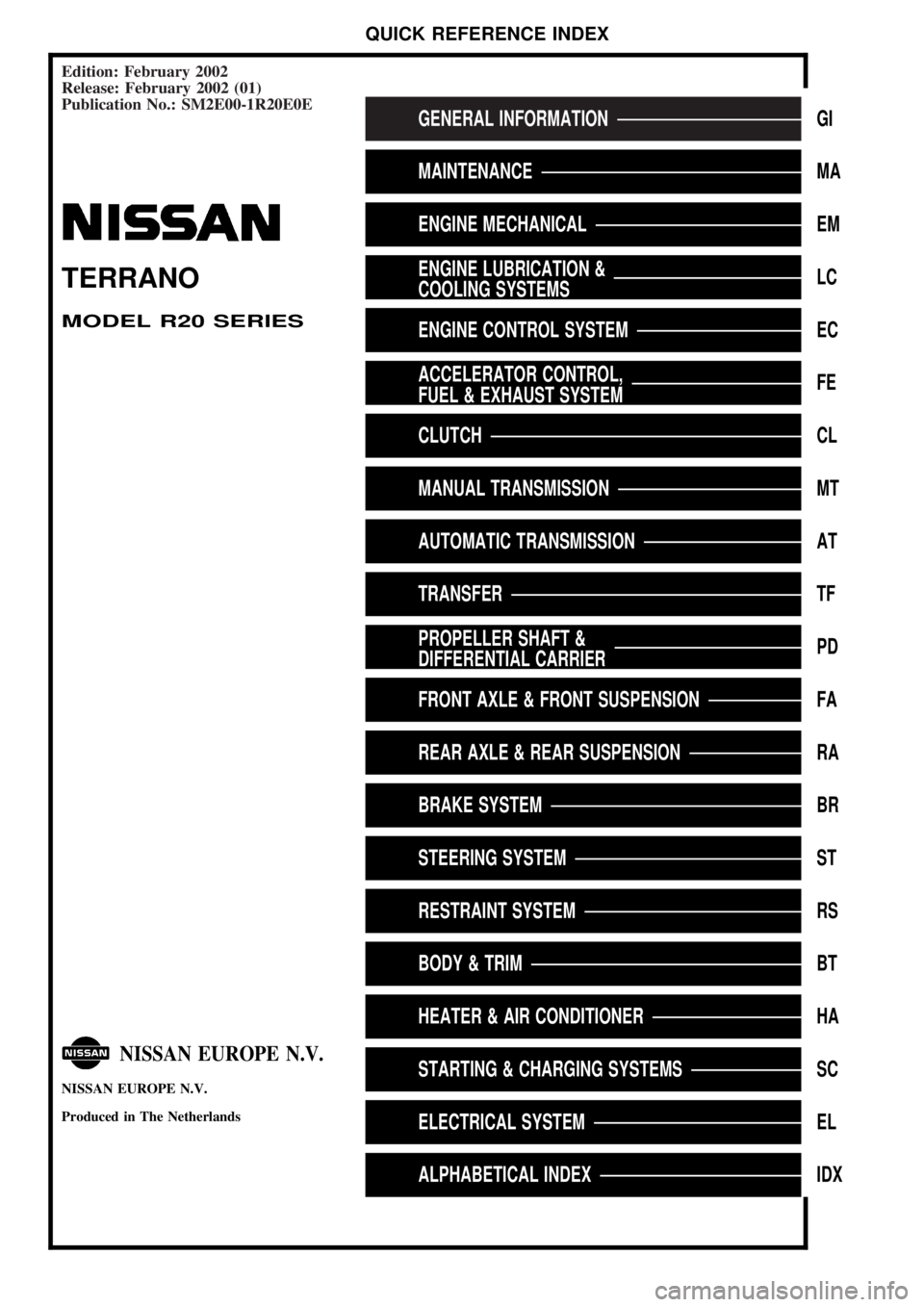
Edition: February 2002
Release: February 2002 (01)
Publication No.: SM2E00-1R20E0E
GENERAL INFORMATIONGI
MAINTENANCEMA
ENGINE MECHANICALEM
ENGINE LUBRICATION &
COOLING SYSTEMSLC
ENGINE CONTROL SYSTEMEC
ACCELERATOR CONTROL,
FUEL & EXHAUST SYSTEMFE
CLUTCHCL
MANUAL TRANSMISSIONMT
AUTOMATIC TRANSMISSIONAT
TRANSFERTF
PROPELLER SHAFT &
DIFFERENTIAL CARRIERPD
FRONT AXLE & FRONT SUSPENSIONFA
REAR AXLE & REAR SUSPENSIONRA
BRAKE SYSTEMBR
STEERING SYSTEMST
RESTRAINT SYSTEMRS
BODY & TRIMBT
HEATER & AIR CONDITIONERHA
STARTING & CHARGING SYSTEMSSC
ELECTRICAL SYSTEMEL
ALPHABETICAL INDEXIDX
TERRANO
MODEL R20 SERIES
NISSAN EUROPE N.V.
NISSAN EUROPE N.V.
Produced in The Netherlands
QUICK REFERENCE INDEX
Page 3 of 1767
AUTOMATIC TRANSMISSION
SECTION
AT
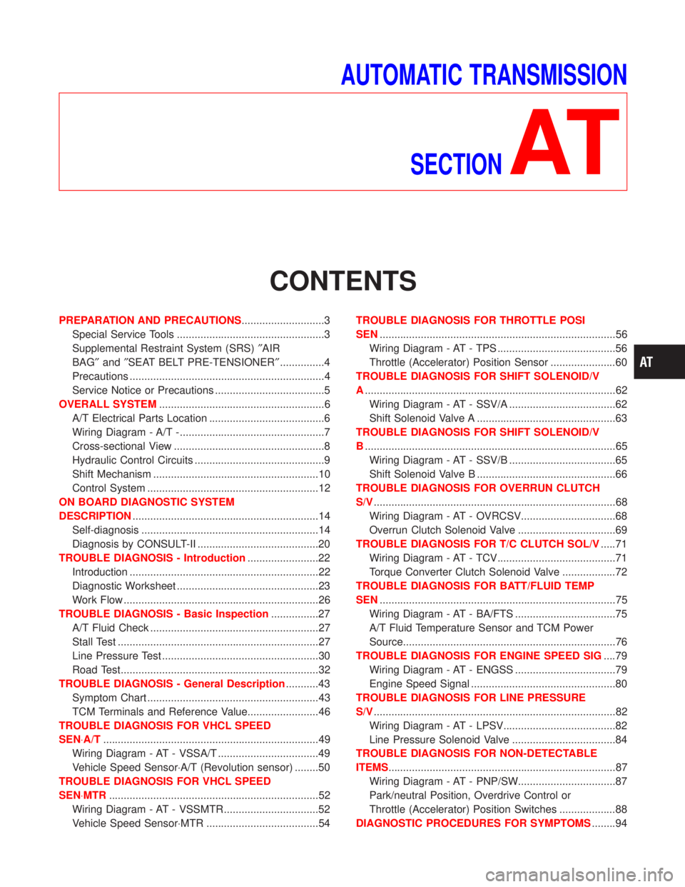
CONTENTS
PREPARATION AND PRECAUTIONS............................3
Special Service Tools ..................................................3
Supplemental Restraint System (SRS)²AIR
BAG²and²SEAT BELT PRE-TENSIONER²...............4
Precautions ..................................................................4
Service Notice or Precautions .....................................5
OVERALL SYSTEM........................................................6
A/T Electrical Parts Location .......................................6
Wiring Diagram - A/T -.................................................7
Cross-sectional View ...................................................8
Hydraulic Control Circuits ............................................9
Shift Mechanism ........................................................10
Control System ..........................................................12
ON BOARD DIAGNOSTIC SYSTEM
DESCRIPTION...............................................................14
Self-diagnosis ............................................................14
Diagnosis by CONSULT-II .........................................20
TROUBLE DIAGNOSIS - Introduction........................22
Introduction ................................................................22
Diagnostic Worksheet ................................................23
Work Flow ..................................................................26
TROUBLE DIAGNOSIS - Basic Inspection................27
A/T Fluid Check .........................................................27
Stall Test ....................................................................27
Line Pressure Test .....................................................30
Road Test...................................................................32
TROUBLE DIAGNOSIS - General Description...........43
Symptom Chart ..........................................................43
TCM Terminals and Reference Value........................46
TROUBLE DIAGNOSIS FOR VHCL SPEED
SEN×A/T.........................................................................49
Wiring Diagram - AT - VSSA/T ..................................49
Vehicle Speed Sensor×A/T (Revolution sensor) ........50
TROUBLE DIAGNOSIS FOR VHCL SPEED
SEN×MTR.......................................................................52
Wiring Diagram - AT - VSSMTR ................................52
Vehicle Speed Sensor×MTR ......................................54TROUBLE DIAGNOSIS FOR THROTTLE POSI
SEN................................................................................56
Wiring Diagram - AT - TPS ........................................56
Throttle (Accelerator) Position Sensor ......................60
TROUBLE DIAGNOSIS FOR SHIFT SOLENOID/V
A.....................................................................................62
Wiring Diagram - AT - SSV/A ....................................62
Shift Solenoid Valve A ...............................................63
TROUBLE DIAGNOSIS FOR SHIFT SOLENOID/V
B.....................................................................................65
Wiring Diagram - AT - SSV/B ....................................65
Shift Solenoid Valve B ...............................................66
TROUBLE DIAGNOSIS FOR OVERRUN CLUTCH
S/V..................................................................................68
Wiring Diagram - AT - OVRCSV................................68
Overrun Clutch Solenoid Valve .................................69
TROUBLE DIAGNOSIS FOR T/C CLUTCH SOL/V.....71
Wiring Diagram - AT - TCV........................................71
Torque Converter Clutch Solenoid Valve ..................72
TROUBLE DIAGNOSIS FOR BATT/FLUID TEMP
SEN................................................................................75
Wiring Diagram - AT - BA/FTS ..................................75
A/T Fluid Temperature Sensor and TCM Power
Source........................................................................76
TROUBLE DIAGNOSIS FOR ENGINE SPEED SIG....79
Wiring Diagram - AT - ENGSS ..................................79
Engine Speed Signal .................................................80
TROUBLE DIAGNOSIS FOR LINE PRESSURE
S/V..................................................................................82
Wiring Diagram - AT - LPSV......................................82
Line Pressure Solenoid Valve ...................................84
TROUBLE DIAGNOSIS FOR NON-DETECTABLE
ITEMS.............................................................................87
Wiring Diagram - AT - PNP/SW.................................87
Park/neutral Position, Overdrive Control or
Throttle (Accelerator) Position Switches ...................88
DIAGNOSTIC PROCEDURES FOR SYMPTOMS........94
Page 5 of 1767
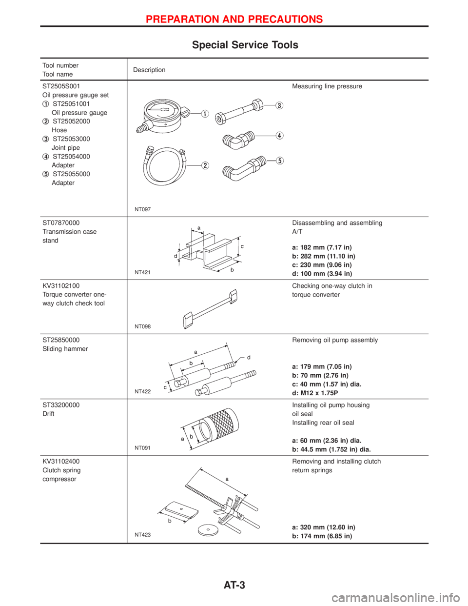
Special Service Tools
Tool number
Tool nameDescription
ST2505S001
Oil pressure gauge set
q
1ST25051001
Oil pressure gauge
q
2ST25052000
Hose
q
3ST25053000
Joint pipe
q
4ST25054000
Adapter
q
5ST25055000
Adapter
NT097
Measuring line pressure
ST07870000
Transmission case
stand
NT421
Disassembling and assembling
A/T
a: 182 mm (7.17 in)
b: 282 mm (11.10 in)
c: 230 mm (9.06 in)
d: 100 mm (3.94 in)
KV31102100
Torque converter one-
way clutch check tool
NT098
Checking one-way clutch in
torque converter
ST25850000
Sliding hammer
NT422
Removing oil pump assembly
a: 179 mm (7.05 in)
b: 70 mm (2.76 in)
c: 40 mm (1.57 in) dia.
d: M12 x 1.75P
ST33200000
Drift
NT091
Installing oil pump housing
oil seal
Installing rear oil seal
a: 60 mm (2.36 in) dia.
b: 44.5 mm (1.752 in) dia.
KV31102400
Clutch spring
compressor
NT423
Removing and installing clutch
return springs
a: 320 mm (12.60 in)
b: 174 mm (6.85 in)
PREPARATION AND PRECAUTIONS
AT- 3
Page 6 of 1767
Supplemental Restraint System (SRS) ªAIR
BAGº and ªSEAT BELT PRE-TENSIONERº
The Supplemental Restraint System such as ªAIR BAGº and ªSEAT BELT PRE-TENSIONERº used along with
a seat belt, helps to reduce the risk or severity of injury to the driver and front passenger in a frontal collision.
The SRS system composition which is available to NISSAN MODEL R20 is as follows (The composition var-
ies according to the destination.):
Driver air bag module (located in the center of the steering wheel), front passenger air bag module (located
on the instrument panel on passenger side), seat belt pre-tensioner, a diagnosis sensor unit, warning lamp,
wiring harness and spiral cable.
Information necessary to service the system safely is included in theRS sectionof this Service Manual.
WARNING:
ITo avoid rendering the SRS inoperative, which could increase the risk of personal injury or death
in the event of a collision which would result in air bag inflation, all maintenance must be performed
by an authorized NISSAN dealer.
IImproper maintenance, including incorrect removal and installation of the SRS, can lead to per-
sonal injury caused by unintentional activation of the system. For removal of Spiral Cable and Air
Bag Module, see the RS section.
IDo not use electrical test equipment on any circuit related to the SRS unless instructed to in this
Service Manual. Spiral cable and wiring harnesses covered with yellow insulation either just before
the harness connectors or for the complete harness are related to the SRS.
Precautions
IBefore proceeding with disassembly, thoroughly clean the outside of the transmission. It is important to
prevent the internal parts from becoming contaminated by dirt or other foreign matter.
IDisassembly should be done in a clean work area.
IUse lint-free cloth or towels for wiping parts clean. Common shop rags can leave fibers that could inter-
fere with the operation of the transmission.
IPlace disassembled parts in order for easier and proper assembly.
IAll parts should be carefully cleaned with a general purpose, non-flammable solvent before inspection or
reassembly.
IGaskets, seals and O-rings should be replaced any time the transmission is disassembled.
IIt is very important to perform functional tests whenever they are indicated.
IThe valve body contains precision parts and requires extreme care when parts are removed and serviced.
Place removed parts in a parts rack in order to replace them in correct positions and sequences. Care will
also prevent springs and small parts from becoming scattered or lost.
IProperly installed valves, sleeves, plugs, etc. will slide along bores in valve body under their own weight.
IBefore assembly, apply a coat of recommended ATF to all parts. Apply petroleum jelly to protect O-rings
and seals, and to hold bearings and washers in place during assembly. Do not use grease.
IExtreme care should be taken to avoid damage to O-rings, seals and gaskets when assembling.
IAfter overhaul, refill the transmission with new ATF.
IWhen the A/T drain plug is removed, only some of the fluid is drained. Old A/T fluid will remain in torque
converter and ATF cooling system.
Always follow the procedures under ªChanging A/T Fluidº in the MA section when changing A/T fluid.
PREPARATION AND PRECAUTIONS
AT- 4
Page 12 of 1767
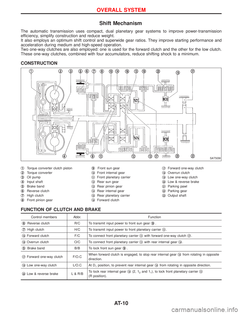
Shift Mechanism
The automatic transmission uses compact, dual planetary gear systems to improve power-transmission
efficiency, simplify construction and reduce weight.
It also employs an optimum shift control and superwide gear ratios. They improve starting performance and
acceleration during medium and high-speed operation.
Two one-way clutches are also employed: one is used for the forward clutch and the other for the low clutch.
These one-way clutches, combined with four accumulators, reduce shifting shock to a minimum.
CONSTRUCTION
q1Torque converter clutch piston
q
2Torque converter
q
3Oil pump
q
4Input shaft
q
5Brake band
q
6Reverse clutch
q
7High clutch
q
8Front pinion gearq
9Front sun gear
q
10Front internal gear
q
11Front planetary carrier
q
12Rear sun gear
q
13Rear pinion gear
q
14Rear internal gear
q
15Rear planetary carrier
q
16Forward clutchq
17Forward one-way clutch
q
18Overrun clutch
q
19Low one-way clutch
q
20Low & reverse brake
q
21Parking pawl
q
22Parking gear
q
23Output shaft
FUNCTION OF CLUTCH AND BRAKE
Control members Abbr. Function
q
6Reverse clutch R/C To transmit input power to front sun gearq9.
q
7High clutch H/C To transmit input power to front planetary carrierq11.
q
16Forward clutch F/C To connect front planetary carrierq11with forward one-way clutchq17.
q
18Overrun clutch O/C To connect front planetary carrierq11with rear internal gearq14.
q
5Brake band B/B To lock front sun gearq9.
q
17Forward one-way clutch F/O.CWhen forward clutch is engaged, to stop rear internal gearq14from rotating in opposite
direction.
q
19Low one-way clutch L/O.C At D1position, to prevent rear internal gearq14from rotating in opposite direction.
q
20Low & reverse brake L & R/BTo lock rear internal gearq14(2, 12and 11), to lock front planetary carrierq11
(R position).
SAT509I
OVERALL SYSTEM
AT-10
Page 13 of 1767
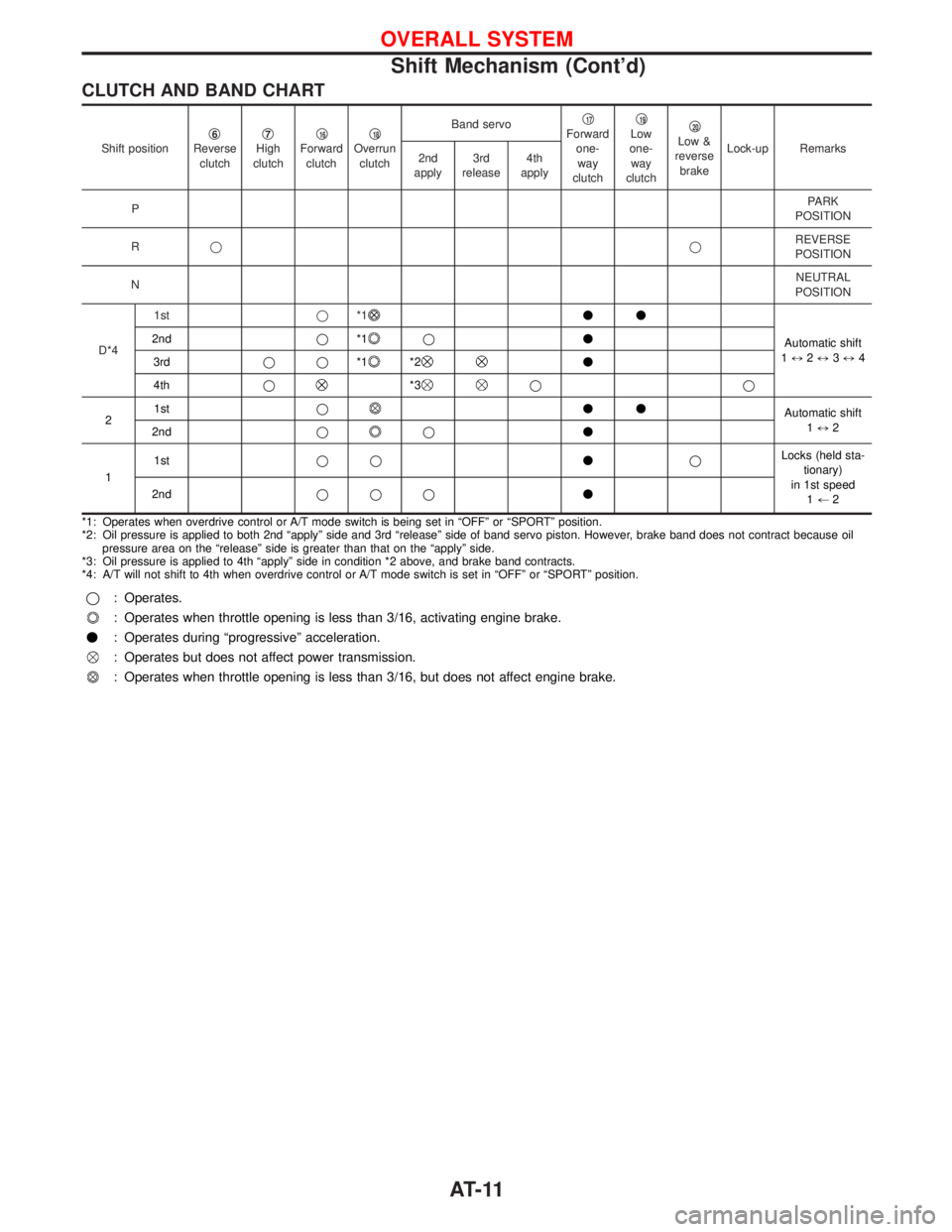
CLUTCH AND BAND CHART
Shift positionq6Reverse
clutchq7High
clutchq16Forward
clutchq18Overrun
clutchBand servoq
17Forward
one-
way
clutchq19Low
one-
way
clutchq20Low &
reverse
brakeLock-up Remarks
2nd
apply3rd
release4th
apply
PPARK
POSITION
RqqREVERSE
POSITION
NNEUTRAL
POSITION
D*41stq*1
vv
Automatic shift
1)2)3)4 2ndq*1
qv
3rdqq*1
*2v
4thq
*3qq
21stq
vv
Automatic shift
1)2
2ndq
qv
11stqqvqLocks (held sta-
tionary)
in 1st speed
1+2 2ndqqqv
*1: Operates when overdrive control or A/T mode switch is being set in ªOFFº or ªSPORTº position.
*2: Oil pressure is applied to both 2nd ªapplyº side and 3rd ªreleaseº side of band servo piston. However, brake band does not contract because oil
pressure area on the ªreleaseº side is greater than that on the ªapplyº side.
*3: Oil pressure is applied to 4th ªapplyº side in condition *2 above, and brake band contracts.
*4: A/T will not shift to 4th when overdrive control or A/T mode switch is set in ªOFFº or ªSPORTº position.
q: Operates.
: Operates when throttle opening is less than 3/16, activating engine brake.
v: Operates during ªprogressiveº acceleration.
: Operates but does not affect power transmission.
: Operates when throttle opening is less than 3/16, but does not affect engine brake.
OVERALL SYSTEM
Shift Mechanism (Cont'd)
AT-11
Page 14 of 1767
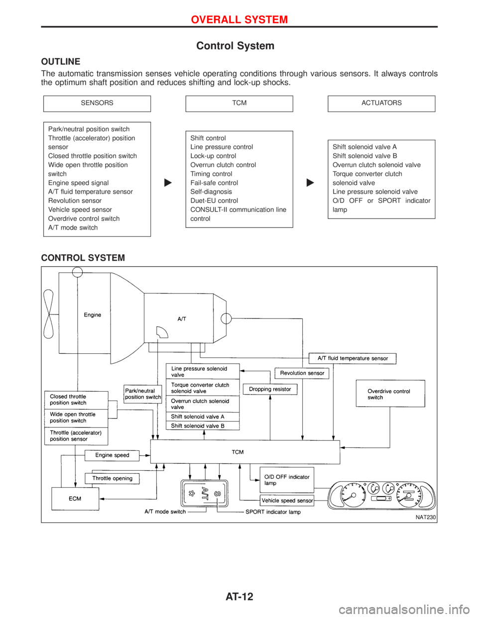
Control System
OUTLINE
The automatic transmission senses vehicle operating conditions through various sensors. It always controls
the optimum shaft position and reduces shifting and lock-up shocks.
SENSORSTCMACTUATORS
Park/neutral position switch
Throttle (accelerator) position
sensor
Closed throttle position switch
Wide open throttle position
switch
Engine speed signal
A/T fluid temperature sensor
Revolution sensor
Vehicle speed sensor
Overdrive control switch
A/T mode switch
E
Shift control
Line pressure control
Lock-up control
Overrun clutch control
Timing control
Fail-safe control
Self-diagnosis
Duet-EU control
CONSULT-II communication line
control
E
Shift solenoid valve A
Shift solenoid valve B
Overrun clutch solenoid valve
Torque converter clutch
solenoid valve
Line pressure solenoid valve
O/D OFF or SPORT indicator
lamp
CONTROL SYSTEM
NAT230
OVERALL SYSTEM
AT-12
Page 15 of 1767
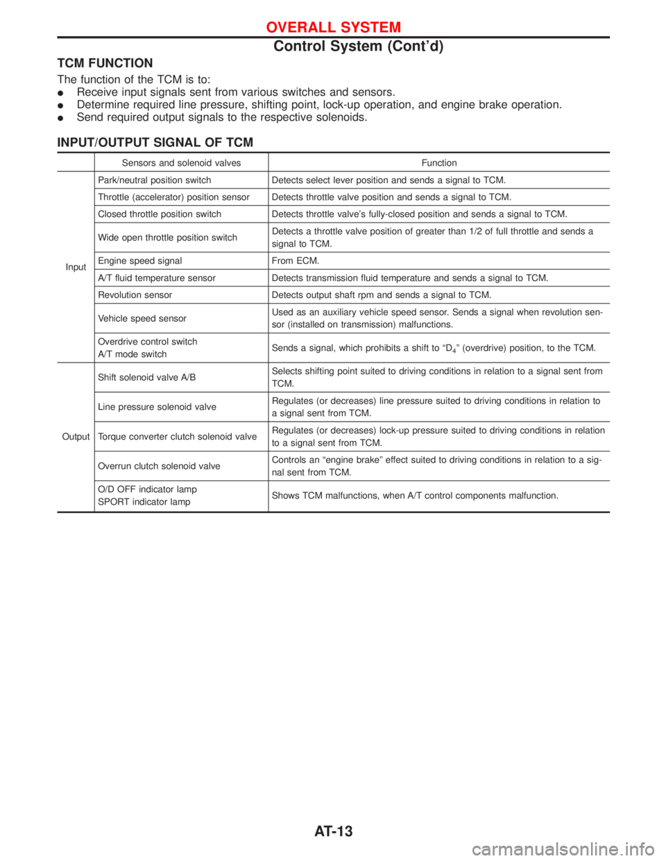
TCM FUNCTION
The function of the TCM is to:
IReceive input signals sent from various switches and sensors.
IDetermine required line pressure, shifting point, lock-up operation, and engine brake operation.
ISend required output signals to the respective solenoids.
INPUT/OUTPUT SIGNAL OF TCM
Sensors and solenoid valves Function
InputPark/neutral position switch Detects select lever position and sends a signal to TCM.
Throttle (accelerator) position sensor Detects throttle valve position and sends a signal to TCM.
Closed throttle position switch Detects throttle valve's fully-closed position and sends a signal to TCM.
Wide open throttle position switchDetects a throttle valve position of greater than 1/2 of full throttle and sends a
signal to TCM.
Engine speed signal From ECM.
A/T fluid temperature sensor Detects transmission fluid temperature and sends a signal to TCM.
Revolution sensor Detects output shaft rpm and sends a signal to TCM.
Vehicle speed sensorUsed as an auxiliary vehicle speed sensor. Sends a signal when revolution sen-
sor (installed on transmission) malfunctions.
Overdrive control switch
A/T mode switchSends a signal, which prohibits a shift to ªD
4º (overdrive) position, to the TCM.
OutputShift solenoid valve A/BSelects shifting point suited to driving conditions in relation to a signal sent from
TCM.
Line pressure solenoid valveRegulates (or decreases) line pressure suited to driving conditions in relation to
a signal sent from TCM.
Torque converter clutch solenoid valveRegulates (or decreases) lock-up pressure suited to driving conditions in relation
to a signal sent from TCM.
Overrun clutch solenoid valveControls an ªengine brakeº effect suited to driving conditions in relation to a sig-
nal sent from TCM.
O/D OFF indicator lamp
SPORT indicator lampShows TCM malfunctions, when A/T control components malfunction.
OVERALL SYSTEM
Control System (Cont'd)
AT-13
Page 29 of 1767
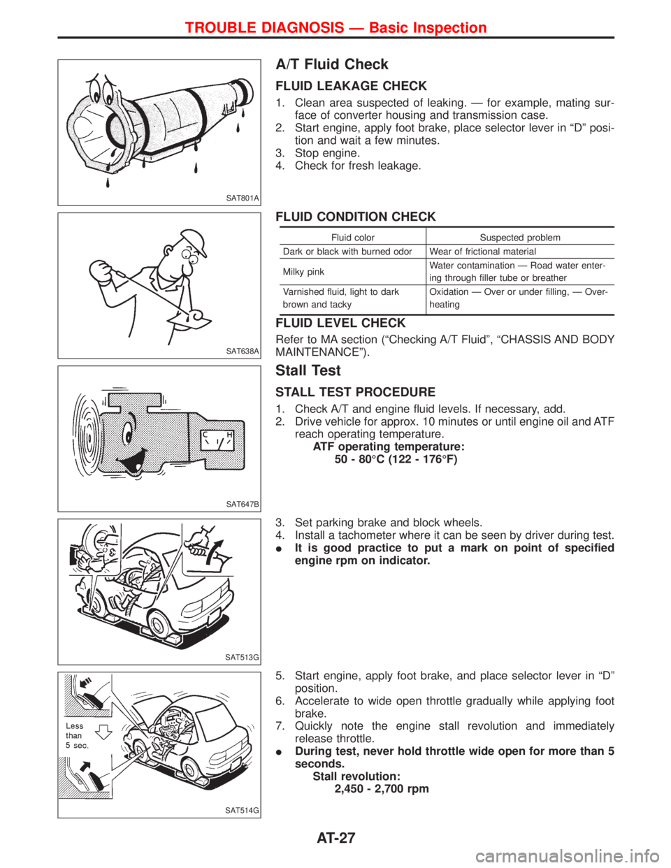
A/T Fluid Check
FLUID LEAKAGE CHECK
1. Clean area suspected of leaking. Ð for example, mating sur-
face of converter housing and transmission case.
2. Start engine, apply foot brake, place selector lever in ªDº posi-
tion and wait a few minutes.
3. Stop engine.
4. Check for fresh leakage.
FLUID CONDITION CHECK
Fluid color Suspected problem
Dark or black with burned odor Wear of frictional material
Milky pinkWater contamination Ð Road water enter-
ing through filler tube or breather
Varnished fluid, light to dark
brown and tackyOxidation Ð Over or under filling, Ð Over-
heating
FLUID LEVEL CHECK
Refer to MA section (ªChecking A/T Fluidº, ªCHASSIS AND BODY
MAINTENANCEº).
Stall Test
STALL TEST PROCEDURE
1. Check A/T and engine fluid levels. If necessary, add.
2. Drive vehicle for approx. 10 minutes or until engine oil and ATF
reach operating temperature.
ATF operating temperature:
50 - 80ÉC (122 - 176ÉF)
3. Set parking brake and block wheels.
4. Install a tachometer where it can be seen by driver during test.
IIt is good practice to put a mark on point of specified
engine rpm on indicator.
5. Start engine, apply foot brake, and place selector lever in ªDº
position.
6. Accelerate to wide open throttle gradually while applying foot
brake.
7. Quickly note the engine stall revolution and immediately
release throttle.
IDuring test, never hold throttle wide open for more than 5
seconds.
Stall revolution:
2,450 - 2,700 rpm
SAT801A
SAT638A
SAT647B
SAT513G
SAT514G
TROUBLE DIAGNOSIS Ð Basic Inspection
AT-27
Page 45 of 1767
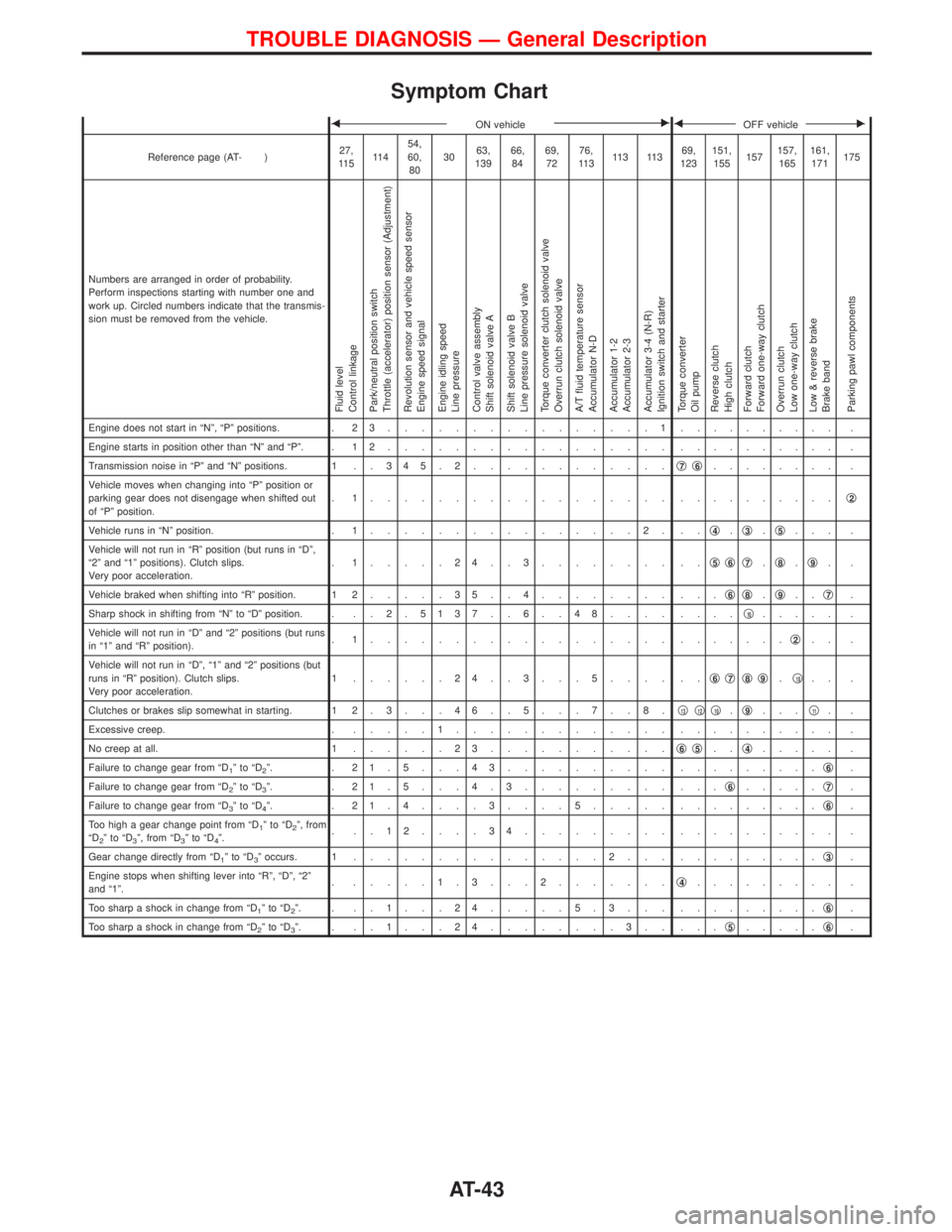
Symptom Chart
FON vehicleEFOFF vehicleE
Reference page (AT- )27,
11 511 454,
60,
803063,
13966,
8469,
7276,
11 311 3 11 369,
123151,
155157157,
165161,
171175
Numbers are arranged in order of probability.
Perform inspections starting with number one and
work up. Circled numbers indicate that the transmis-
sion must be removed from the vehicle.
Fluid level
Control linkage
Park/neutral position switch
Throttle (accelerator) position sensor (Adjustment)
Revolution sensor and vehicle speed sensor
Engine speed signal
Engine idling speed
Line pressure
Control valve assembly
Shift solenoid valve A
Shift solenoid valve B
Line pressure solenoid valve
Torque converter clutch solenoid valve
Overrun clutch solenoid valve
A/T fluid temperature sensor
Accumulator N-D
Accumulator 1-2
Accumulator 2-3
Accumulator 3-4 (N-R)
Ignition switch and starter
Torque converter
Oil pump
Reverse clutch
High clutch
Forward clutch
Forward one-way clutch
Overrun clutch
Low one-way clutch
Low & reverse brake
Brake band
Parking pawl components
Engine does not start in ªNº, ªPº positions. . 2 3................1.......... .
Engine starts in position other than ªNº and ªPº. . 1 2................. .......... .
Transmission noise in ªPº and ªNº positions. 1 . . 3 4 5 . 2............q
7q6........ .
Vehicle moves when changing into ªPº position or
parking gear does not disengage when shifted out
of ªPº position.. 1.................. ..........q
2
Vehicle runs in ªNº position. . 1................2. ..q4.q3.q5... .
Vehicle will not run in ªRº position (but runs in ªDº,
ª2º and ª1º positions). Clutch slips.
Very poor acceleration.. 1.....24..3........ ..q
5q6q7.q8.q9..
Vehicle braked when shifting into ªRº position. 1 2.....35..4........ ...q
6q8.q9..q7.
Sharp shock in shifting from ªNº to ªDº position. . . . 2 .5137 . . 6 . . 48.... ....q
10..... .
Vehicle will not run in ªDº and ª2º positions (but runs
in ª1º and ªRº position).. 1.................. .......q
2.. .
Vehicle will not run in ªDº, ª1º and ª2º positions (but
runs in ªRº position). Clutch slips.
Very poor acceleration.1 ......24..3...5.... ..q
6q7q8q9.q10.. .
Clutches or brakes slip somewhat in starting. 1 2 . 3 . . . 4 6 . . 5 . . . 7 . . 8 .q
13q12q10.q9...q11..
Excessive creep. ......1............. .......... .
No creep at all. 1......23...........q
6q5..q4..... .
Failure to change gear from ªD
1ºtoªD2º. . 21.5...43.......... .........q6.
Failure to change gear from ªD
2ºtoªD3º. . 21.5...4.3......... ...q6.....q7.
Failure to change gear from ªD
3ºtoªD4º. . 21.4....3....5..... .........q6.
Too high a gear change point from ªD
1ºtoªD2º, from
ªD2ºtoªD3º, from ªD3ºtoªD4º.. ..12....34......... .......... .
Gear change directly from ªD
1ºtoªD3º occurs. 1...............2... .........q3.
Engine stops when shifting lever into ªRº, ªDº, ª2º
and ª1º.. .....1.3...2.......q
4......... .
Too sharp a shock in change from ªD
1ºtoªD2º. . ..1...24.....5.3... .........q6.
Too sharp a shock in change from ªD
2ºtoªD3º. . ..1...24........3.. ...q5.....q6.
TROUBLE DIAGNOSIS Ð General Description
AT-43