fuse box NISSAN TERRANO 2002 Service Repair Manual
[x] Cancel search | Manufacturer: NISSAN, Model Year: 2002, Model line: TERRANO, Model: NISSAN TERRANO 2002Pages: 1767, PDF Size: 41.51 MB
Page 689 of 1767
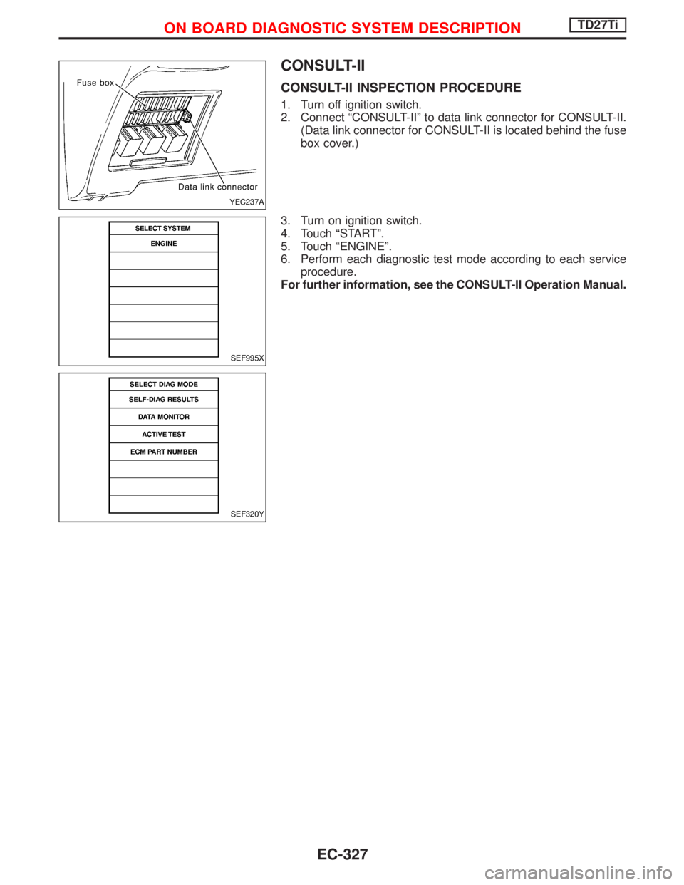
CONSULT-II
CONSULT-II INSPECTION PROCEDURE
1. Turn off ignition switch.
2. Connect ªCONSULT-IIº to data link connector for CONSULT-II.
(Data link connector for CONSULT-II is located behind the fuse
box cover.)
3. Turn on ignition switch.
4. Touch ªSTARTº.
5. Touch ªENGINEº.
6. Perform each diagnostic test mode according to each service
procedure.
For further information, see the CONSULT-II Operation Manual.
YEC237A
SEF995X
SEF320Y
ON BOARD DIAGNOSTIC SYSTEM DESCRIPTIONTD27Ti
EC-327
Page 716 of 1767
qA
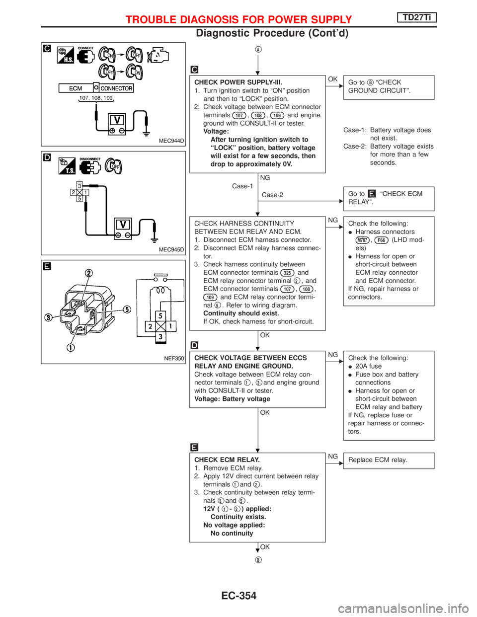
CHECK POWER SUPPLY-III.
1. Turn ignition switch to ªONº position
and then to ªLOCKº position.
2. Check voltage between ECM connector
terminals
107,108,109and engine
ground with CONSULT-II or tester.
Voltage:
After turning ignition switch to
ªLOCKº position, battery voltage
will exist for a few seconds, then
drop to approximately 0V.
NG
EOK
Go toqBªCHECK
GROUND CIRCUITº.
Case-1: Battery voltage does
not exist.
Case-2: Battery voltage exists
for more than a few
seconds.
Case-1
Case-2
EGo toªCHECK ECM
RELAYº.
CHECK HARNESS CONTINUITY
BETWEEN ECM RELAY AND ECM.
1. Disconnect ECM harness connector.
2. Disconnect ECM relay harness connec-
tor.
3. Check harness continuity between
ECM connector terminals
325and
ECM relay connector terminalq
2, and
ECM connector terminals
107,108,
109and ECM relay connector termi-
nalq
5. Refer to wiring diagram.
Continuity should exist.
If OK, check harness for short-circuit.
OK
ENG
Check the following:
IHarness connectors
M787,F66(LHD mod-
els)
IHarness for open or
short-circuit between
ECM relay connector
and ECM connector.
If NG, repair harness or
connectors.
CHECK VOLTAGE BETWEEN ECCS
RELAY AND ENGINE GROUND.
Check voltage between ECM relay con-
nector terminalsq
1,q3and engine ground
with CONSULT-II or tester.
Voltage: Battery voltage
OK
ENG
Check the following:
I20A fuse
IFuse box and battery
connections
IHarness for open or
short-circuit between
ECM relay and battery
If NG, replace fuse or
repair harness or connec-
tors.
CHECK ECM RELAY.
1. Remove ECM relay.
2. Apply 12V direct current between relay
terminalsq
1andq2.
3. Check continuity between relay termi-
nalsq
3andq5.
12V (q
1-q2) applied:
Continuity exists.
No voltage applied:
No continuity
OK
ENG
Replace ECM relay.
qB
MEC944D
MEC945D
NEF350
H
H
H
H
H
TROUBLE DIAGNOSIS FOR POWER SUPPLYTD27Ti
Diagnostic Procedure (Cont'd)
EC-354
Page 732 of 1767
qA
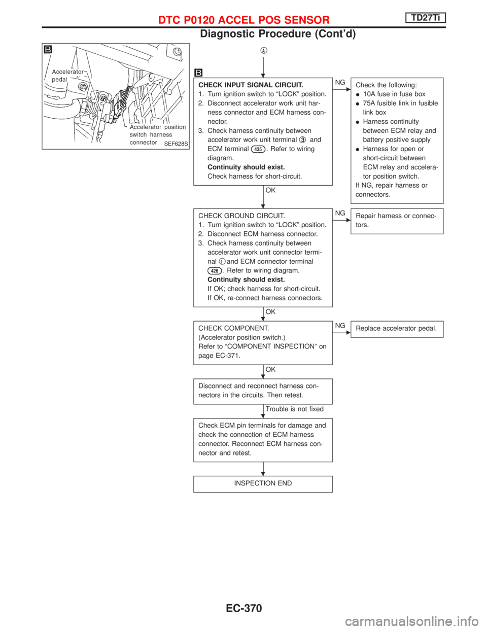
CHECK INPUT SIGNAL CIRCUIT.
1. Turn ignition switch to ªLOCKº position.
2. Disconnect accelerator work unit har-
ness connector and ECM harness con-
nector.
3. Check harness continuity between
accelerator work unit terminalq
3and
ECM terminal
435. Refer to wiring
diagram.
Continuity should exist.
Check harness for short-circuit.
OK
ENG
Check the following:
I10A fuse in fuse box
I75A fusible link in fusible
link box
IHarness continuity
between ECM relay and
battery positive supply
IHarness for open or
short-circuit between
ECM relay and accelera-
tor position switch.
If NG, repair harness or
connectors.
CHECK GROUND CIRCUIT.
1. Turn ignition switch to ªLOCKº position.
2. Disconnect ECM harness connector.
3. Check harness continuity between
accelerator work unit connector termi-
nalq
1and ECM connector terminal
426. Refer to wiring diagram.
Continuity should exist.
If OK; check harness for short-circuit.
If OK, re-connect harness connectors.
OK
ENG
Repair harness or connec-
tors.
CHECK COMPONENT.
(Accelerator position switch.)
Refer to ªCOMPONENT INSPECTIONº on
page EC-371.
OK
ENG
Replace accelerator pedal.
Disconnect and reconnect harness con-
nectors in the circuits. Then retest.
Trouble is not fixed
Check ECM pin terminals for damage and
check the connection of ECM harness
connector. Reconnect ECM harness con-
nector and retest.
INSPECTION END
SEF628S
H
H
H
H
H
H
DTC P0120 ACCEL POS SENSORTD27Ti
Diagnostic Procedure (Cont'd)
EC-370
Page 745 of 1767
Diagnostic Procedure
INSPECTION START
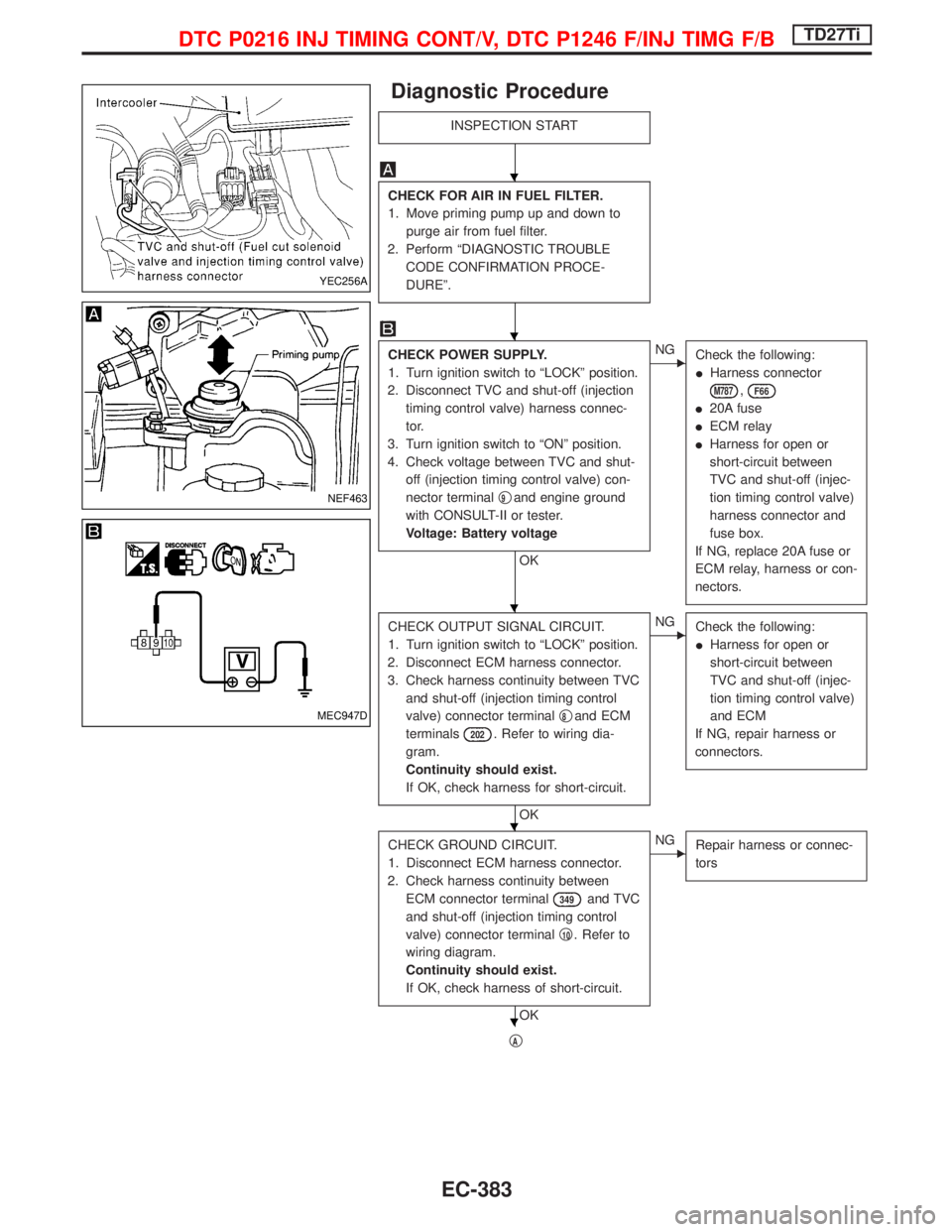
CHECK FOR AIR IN FUEL FILTER.
1. Move priming pump up and down to
purge air from fuel filter.
2. Perform ªDIAGNOSTIC TROUBLE
CODE CONFIRMATION PROCE-
DUREº.
CHECK POWER SUPPLY.
1. Turn ignition switch to ªLOCKº position.
2. Disconnect TVC and shut-off (injection
timing control valve) harness connec-
tor.
3. Turn ignition switch to ªONº position.
4. Check voltage between TVC and shut-
off (injection timing control valve) con-
nector terminalq
9and engine ground
with CONSULT-II or tester.
Voltage: Battery voltage
OK
ENG
Check the following:
IHarness connector
M787,F66
I20A fuse
IECM relay
IHarness for open or
short-circuit between
TVC and shut-off (injec-
tion timing control valve)
harness connector and
fuse box.
If NG, replace 20A fuse or
ECM relay, harness or con-
nectors.
CHECK OUTPUT SIGNAL CIRCUIT.
1. Turn ignition switch to ªLOCKº position.
2. Disconnect ECM harness connector.
3. Check harness continuity between TVC
and shut-off (injection timing control
valve) connector terminalq
8and ECM
terminals
202. Refer to wiring dia-
gram.
Continuity should exist.
If OK, check harness for short-circuit.
OK
ENG
Check the following:
IHarness for open or
short-circuit between
TVC and shut-off (injec-
tion timing control valve)
and ECM
If NG, repair harness or
connectors.
CHECK GROUND CIRCUIT.
1. Disconnect ECM harness connector.
2. Check harness continuity between
ECM connector terminal
349and TVC
and shut-off (injection timing control
valve) connector terminalq
10. Refer to
wiring diagram.
Continuity should exist.
If OK, check harness of short-circuit.
OK
ENG
Repair harness or connec-
tors
qA
YEC256A
NEF463
MEC947D
H
H
H
H
H
DTC P0216 INJ TIMING CONT/V, DTC P1246 F/INJ TIMG F/BTD27Ti
EC-383
Page 755 of 1767
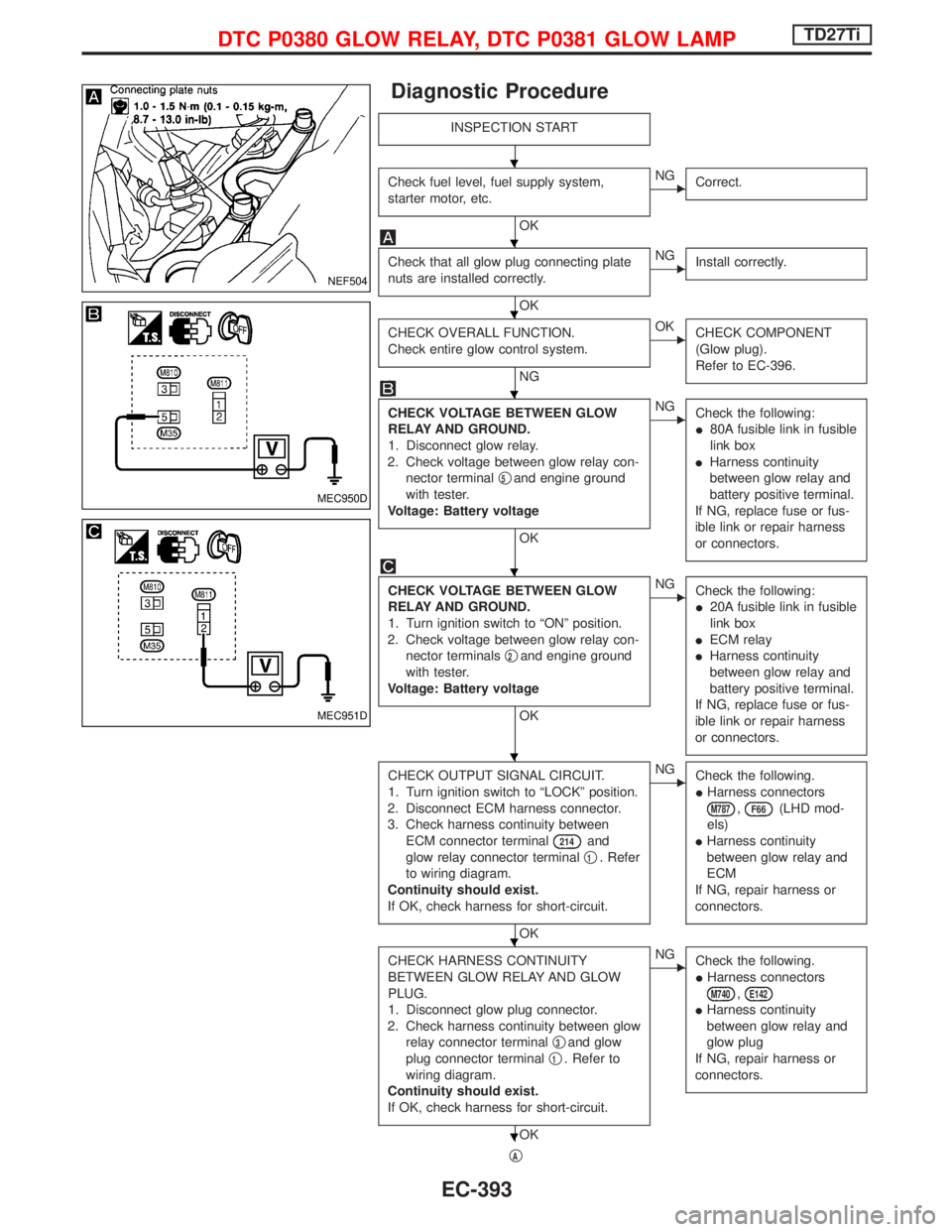
Diagnostic Procedure
INSPECTION START
Check fuel level, fuel supply system,
starter motor, etc.
OK
ENG
Correct.
Check that all glow plug connecting plate
nuts are installed correctly.
OK
ENG
Install correctly.
CHECK OVERALL FUNCTION.
Check entire glow control system.
NG
EOK
CHECK COMPONENT
(Glow plug).
Refer to EC-396.
CHECK VOLTAGE BETWEEN GLOW
RELAY AND GROUND.
1. Disconnect glow relay.
2. Check voltage between glow relay con-
nector terminalq
5and engine ground
with tester.
Voltage: Battery voltage
OK
ENG
Check the following:
I80A fusible link in fusible
link box
IHarness continuity
between glow relay and
battery positive terminal.
If NG, replace fuse or fus-
ible link or repair harness
or connectors.
CHECK VOLTAGE BETWEEN GLOW
RELAY AND GROUND.
1. Turn ignition switch to ªONº position.
2. Check voltage between glow relay con-
nector terminalsq
2and engine ground
with tester.
Voltage: Battery voltage
OK
ENG
Check the following:
I20A fusible link in fusible
link box
IECM relay
IHarness continuity
between glow relay and
battery positive terminal.
If NG, replace fuse or fus-
ible link or repair harness
or connectors.
CHECK OUTPUT SIGNAL CIRCUIT.
1. Turn ignition switch to ªLOCKº position.
2. Disconnect ECM harness connector.
3. Check harness continuity between
ECM connector terminal
214and
glow relay connector terminalq
1. Refer
to wiring diagram.
Continuity should exist.
If OK, check harness for short-circuit.
OK
ENG
Check the following.
IHarness connectors
M787,F66(LHD mod-
els)
IHarness continuity
between glow relay and
ECM
If NG, repair harness or
connectors.
CHECK HARNESS CONTINUITY
BETWEEN GLOW RELAY AND GLOW
PLUG.
1. Disconnect glow plug connector.
2. Check harness continuity between glow
relay connector terminalq
3and glow
plug connector terminalq
1. Refer to
wiring diagram.
Continuity should exist.
If OK, check harness for short-circuit.
OK
ENG
Check the following.
IHarness connectors
M740,E142
IHarness continuity
between glow relay and
glow plug
If NG, repair harness or
connectors.
qA
NEF504
MEC950D
MEC951D
H
H
H
H
H
H
H
H
DTC P0380 GLOW RELAY, DTC P0381 GLOW LAMPTD27Ti
EC-393
Page 836 of 1767
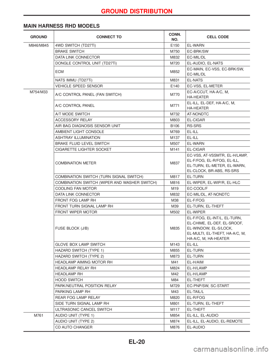
MAIN HARNESS RHD MODELS
GROUND CONNECT TOCONN.
NO.CELL CODE
M846/M845 4WD SWITCH (TD27Ti) E150 EL-WARN
BRAKE SWITCH M750 EC-BRK/SW
DATA LINK CONNECTOR M832 EC-MIL/DL
DONGLE CONTROL UNIT (TD27Ti) M720 EL-AUDIO, EL-NATS
ECM M852EC-MAIN, EC-VSS, EC-BRK/SW,
EC-MIL/DL
NATS IMMU (TD27Ti) M831 EL-NATS
VEHICLE SPEED SENSOR E140 EC-VSS, EL-METER
M754/M33
A/C CONTROL PANEL (FAN SWITCH) M770EC-A/CCUT, HA-A/C, M,
HA-HEATER
A/C CONTROL PANEL M771EL-ILL, EL-DEF, HA-A/C, M,
HA-HEATER
A/T MODE SWITCH M732 AT-NONDTC
ACCESSORY RELAY M803 EL-CIGAR
AIR BAG DIAGNOSIS SENSOR UNIT B106 RS-SRS
AMBIENT LIGHT CONSOLE M769 EL-ILL
ASHTRAY ILLUMINATION M137 EL-ILL
BRAKE FLUID LEVEL SWITCH M507 EL-WARN
CIGARETTE LIGHTER SOCKET M141 EL-CIGAR
COMBINATION METER M837EC-VSS, AT-VSSMTR, EL-H/LAMP,
EL-F/FOG, EL-R/FOG, EL-ILL,
EL-TURN, EL-METER, EL-WARN,
EL-CLOCK, BR-ABS, RS-SRS
COMBINATION SWITCH (TURN SIGNAL SWITCH) M817 EL-TURN
COMBINATION SWITCH (WIPER AND WASHER SWITCH) M816 EL-WIPER, EL-WIP/R, EL-HLC
COOLING FAN MOTOR M19 EC-COOL/F
DATA LINK CONNECTOR M832 EC-MIL/DL, AT-NONDTC
FRONT FOG LAMP RH M38 EL-F/FOG
FRONT TURN SIGNAL LAMP RH M39 EL-TURN, EL-THEFT
FRONT WIPER MOTOR M502 EL-WIPER
FUSE BLOCK (J/B) M835EL-F/FOG, EL-INT/L, EL-TURN,
EL-CHIME, EL-DEF, EL-SROOF,
EL-WINDOW, EL-S/LOCK,
EL-MULTI, EL-THEFT, HA-A/C, M,
HA-A/C, M, HA-HEATER
GLOVE BOX LAMP SWITCH M143 EL-ILL
HAZARD SWITCH (TYPE 1) M855 EL-TURN
HAZARD SWITCH (TYPE 2) M873 EL-TURN
HEADLAMP AIMING MOTOR RH M41 EL-H/AIM
HEADLAMP RELAY RH M824 EL-H/LAMP
HEADLAMP RH M42 EL-H/LAMP
HOOD SWITCH M84 EL-THEFT
PARK/NEUTRAL POSITION RELAY M729 EC-PNP/SW, SC-START
PARKING LAMP RH M43 EL-TAIL/L
REAR FOG LAMP RELAY M820 EL-R/FOG
SIDE TURN SIGNAL LAMP RH M801 EL-TURN, EL-THEFT
ULTRASONIC CANCEL SWITCH M117 EL-THEFT
M761 AUDIO UNIT (TYPE 1) M854 EL-ILL, EL-AUDIO
AUDIO UNIT (TYPE 2) M874 EL-ILL, EL-AUDIO, EL-REMOTE
CD AUTO CHANGER M876 EL-AUDIO
GROUND DISTRIBUTION
EL-20
Page 940 of 1767
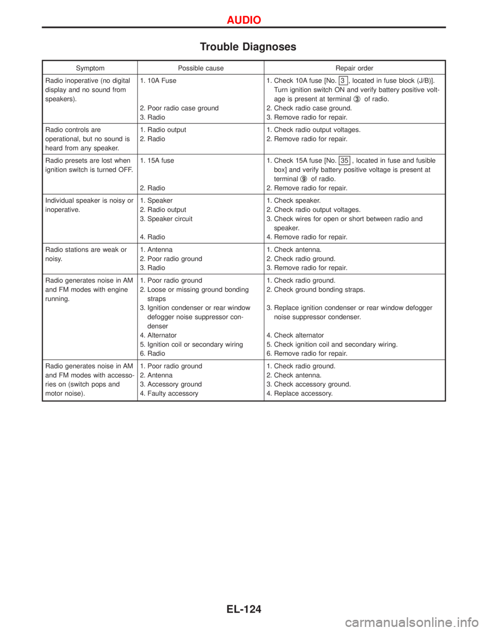
Trouble Diagnoses
Symptom Possible cause Repair order
Radio inoperative (no digital
display and no sound from
speakers).1. 10A Fuse
2. Poor radio case ground
3. Radio1. Check 10A fuse [No.
3 , located in fuse block (J/B)].
Turn ignition switch ON and verify battery positive volt-
age is present at terminalq
3of radio.
2. Check radio case ground.
3. Remove radio for repair.
Radio controls are
operational, but no sound is
heard from any speaker.1. Radio output
2. Radio1. Check radio output voltages.
2. Remove radio for repair.
Radio presets are lost when
ignition switch is turned OFF.1. 15A fuse
2. Radio1. Check 15A fuse [No.
35 , located in fuse and fusible
box] and verify battery positive voltage is present at
terminalq
9of radio.
2. Remove radio for repair.
Individual speaker is noisy or
inoperative.1. Speaker
2. Radio output
3. Speaker circuit
4. Radio1. Check speaker.
2. Check radio output voltages.
3. Check wires for open or short between radio and
speaker.
4. Remove radio for repair.
Radio stations are weak or
noisy.1. Antenna
2. Poor radio ground
3. Radio1. Check antenna.
2. Check radio ground.
3. Remove radio for repair.
Radio generates noise in AM
and FM modes with engine
running.1. Poor radio ground
2. Loose or missing ground bonding
straps
3. Ignition condenser or rear window
defogger noise suppressor con-
denser
4. Alternator
5. Ignition coil or secondary wiring
6. Radio1. Check radio ground.
2. Check ground bonding straps.
3. Replace ignition condenser or rear window defogger
noise suppressor condenser.
4. Check alternator
5. Check ignition coil and secondary wiring.
6. Remove radio for repair.
Radio generates noise in AM
and FM modes with accesso-
ries on (switch pops and
motor noise).1. Poor radio ground
2. Antenna
3. Accessory ground
4. Faulty accessory1. Check radio ground.
2. Check antenna.
3. Check accessory ground.
4. Replace accessory.
AUDIO
EL-124
Page 1055 of 1767
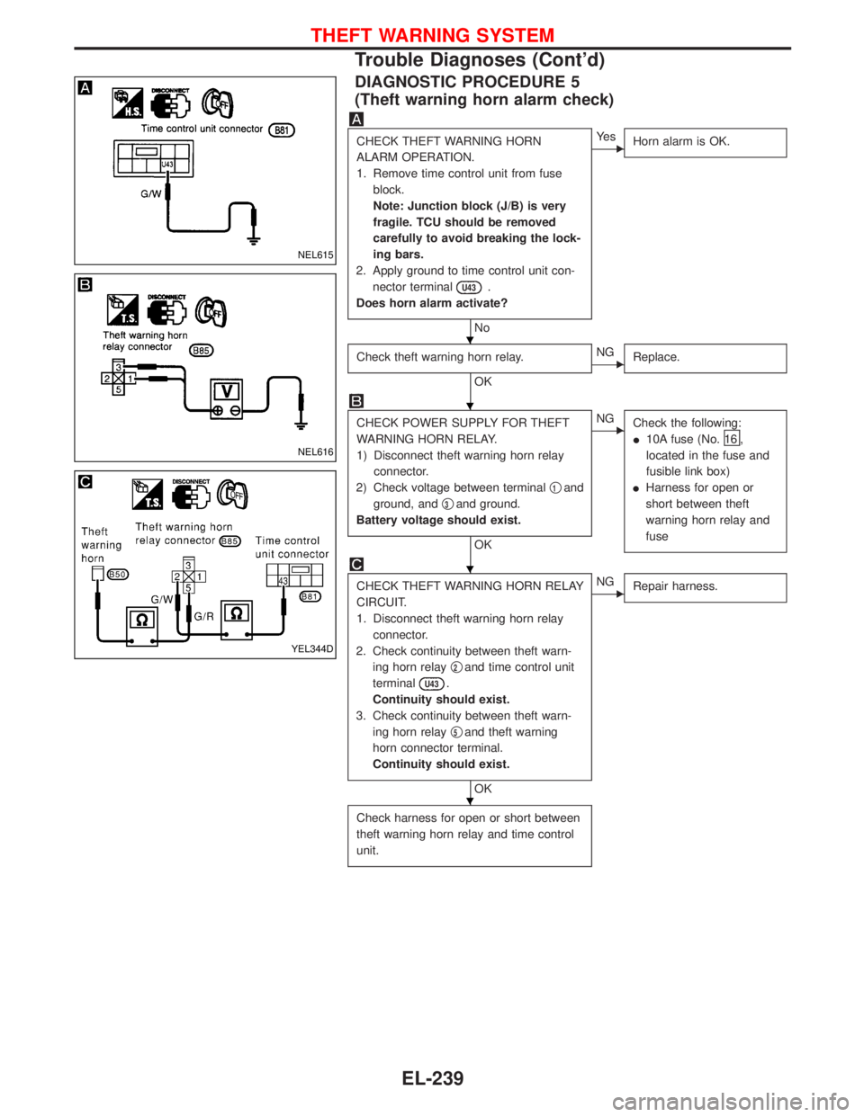
DIAGNOSTIC PROCEDURE 5
(Theft warning horn alarm check)
CHECK THEFT WARNING HORN
ALARM OPERATION.
1. Remove time control unit from fuse
block.
Note: Junction block (J/B) is very
fragile. TCU should be removed
carefully to avoid breaking the lock-
ing bars.
2. Apply ground to time control unit con-
nector terminal
U43.
Does horn alarm activate?
No
EYe s
Horn alarm is OK.
Check theft warning horn relay.
OK
ENG
Replace.
CHECK POWER SUPPLY FOR THEFT
WARNING HORN RELAY.
1) Disconnect theft warning horn relay
connector.
2) Check voltage between terminalq
1and
ground, andq
3and ground.
Battery voltage should exist.
OK
ENG
Check the following:
I10A fuse (No.
16 ,
located in the fuse and
fusible link box)
IHarness for open or
short between theft
warning horn relay and
fuse
CHECK THEFT WARNING HORN RELAY
CIRCUIT.
1. Disconnect theft warning horn relay
connector.
2. Check continuity between theft warn-
ing horn relayq
2and time control unit
terminal
U43.
Continuity should exist.
3. Check continuity between theft warn-
ing horn relayq
5and theft warning
horn connector terminal.
Continuity should exist.
OK
ENG
Repair harness.
Check harness for open or short between
theft warning horn relay and time control
unit.
NEL615
NEL616
YEL344D
H
H
H
H
THEFT WARNING SYSTEM
Trouble Diagnoses (Cont'd)
EL-239
Page 1118 of 1767
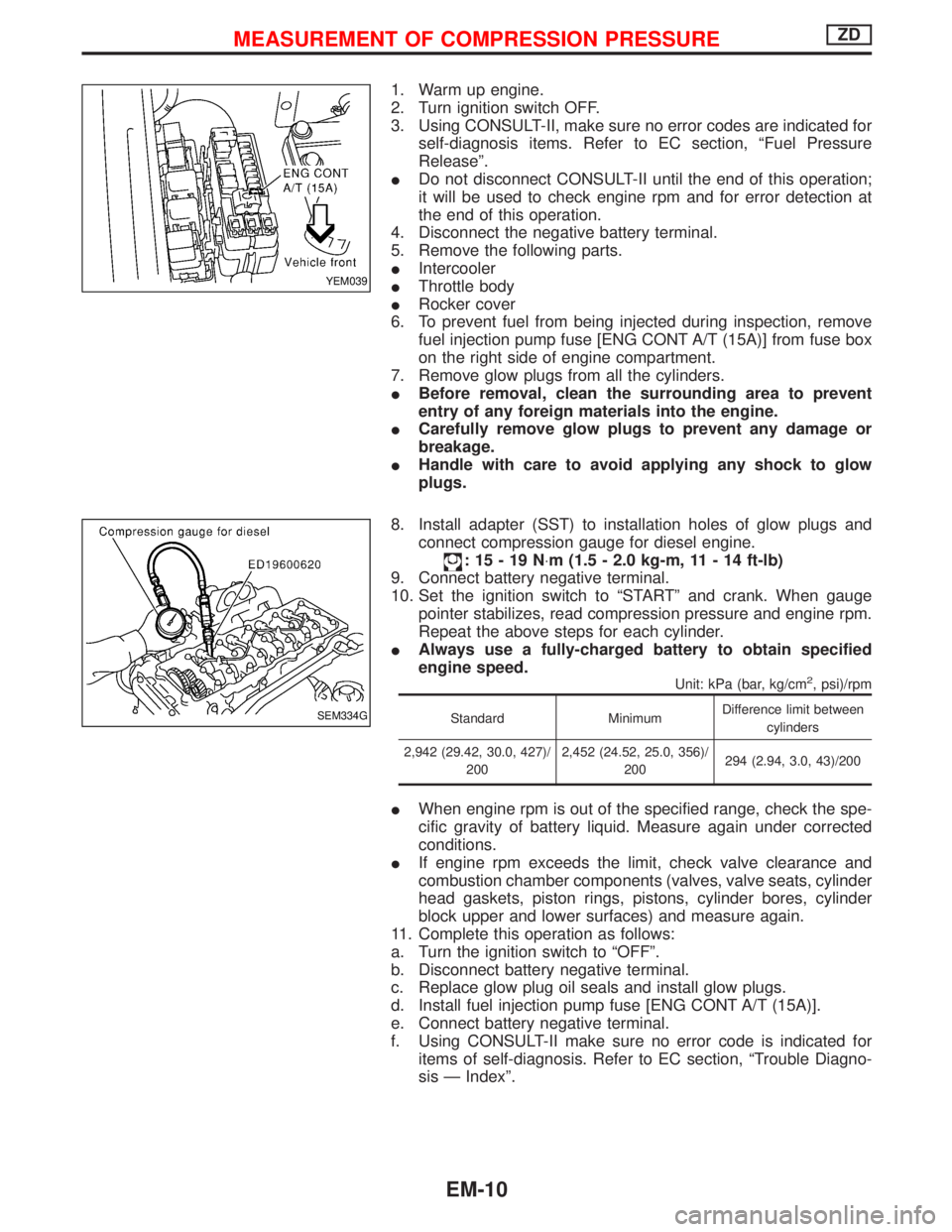
1. Warm up engine.
2. Turn ignition switch OFF.
3. Using CONSULT-II, make sure no error codes are indicated for
self-diagnosis items. Refer to EC section, ªFuel Pressure
Releaseº.
IDo not disconnect CONSULT-II until the end of this operation;
it will be used to check engine rpm and for error detection at
the end of this operation.
4. Disconnect the negative battery terminal.
5. Remove the following parts.
IIntercooler
IThrottle body
IRocker cover
6. To prevent fuel from being injected during inspection, remove
fuel injection pump fuse [ENG CONT A/T (15A)] from fuse box
on the right side of engine compartment.
7. Remove glow plugs from all the cylinders.
IBefore removal, clean the surrounding area to prevent
entry of any foreign materials into the engine.
ICarefully remove glow plugs to prevent any damage or
breakage.
IHandle with care to avoid applying any shock to glow
plugs.
8. Install adapter (SST) to installation holes of glow plugs and
connect compression gauge for diesel engine.
:15-19N×m (1.5 - 2.0 kg-m, 11 - 14 ft-lb)
9. Connect battery negative terminal.
10. Set the ignition switch to ªSTARTº and crank. When gauge
pointer stabilizes, read compression pressure and engine rpm.
Repeat the above steps for each cylinder.
IAlways use a fully-charged battery to obtain specified
engine speed.
Unit: kPa (bar, kg/cm2, psi)/rpm
Standard MinimumDifference limit between
cylinders
2,942 (29.42, 30.0, 427)/
2002,452 (24.52, 25.0, 356)/
200294 (2.94, 3.0, 43)/200
IWhen engine rpm is out of the specified range, check the spe-
cific gravity of battery liquid. Measure again under corrected
conditions.
IIf engine rpm exceeds the limit, check valve clearance and
combustion chamber components (valves, valve seats, cylinder
head gaskets, piston rings, pistons, cylinder bores, cylinder
block upper and lower surfaces) and measure again.
11. Complete this operation as follows:
a. Turn the ignition switch to ªOFFº.
b. Disconnect battery negative terminal.
c. Replace glow plug oil seals and install glow plugs.
d. Install fuel injection pump fuse [ENG CONT A/T (15A)].
e. Connect battery negative terminal.
f. Using CONSULT-II make sure no error code is indicated for
items of self-diagnosis. Refer to EC section, ªTrouble Diagno-
sis Ð Indexº.
YEM039
SEM334G
MEASUREMENT OF COMPRESSION PRESSUREZD
EM-10
Page 1313 of 1767

Terminal Arrangement
YEL275D
FUSE BLOCK Ð JUNCTION BOX (J/B)