lighting system NISSAN TERRANO 2002 Service Repair Manual
[x] Cancel search | Manufacturer: NISSAN, Model Year: 2002, Model line: TERRANO, Model: NISSAN TERRANO 2002Pages: 1767, PDF Size: 41.51 MB
Page 845 of 1767
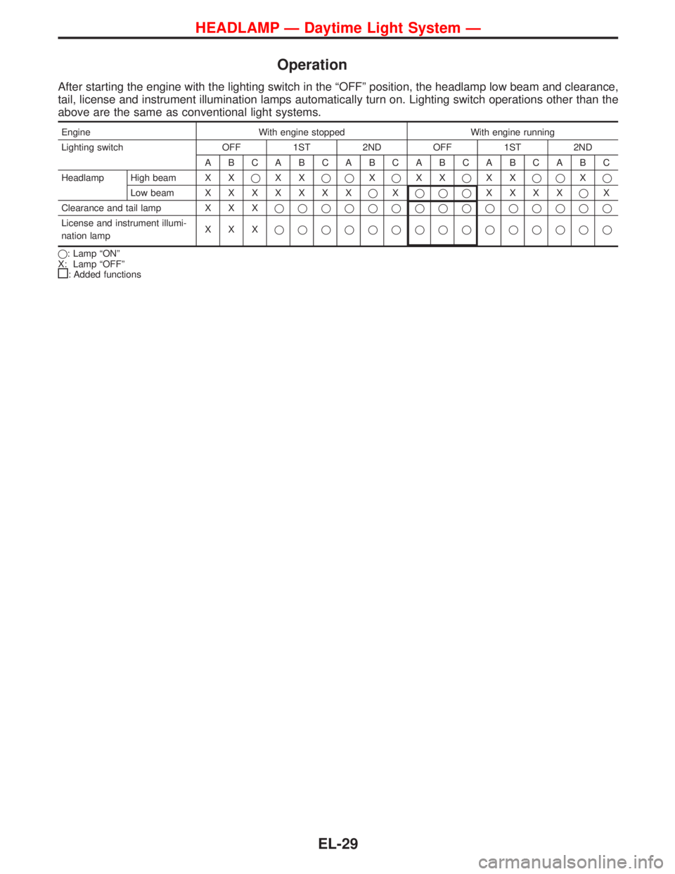
Operation
After starting the engine with the lighting switch in the ªOFFº position, the headlamp low beam and clearance,
tail, license and instrument illumination lamps automatically turn on. Lighting switch operations other than the
above are the same as conventional light systems.
Engine With engine stopped With engine running
Lighting switch OFF 1ST 2ND OFF 1ST 2ND
ABCABCABCABCABCABC
Headlamp High beam X XqXXqqXqXXqXXqqXq
Low beamXXXXXXXqXqqqXXXXqX
Clearance and tail lamp X X Xqqqqqqqqqqqqqqq
License and instrument illumi-
nation lampXXXqqqqqqqqqqqqqqq
q: Lamp ªONº
X: Lamp ªOFFº
: Added functions
HEADLAMP Ð Daytime Light System Ð
EL-29
Page 996 of 1767
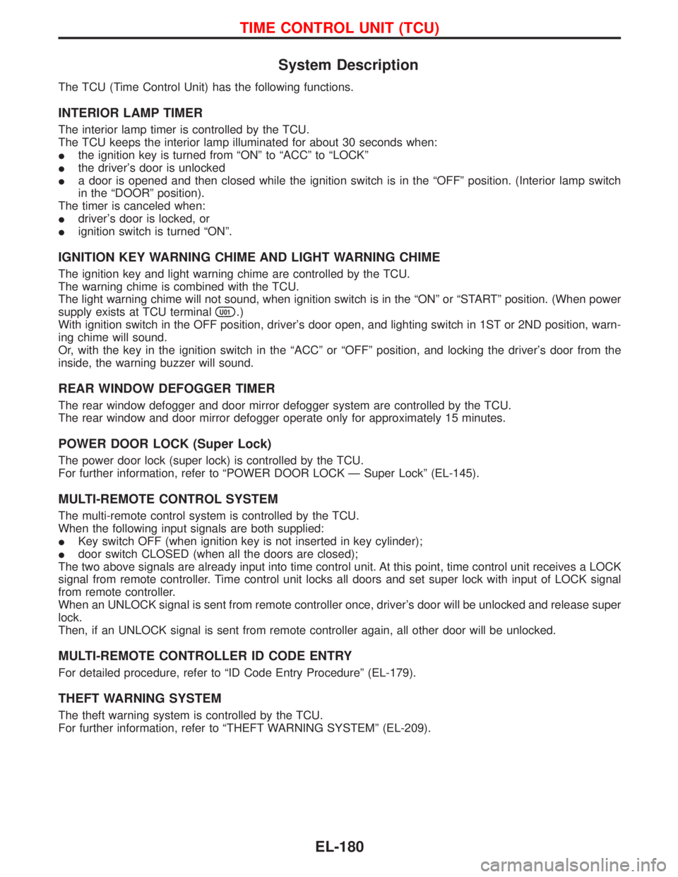
System Description
The TCU (Time Control Unit) has the following functions.
INTERIOR LAMP TIMER
The interior lamp timer is controlled by the TCU.
The TCU keeps the interior lamp illuminated for about 30 seconds when:
Ithe ignition key is turned from ªONº to ªACCº to ªLOCKº
Ithe driver's door is unlocked
Ia door is opened and then closed while the ignition switch is in the ªOFFº position. (Interior lamp switch
in the ªDOORº position).
The timer is canceled when:
Idriver's door is locked, or
Iignition switch is turned ªONº.
IGNITION KEY WARNING CHIME AND LIGHT WARNING CHIME
The ignition key and light warning chime are controlled by the TCU.
The warning chime is combined with the TCU.
The light warning chime will not sound, when ignition switch is in the ªONº or ªSTARTº position. (When power
supply exists at TCU terminal
U01.)
With ignition switch in the OFF position, driver's door open, and lighting switch in 1ST or 2ND position, warn-
ing chime will sound.
Or, with the key in the ignition switch in the ªACCº or ªOFFº position, and locking the driver's door from the
inside, the warning buzzer will sound.
REAR WINDOW DEFOGGER TIMER
The rear window defogger and door mirror defogger system are controlled by the TCU.
The rear window and door mirror defogger operate only for approximately 15 minutes.
POWER DOOR LOCK (Super Lock)
The power door lock (super lock) is controlled by the TCU.
For further information, refer to ªPOWER DOOR LOCK Ð Super Lockº (EL-145).
MULTI-REMOTE CONTROL SYSTEM
The multi-remote control system is controlled by the TCU.
When the following input signals are both supplied:
IKey switch OFF (when ignition key is not inserted in key cylinder);
Idoor switch CLOSED (when all the doors are closed);
The two above signals are already input into time control unit. At this point, time control unit receives a LOCK
signal from remote controller. Time control unit locks all doors and set super lock with input of LOCK signal
from remote controller.
When an UNLOCK signal is sent from remote controller once, driver's door will be unlocked and release super
lock.
Then, if an UNLOCK signal is sent from remote controller again, all other door will be unlocked.
MULTI-REMOTE CONTROLLER ID CODE ENTRY
For detailed procedure, refer to ªID Code Entry Procedureº (EL-179).
THEFT WARNING SYSTEM
The theft warning system is controlled by the TCU.
For further information, refer to ªTHEFT WARNING SYSTEMº (EL-209).
TIME CONTROL UNIT (TCU)
EL-180
Page 999 of 1767
Checks
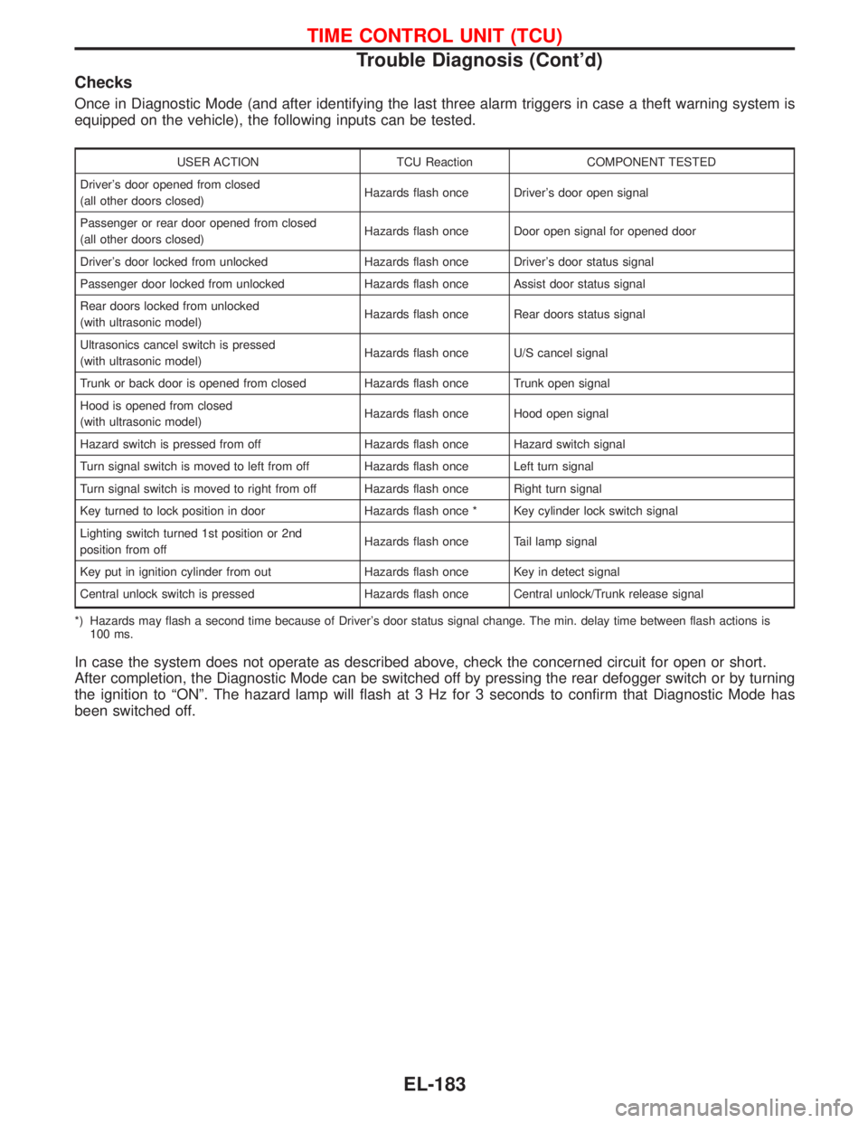
Once in Diagnostic Mode (and after identifying the last three alarm triggers in case a theft warning system is
equipped on the vehicle), the following inputs can be tested.
USER ACTION TCU Reaction COMPONENT TESTED
Driver's door opened from closed
(all other doors closed)Hazards flash once Driver's door open signal
Passenger or rear door opened from closed
(all other doors closed)Hazards flash once Door open signal for opened door
Driver's door locked from unlocked Hazards flash once Driver's door status signal
Passenger door locked from unlocked Hazards flash once Assist door status signal
Rear doors locked from unlocked
(with ultrasonic model)Hazards flash once Rear doors status signal
Ultrasonics cancel switch is pressed
(with ultrasonic model)Hazards flash once U/S cancel signal
Trunk or back door is opened from closed Hazards flash once Trunk open signal
Hood is opened from closed
(with ultrasonic model)Hazards flash once Hood open signal
Hazard switch is pressed from off Hazards flash once Hazard switch signal
Turn signal switch is moved to left from off Hazards flash once Left turn signal
Turn signal switch is moved to right from off Hazards flash once Right turn signal
Key turned to lock position in door Hazards flash once * Key cylinder lock switch signal
Lighting switch turned 1st position or 2nd
position from offHazards flash once Tail lamp signal
Key put in ignition cylinder from out Hazards flash once Key in detect signal
Central unlock switch is pressed Hazards flash once Central unlock/Trunk release signal
*) Hazards may flash a second time because of Driver's door status signal change. The min. delay time between flash actions is
100 ms.
In case the system does not operate as described above, check the concerned circuit for open or short.
After completion, the Diagnostic Mode can be switched off by pressing the rear defogger switch or by turning
the ignition to ªONº. The hazard lamp will flash at 3 Hz for 3 seconds to confirm that Diagnostic Mode has
been switched off.
TIME CONTROL UNIT (TCU)
Trouble Diagnosis (Cont'd)
EL-183
Page 1002 of 1767
System Description
NATS has the following immobiliser functions:
IThis version of NATS has dongle control unit to improve its anti-theft performance (RHD models). Dongle
control unit has its own ID which is registered into NATS IMMU. So if dongle unit is replaced, initialization
must be carried out.
IWhen malfunction of dongle unit is detected:
The security indicator lamp illuminates for about 15 minutes after ignition switch is turned to ON.
Ð When dongle control unit has a malfunction, and the indicator lamp is illuminated, engine can not be
started. However engine can be started only one time when security indicator lamp turns off in about
15 minutes after ignition switch is turned to ON.
ISince only NATS ignition keys, whose ID nos. have been registered into the ECM and IMMU of NATS,
allow the engine to run, operation of a stolen vehicle without a NATS registered key is prevented by NATS.
That is to say, NATS will immobilize the engine if someone tries to start it without the registered key of
NATS.
IAll of the originally supplied ignition key IDs have been NATS registered.
If requested by the vehicle owner, a maximum of five key IDs can be registered into the NATS compo-
nents.
IThe NATS security indicator (NATS security ind.) blinks when the ignition switch is in ªOFFº or ªACCº
position. Therefore, NATS warns outsiders that the vehicle is equipped with the anti-theft system.
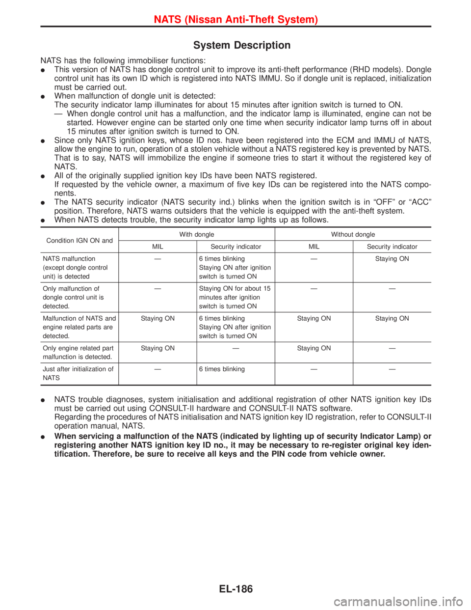
IWhen NATS detects trouble, the security indicator lamp lights up as follows.
Condition IGN ON andWith dongle Without dongle
MIL Security indicator MIL Security indicator
NATS malfunction
(except dongle control
unit) is detectedÐ 6 times blinking
Staying ON after ignition
switch is turned ONÐ Staying ON
Only malfunction of
dongle control unit is
detected.Ð Staying ON for about 15
minutes after ignition
switch is turned ONÐÐ
Malfunction of NATS and
engine related parts are
detected.Staying ON 6 times blinking
Staying ON after ignition
switch is turned ONStaying ON Staying ON
Only engine related part
malfunction is detected.Staying ON Ð Staying ON Ð
Just after initialization of
NATSÐ 6 times blinking Ð Ð
INATS trouble diagnoses, system initialisation and additional registration of other NATS ignition key IDs
must be carried out using CONSULT-II hardware and CONSULT-II NATS software.
Regarding the procedures of NATS initialisation and NATS ignition key ID registration, refer to CONSULT-II
operation manual, NATS.
IWhen servicing a malfunction of the NATS (indicated by lighting up of security Indicator Lamp) or
registering another NATS ignition key ID no., it may be necessary to re-register original key iden-
tification. Therefore, be sure to receive all keys and the PIN code from vehicle owner.
NATS (Nissan Anti-Theft System)
EL-186
Page 1011 of 1767
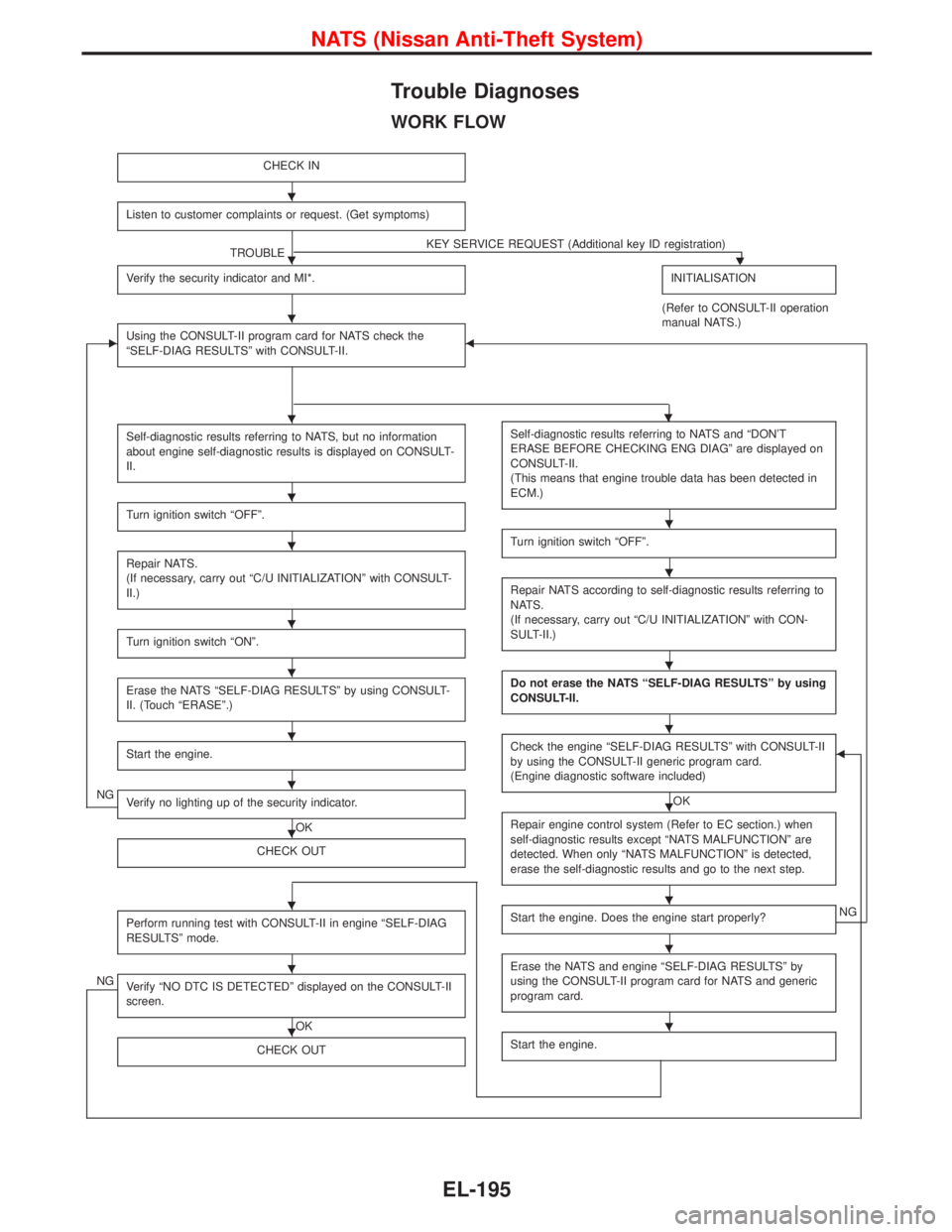
Trouble Diagnoses
WORK FLOW
CHECK IN
Listen to customer complaints or request. (Get symptoms)
TROUBLEKEY SERVICE REQUEST (Additional key ID registration)H
Verify the security indicator and MI*.INITIALISATION
(Refer to CONSULT-II operation
manual NATS.)
EUsing the CONSULT-II program card for NATS check the
ªSELF-DIAG RESULTSº with CONSULT-II.F
Self-diagnostic results referring to NATS, but no information
about engine self-diagnostic results is displayed on CONSULT-
II.
Turn ignition switch ªOFFº.
Repair NATS.
(If necessary, carry out ªC/U INITIALIZATIONº with CONSULT-
II.)
Turn ignition switch ªONº.
Erase the NATS ªSELF-DIAG RESULTSº by using CONSULT-
II. (Touch ªERASEº.)
Start the engine.
NGVerify no lighting up of the security indicator.
OK
CHECK OUT
Perform running test with CONSULT-II in engine ªSELF-DIAG
RESULTSº mode.
NGVerify ªNO DTC IS DETECTEDº displayed on the CONSULT-II
screen.
OK
CHECK OUT
Self-diagnostic results referring to NATS and ªDON'T
ERASE BEFORE CHECKING ENG DIAGº are displayed on
CONSULT-II.
(This means that engine trouble data has been detected in
ECM.)
Turn ignition switch ªOFFº.
Repair NATS according to self-diagnostic results referring to
NATS.
(If necessary, carry out ªC/U INITIALIZATIONº with CON-
SULT-II.)
Do not erase the NATS ªSELF-DIAG RESULTSº by using
CONSULT-II.
Check the engine ªSELF-DIAG RESULTSº with CONSULT-II
by using the CONSULT-II generic program card.
(Engine diagnostic software included)
OK
F
Repair engine control system (Refer to EC section.) when
self-diagnostic results except ªNATS MALFUNCTIONº are
detected. When only ªNATS MALFUNCTIONº is detected,
erase the self-diagnostic results and go to the next step.
Start the engine. Does the engine start properly?NG
Erase the NATS and engine ªSELF-DIAG RESULTSº by
using the CONSULT-II program card for NATS and generic
program card.
Start the engine.
H
H
H
HH
H
H
H
H
H
H
H
H
H
H
H
H
H
H
H
H
H
H
NATS (Nissan Anti-Theft System)
EL-195
Page 1021 of 1767
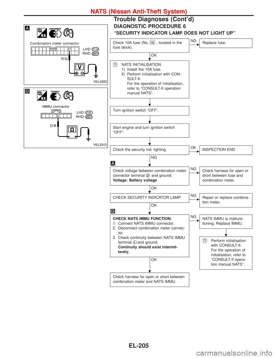
DIAGNOSTIC PROCEDURE 6
ªSECURITY INDICATOR LAMP DOES NOT LIGHT UPº
Check 10A fuse (No.16 , located in the
fuse block).
OK
ENG
Replace fuse.
NATS INITIALISATION
1) Install the 10A fuse.
2) Perform initialisation with CON-
SULT-II.
For the operation of initialisation,
refer to ªCONSULT-II operation
manual NATSº.
Turn ignition switch ªOFFº.
Start engine and turn ignition switch
ªOFFº.
Check the security ind. lighting.
NG
EOK
INSPECTION END
Check voltage between combination meter
connector terminalq
27and ground.
Voltage: Battery voltage
OK
ENG
Check harness for open or
short between fuse and
combination meter.
CHECK SECURITY INDICATOR LAMP.
OK
ENG
Repair or replace combina-
tion meter.
CHECK NATS IMMU FUNCTION.
1. Connect NATS IMMU connector.
2. Disconnect combination meter connec-
tor.
3. Check continuity between NATS IMMU
terminalq
5and ground.
Continuity should exist intermit-
tently.
OK
ENG
NATS IMMU is malfunc-
tioning. Replace IMMU.
Perform initialisation
with CONSULT-II.
For the operation of
initialisation, refer to
ªCONSULT-II opera-
tion manual NATSº.
Check harness for open or short between
combination meter and NATS IMMU.
YEL330D
YEL331D
H
H
H
H
H
H
H
H
H
NATS (Nissan Anti-Theft System)
Trouble Diagnoses (Cont'd)
EL-205