oil capacity NISSAN TERRANO 2002 Service Repair Manual
[x] Cancel search | Manufacturer: NISSAN, Model Year: 2002, Model line: TERRANO, Model: NISSAN TERRANO 2002Pages: 1767, PDF Size: 41.51 MB
Page 1365 of 1767
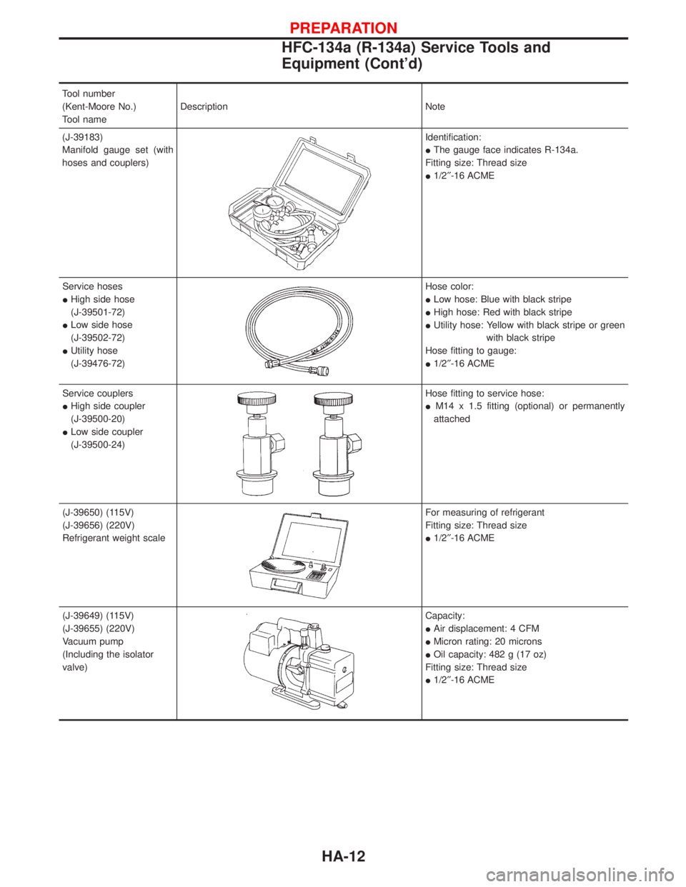
Tool number
(Kent-Moore No.)
Tool nameDescription Note
(J-39183)
Manifold gauge set (with
hoses and couplers)
Identification:
IThe gauge face indicates R-134a.
Fitting size: Thread size
I1/2²-16 ACME
Service hoses
IHigh side hose
(J-39501-72)
ILow side hose
(J-39502-72)
IUtility hose
(J-39476-72)
Hose color:
ILow hose: Blue with black stripe
IHigh hose: Red with black stripe
IUtility hose: Yellow with black stripe or green
with black stripe
Hose fitting to gauge:
I1/2²-16 ACME
Service couplers
IHigh side coupler
(J-39500-20)
ILow side coupler
(J-39500-24)
Hose fitting to service hose:
IM14 x 1.5 fitting (optional) or permanently
attached
(J-39650) (115V)
(J-39656) (220V)
Refrigerant weight scale
For measuring of refrigerant
Fitting size: Thread size
I1/2²-16 ACME
(J-39649) (115V)
(J-39655) (220V)
Vacuum pump
(Including the isolator
valve)
Capacity:
IAir displacement: 4 CFM
IMicron rating: 20 microns
IOil capacity: 482 g (17 oz)
Fitting size: Thread size
I1/2²-16 ACME
PREPARATION
HFC-134a (R-134a) Service Tools and
Equipment (Cont'd)
HA-12
Page 1417 of 1767
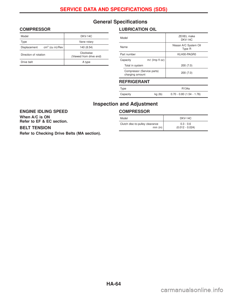
General Specifications
COMPRESSOR
Model DKV-14C
Type Vane rotary
Displacement cm
3(cu in)/Rev 140 (8.54)
Direction of rotationClockwise
(Viewed from drive end)
Drive belt A type
LUBRICATION OIL
ModelZEXEL make
DKV-14C
NameNissan A/C System Oil
Type R
Part number KLH00-PAGR0
Capacity m(Imp fl oz)
Total in system 200 (7.0)
Compressor (Service parts)
charging amount200 (7.0)
REFRIGERANT
Type R134a
Capacity kg (lb) 0.70 - 0.80 (1.54 - 1.76)
Inspection and Adjustment
ENGINE IDLING SPEED
When A/C is ON
Refer to EF & EC section.
BELT TENSION
Refer to Checking Drive Belts (MA section).
COMPRESSOR
Model DKV-14C
Clutch disc-to-pulley clearance
mm (in)0.3 - 0.6
(0.012 - 0.024)
SERVICE DATA AND SPECIFICATIONS (SDS)
HA-64
Page 1422 of 1767
INT/V - Wiring diagram ................................EC-274
Intake air control valve control solenoid
valve .........................................................EC-273
Intake Air Volume .........................................EC-143
Intake door control linkage adjustment ..........HA-63
Intake manifold...............................................EM-12
Interior .............................................................BT-18
Interior lamp ..............................................EL-61, 66
ISO 15031-2 Terminology................................GI-35
K
Knuckle spindle ...............................................FA-20
L
License lamp ...................................................EL-45
Limited slip diff. adjustment............................PD-45
Limited slip diff. assembly ..............................PD-47
Limited slip diff. disassembly ...................PD-43, 44
Limited slip diff. inspection .............................PD-44
Line pressure solenoid valve ..........................AT-84
Line pressure test (A/T) ..........................AT-30, 196
Liquid gasket application .................................EM-3
Location of electrical units ............EL-241, 242, 244
Lock, door ...........................................BT-10, 12, 14
Low and reverse brake .................................AT-161
LSV (Load sensing valve) ..............................BR-10
Lubricants.......................................................MA-17
Lubrication circuit (engine) .........................LC-3, 20
Lubrication oil A/C ....................................HA-22, 64
Lubrication-locks, hinges and hood
latches ..................................................MA-36, 45
Luggage compartment trim .............................BT-18
M
MAFS - Wiring diagram..................................EC-90
MAIN - Wiring diagram...................................EC-80
Main drive gear (M/T) .....................................MT-11
Main gear (Transfer) .................................TF-10, 21
Mainshaft (M/T) ..............................................MT-11
Mainshaft (Transfer)..................................TF-10, 17
Maintenance ...........MA-5, 8, 11, 14, 20, 36, 48, 49
MAJOR OVERHALL ......................................AT-119
Major overhaul (Transfer) .................................TF-9
Malfunction indicator (MI).......................EC-34, 322
Manifold tightening torque (intake &
exhaust) ...............................................MA-20, 28
Manual transmission number ..........................GI-30
Manual transmission oil replacement ......MA-36, 37
Map lamp ........................................................EL-66
Mass air flow sensor (MAFS) ................EC-88, 356
Master cylinder (brake) ..................................BR-16
Meter .........................................................EL-70, 71
METER - Wiring diagram................................EL-72
MIL/DL - Wiring diagram ..............................EC-291MIRROR - Wiring diagram............................EL-131
Mirror, door......................................................BT-48
Model variation ................................................GI-28
Molding - See Exterior ....................................BT-21
M/T major overhaul ........................................MT-10
M/T removal and installation ........................MT-7, 8
Mud guard - See Exterior ...............................BT-21
MULTI - Wiring diagram................................EL-169
Multi-remote control system .........EL-168, 177, 179
Multiport fuel injection precautions ....................GI-5
N
NATS (Nissan anti-theft
system) .....................EL-186, 187, 188, 195, 208
NATS - Wiring diagram .................................EL-189
NATS V2.0 precautions (For Europe) ...............GI-4
Needle lift sensor .........................................EC-427
NVH troubleshooting (EM) ...............................EM-8
O
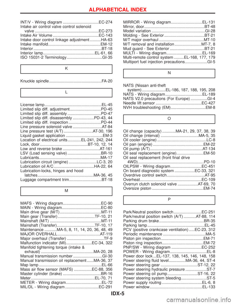
Oil change (capacity) ............MA-21, 29, 37, 38, 39
Oil change (interval) ..................................MA-5, 35
Oil cooler (engine) ............................................LC-8
Oil pan (engine) .............................................EM-22
Oil pump (A/T)...............................................AT-134
Oil seal replacement (engine)........................EM-50
Oil seal replacement (front final drive
4WD)...........................................................PD-10
OILPSW - Wiring diagram............................EC-451
On board diagnostic system ..................EC-33, 321
Overdrive control switch..................................AT-95
Overheat .......................................................EC-109
Overrun clutch solenoid valve ..................AT-69, 70
Oversize piston ..............................................EM-74
P
Park/Neutral position switch .........................EC-251
Park/neutral position switch (A/T) ...........AT-88, 114
Parking drum brake ........................................BR-35
Parking lamp ...................................................EL-45
PCV (positive crankcase ventilation) .....EC-23, 312
Periodic maintenance ......................................MA-5
Piston pin inspection ......................................EM-71
Piston ring inspection.....................................EM-72
PNP/SW - Wiring diagram ...........................EC-252
POWER - Wiring diagram.................................EL-8
Power door lock ...EL-137, 138, 145, 146, 148, 158
Power steering fluid level...............MA-36, 44, ST-4
Power steering gear .................................ST-12, 22
Power steering hydraulic pressure ...................ST-7
Power steering oil pump ...........................ST-16, 22
Power steering system bleeding.......................ST-5
Power supply routing ....................................EL-6, 8
Power window ...............................................EL-133
ALPHABETICAL INDEX
IDX-5
Page 1476 of 1767
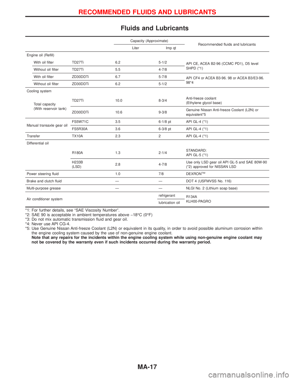
Fluids and Lubricants
Capacity (Approximate)
Recommended fluids and lubricants
Liter Imp qt
Engine oil (Refill)
With oil filter TD27Ti 6.2 5-1/2
API CE, ACEA B2-96 (CCMC PD1), D5 level
SHPD (*1)
Without oil filter TD27Ti 5.5 4-7/8
With oil filter ZD30DDTi 6.7 5-7/8
API CF4 or ACEA B3-96. 98 or ACEA B3/E3-96.
98*4
Without oil filter ZD30DDTi 6.2 5-1/2
Cooling system
Total capacity
(With reservoir tank)TD27Ti 10.0 8-3/4Anti-freeze coolant
(Ethylene glycol base)
ZD30DDTi 10.6 9-3/8Genuine Nissan Anti-freeze Coolant (L2N) or
equivalent*5
Manual transaxle gear oilFS5W71C 3.5 6-1/8 pt API GL-4 (*1)
FS5R30A 3.6 6-3/8 pt API GL-4 (*1)
Transfer TX10A 2.3 2 API GL-4 (*1)
Differential oil
R180A 1.3 2-1/4STANDARD:
API GL-5 (*1)
H233B
(LSD)2.8 4-7/8Use only LSD gear oil API GL-5 and SAE 80W-90
(*2) approved for NISSAN LSD
Power steering fluid 1.0 7/8 DEXRON
TM
Brake and clutch fluid Ð Ð DOT 4 (USFMVSS No. 116)
Multi-purpose grease Ð Ð NLGI No. 2 (Lithium soap base)
Air conditioner systemrefrigerant
R134A
KLH00-PAGRO
lubrication oil
*1: For further details, see ªSAE Viscosity Numberº.
*2: SAE 90 is acceptable in ambient temperatures above þ18ÉC (0ÉF)
*3: Do not mix automatic transmission fluid and gear oil.
*4: Never use API CG-4.
*5: Use Genuine Nissan Anti-freeze Coolant (L2N) or equivalent in its quality, in order to avoid possible aluminum corrosion within
the engine cooling system caused by the use of non-genuine engine coolant.
Note that any repairs for the incidents within the engine cooling system while using non-genuine engine coolant may
not be covered by the warranty even if such incidents occurred during the warranty period.
RECOMMENDED FLUIDS AND LUBRICANTS
MA-17
Page 1480 of 1767
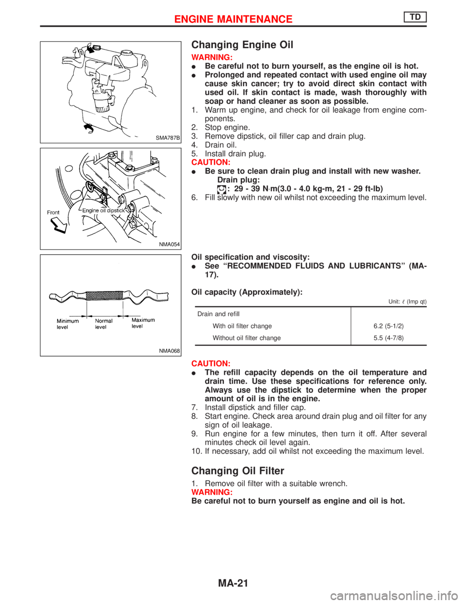
Changing Engine Oil
WARNING:
IBe careful not to burn yourself, as the engine oil is hot.
IProlonged and repeated contact with used engine oil may
cause skin cancer; try to avoid direct skin contact with
used oil. If skin contact is made, wash thoroughly with
soap or hand cleaner as soon as possible.
1. Warm up engine, and check for oil leakage from engine com-
ponents.
2. Stop engine.
3. Remove dipstick, oil filler cap and drain plug.
4. Drain oil.
5. Install drain plug.
CAUTION:
IBe sure to clean drain plug and install with new washer.
Drain plug:
: 29-39N×m(3.0 - 4.0 kg-m, 21 - 29 ft-lb)
6. Fill slowly with new oil whilst not exceeding the maximum level.
Oil specification and viscosity:
ISee ªRECOMMENDED FLUIDS AND LUBRICANTSº (MA-
17).
Oil capacity (Approximately):
Unit:(Imp qt)
Drain and refill
With oil filter change 6.2 (5-1/2)
Without oil filter change 5.5 (4-7/8)
CAUTION:
IThe refill capacity depends on the oil temperature and
drain time. Use these specifications for reference only.
Always use the dipstick to determine when the proper
amount of oil is in the engine.
7. Install dipstick and filler cap.
8. Start engine. Check area around drain plug and oil filter for any
sign of oil leakage.
9. Run engine for a few minutes, then turn it off. After several
minutes check oil level again.
10. If necessary, add oil whilst not exceeding the maximum level.
Changing Oil Filter
1. Remove oil filter with a suitable wrench.
WARNING:
Be careful not to burn yourself as engine and oil is hot.
SMA787B
NMA054
NMA068
ENGINE MAINTENANCETD
MA-21
Page 1481 of 1767
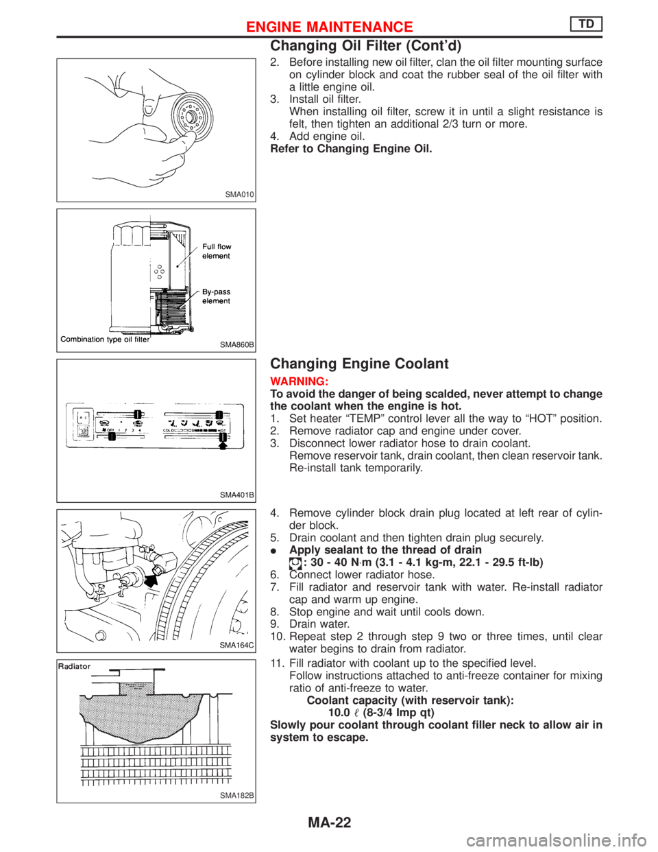
2. Before installing new oil filter, clan the oil filter mounting surface
on cylinder block and coat the rubber seal of the oil filter with
a little engine oil.
3. Install oil filter.
When installing oil filter, screw it in until a slight resistance is
felt, then tighten an additional 2/3 turn or more.
4. Add engine oil.
Refer to Changing Engine Oil.
Changing Engine Coolant
WARNING:
To avoid the danger of being scalded, never attempt to change
the coolant when the engine is hot.
1. Set heater ªTEMPº control lever all the way to ªHOTº position.
2. Remove radiator cap and engine under cover.
3. Disconnect lower radiator hose to drain coolant.
Remove reservoir tank, drain coolant, then clean reservoir tank.
Re-install tank temporarily.
4. Remove cylinder block drain plug located at left rear of cylin-
der block.
5. Drain coolant and then tighten drain plug securely.
IApply sealant to the thread of drain
:30-40N×m (3.1 - 4.1 kg-m, 22.1 - 29.5 ft-lb)
6. Connect lower radiator hose.
7. Fill radiator and reservoir tank with water. Re-install radiator
cap and warm up engine.
8. Stop engine and wait until cools down.
9. Drain water.
10. Repeat step 2 through step 9 two or three times, until clear
water begins to drain from radiator.
11. Fill radiator with coolant up to the specified level.
Follow instructions attached to anti-freeze container for mixing
ratio of anti-freeze to water.
Coolant capacity (with reservoir tank):
10.0(8-3/4 Imp qt)
Slowly pour coolant through coolant filler neck to allow air in
system to escape.
SMA010
SMA860B
SMA401B
SMA164C
SMA182B
ENGINE MAINTENANCETD
Changing Oil Filter (Cont'd)
MA-22
Page 1489 of 1767
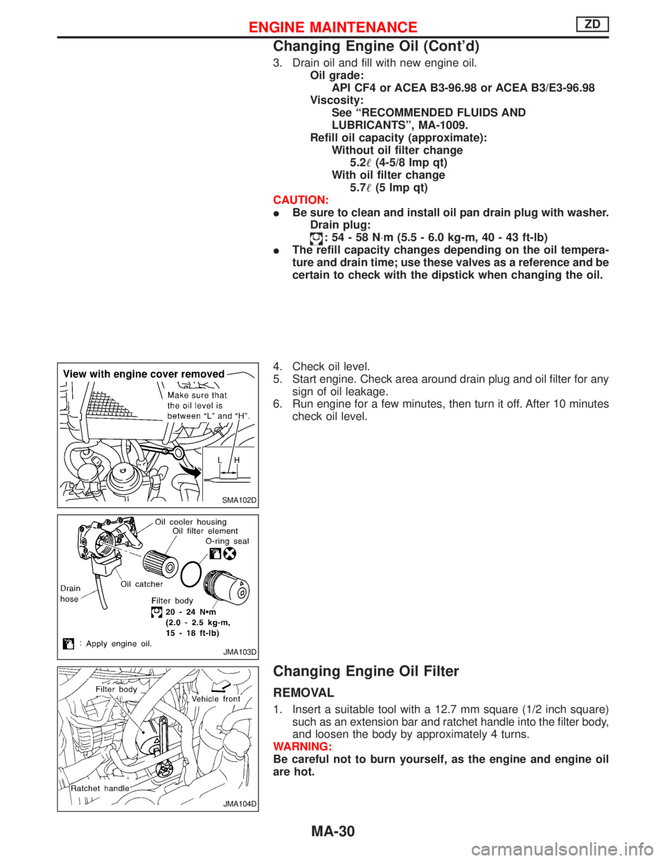
3. Drain oil and fill with new engine oil.
Oil grade:
API CF4 or ACEA B3-96.98 or ACEA B3/E3-96.98
Viscosity:
See ªRECOMMENDED FLUIDS AND
LUBRICANTSº, MA-1009.
Refill oil capacity (approximate):
Without oil filter change
5.2(4-5/8 Imp qt)
With oil filter change
5.7(5 Imp qt)
CAUTION:
IBe sure to clean and install oil pan drain plug with washer.
Drain plug:
:54-58N×m (5.5 - 6.0 kg-m, 40 - 43 ft-lb)
IThe refill capacity changes depending on the oil tempera-
ture and drain time; use these valves as a reference and be
certain to check with the dipstick when changing the oil.
4. Check oil level.
5. Start engine. Check area around drain plug and oil filter for any
sign of oil leakage.
6. Run engine for a few minutes, then turn it off. After 10 minutes
check oil level.
Changing Engine Oil Filter
REMOVAL
1. Insert a suitable tool with a 12.7 mm square (1/2 inch square)
such as an extension bar and ratchet handle into the filter body,
and loosen the body by approximately 4 turns.
WARNING:
Be careful not to burn yourself, as the engine and engine oil
are hot.
SMA102D
JMA103D
JMA104D
ENGINE MAINTENANCEZD
Changing Engine Oil (Cont'd)
MA-30
Page 1496 of 1767
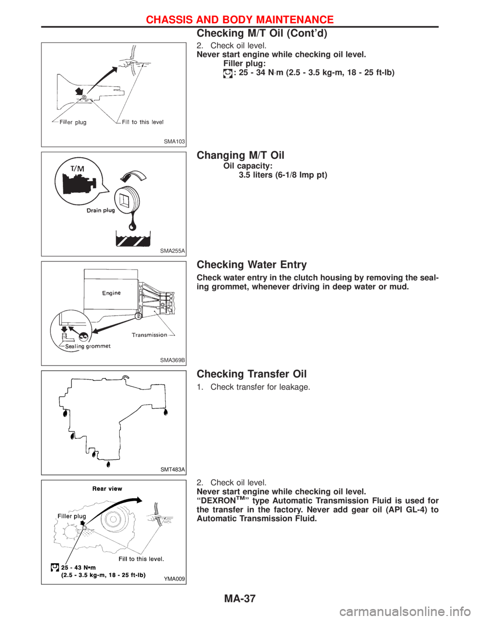
2. Check oil level.
Never start engine while checking oil level.
Filler plug:
:25-34N×m (2.5 - 3.5 kg-m, 18 - 25 ft-lb)
Changing M/T Oil
Oil capacity:
3.5 liters (6-1/8 Imp pt)
Checking Water Entry
Check water entry in the clutch housing by removing the seal-
ing grommet, whenever driving in deep water or mud.
Checking Transfer Oil
1. Check transfer for leakage.
2. Check oil level.
Never start engine while checking oil level.
ªDEXRON
TMº type Automatic Transmission Fluid is used for
the transfer in the factory. Never add gear oil (API GL-4) to
Automatic Transmission Fluid.
SMA103
SMA255A
SMA369B
SMT483A
YMA009
CHASSIS AND BODY MAINTENANCE
Checking M/T Oil (Cont'd)
MA-37
Page 1497 of 1767
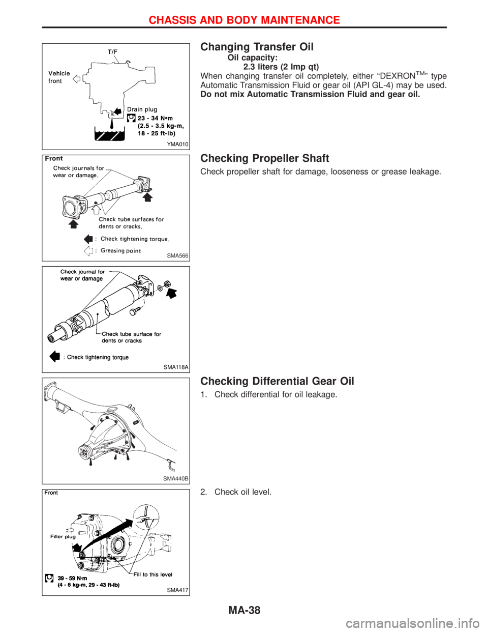
Changing Transfer Oil
Oil capacity:
2.3 liters (2 Imp qt)
When changing transfer oil completely, either ªDEXRON
TMº type
Automatic Transmission Fluid or gear oil (API GL-4) may be used.
Do not mix Automatic Transmission Fluid and gear oil.
Checking Propeller Shaft
Check propeller shaft for damage, looseness or grease leakage.
Checking Differential Gear Oil
1. Check differential for oil leakage.
2. Check oil level.
YMA010
SMA566
SMA118A
SMA440B
SMA417
CHASSIS AND BODY MAINTENANCE
MA-38
Page 1498 of 1767
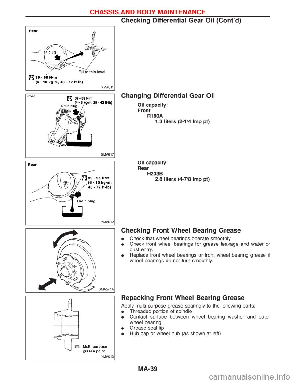
Changing Differential Gear Oil
Oil capacity:
Front
R180A
1.3 liters (2-1/4 Imp pt)
Oil capacity:
Rear
H233B
2.8 liters (4-7/8 Imp pt)
Checking Front Wheel Bearing Grease
ICheck that wheel bearings operate smoothly.
ICheck front wheel bearings for grease leakage and water or
dust entry.
IReplace front wheel bearings or front wheel bearing grease if
wheel bearings do not turn smoothly.
Repacking Front Wheel Bearing Grease
Apply multi-purpose grease sparingly to the following parts:
IThreaded portion of spindle
IContact surface between wheel bearing washer and outer
wheel bearing
IGrease seal lip
IHub cap or wheel hub (as shown at left)
YMA011
SMA617
YMA012
SMA571A
YMA013
CHASSIS AND BODY MAINTENANCE
Checking Differential Gear Oil (Cont'd)
MA-39