resistor NISSAN TERRANO 2002 Service Repair Manual
[x] Cancel search | Manufacturer: NISSAN, Model Year: 2002, Model line: TERRANO, Model: NISSAN TERRANO 2002Pages: 1767, PDF Size: 41.51 MB
Page 33 of 1767
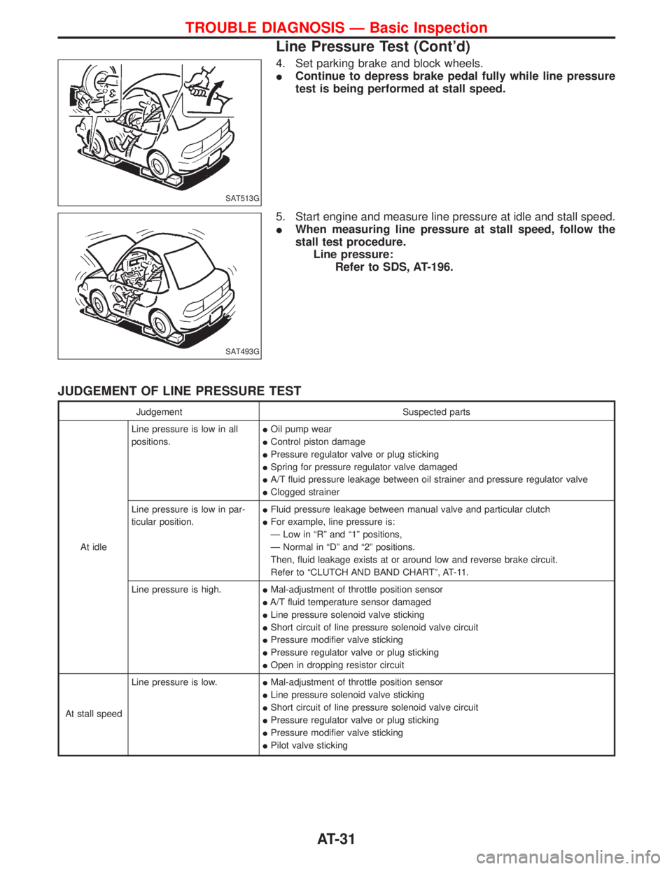
4. Set parking brake and block wheels.
IContinue to depress brake pedal fully while line pressure
test is being performed at stall speed.
5. Start engine and measure line pressure at idle and stall speed.
IWhen measuring line pressure at stall speed, follow the
stall test procedure.
Line pressure:
Refer to SDS, AT-196.
JUDGEMENT OF LINE PRESSURE TEST
Judgement Suspected parts
At idleLine pressure is low in all
positions.IOil pump wear
IControl piston damage
IPressure regulator valve or plug sticking
ISpring for pressure regulator valve damaged
IA/T fluid pressure leakage between oil strainer and pressure regulator valve
IClogged strainer
Line pressure is low in par-
ticular position.IFluid pressure leakage between manual valve and particular clutch
IFor example, line pressure is:
Ð Low in ªRº and ª1º positions,
Ð Normal in ªDº and ª2º positions.
Then, fluid leakage exists at or around low and reverse brake circuit.
Refer to ªCLUTCH AND BAND CHARTº, AT-11.
Line pressure is high.IMal-adjustment of throttle position sensor
IA/T fluid temperature sensor damaged
ILine pressure solenoid valve sticking
IShort circuit of line pressure solenoid valve circuit
IPressure modifier valve sticking
IPressure regulator valve or plug sticking
IOpen in dropping resistor circuit
At stall speedLine pressure is low.IMal-adjustment of throttle position sensor
ILine pressure solenoid valve sticking
IShort circuit of line pressure solenoid valve circuit
IPressure regulator valve or plug sticking
IPressure modifier valve sticking
IPilot valve sticking
SAT513G
SAT493G
TROUBLE DIAGNOSIS Ð Basic Inspection
Line Pressure Test (Cont'd)
AT-31
Page 48 of 1767
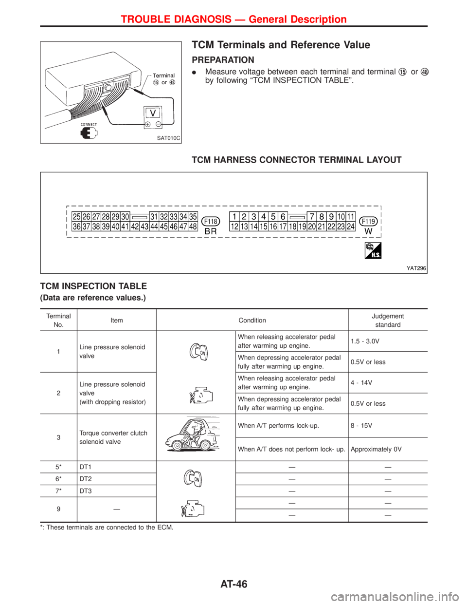
TCM Terminals and Reference Value
PREPARATION
IMeasure voltage between each terminal and terminalq15orq48
by following ªTCM INSPECTION TABLEº.
TCM HARNESS CONNECTOR TERMINAL LAYOUT
TCM INSPECTION TABLE
(Data are reference values.)
Terminal
No.Item ConditionJudgement
standard
1Line pressure solenoid
valve
When releasing accelerator pedal
after warming up engine.1.5 - 3.0V
When depressing accelerator pedal
fully after warming up engine.0.5V or less
2Line pressure solenoid
valve
(with dropping resistor)When releasing accelerator pedal
after warming up engine.4 - 14V
When depressing accelerator pedal
fully after warming up engine.0.5V or less
3Torque converter clutch
solenoid valve
When A/T performs lock-up. 8 - 15V
When A/T does not perform lock- up. Approximately 0V
5* DT1
ÐÐ
6* DT2 Ð Ð
7* DT3 Ð Ð
9ÐÐÐ
ÐÐ
*: These terminals are connected to the ECM.
SAT010C
YAT296
TROUBLE DIAGNOSIS Ð General Description
AT-46
Page 83 of 1767
DIAGNOSTIC PROCEDURE
Perform diagnostic test mode II (self-
diagnostic results) for engine control.
Check ignition signal circuit condition.
OK
ENG
Check ignition signal circuit
for engine control. Refer to
EC section [TROUBLE
DIAGNOSIS FOR ªIGN
SIGNAL-PRIMARYº (DTC
21)].
CHECK INPUT SIGNAL.
1. Start engine.
2. Select ªECU INPUT SIGNALSº in
Data Monitor.
3. Read out the value of ªENGINE
SPEEDº.
Check engine speed changes
according to throttle position.
-----------------------------------------------------------------------------------------------------------------------OR -----------------------------------------------------------------------------------------------------------------------
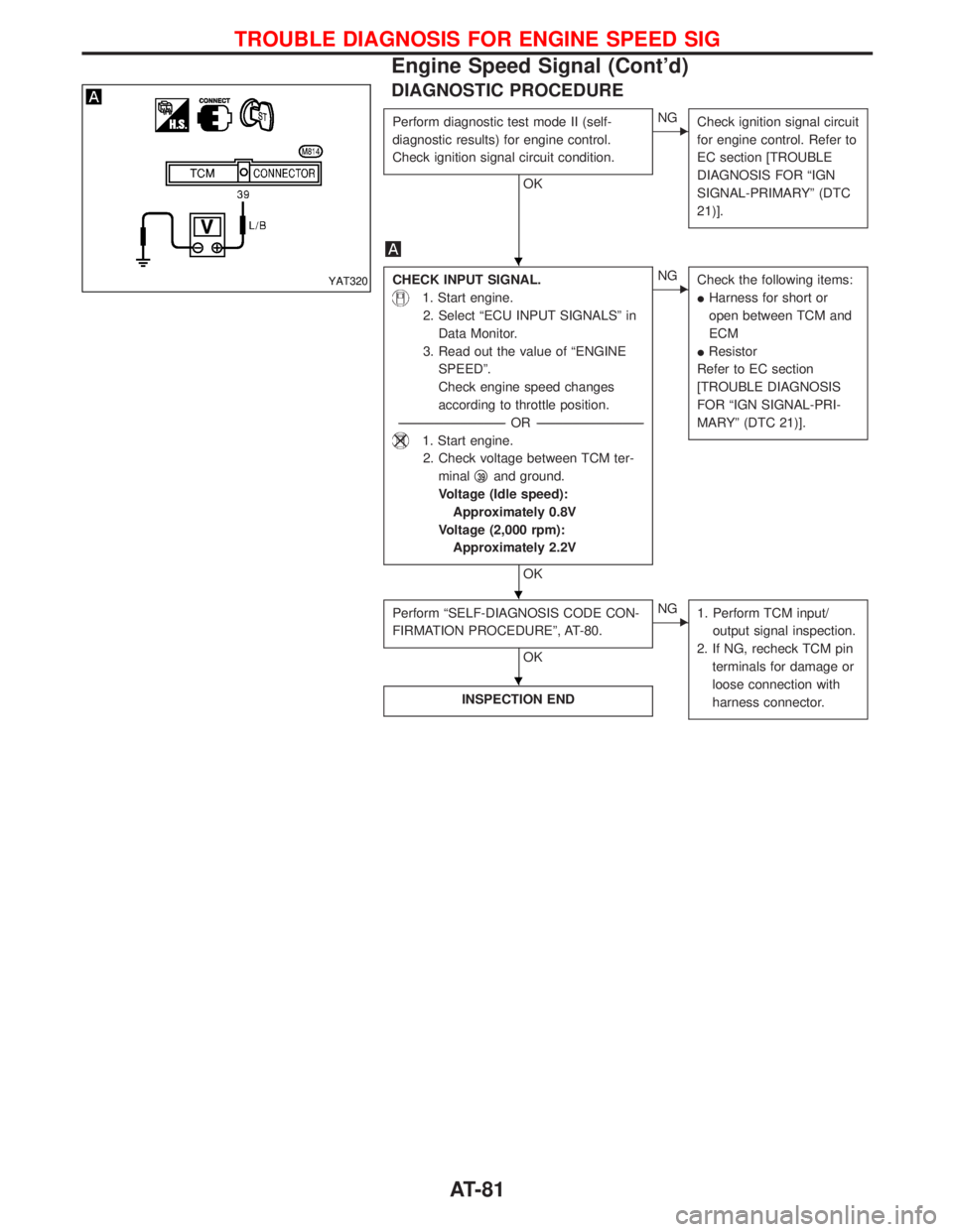
1. Start engine.
2. Check voltage between TCM ter-
minalq
39and ground.
Voltage (Idle speed):
Approximately 0.8V
Voltage (2,000 rpm):
Approximately 2.2V
OK
ENG
Check the following items:
IHarness for short or
open between TCM and
ECM
IResistor
Refer to EC section
[TROUBLE DIAGNOSIS
FOR ªIGN SIGNAL-PRI-
MARYº (DTC 21)].
Perform ªSELF-DIAGNOSIS CODE CON-
FIRMATION PROCEDUREº, AT-80.
OK
ENG
1. Perform TCM input/
output signal inspection.
2. If NG, recheck TCM pin
terminals for damage or
loose connection with
harness connector.
INSPECTION END
YAT320
H
H
H
TROUBLE DIAGNOSIS FOR ENGINE SPEED SIG
Engine Speed Signal (Cont'd)
AT-81
Page 87 of 1767
DIAGNOSTIC PROCEDURE
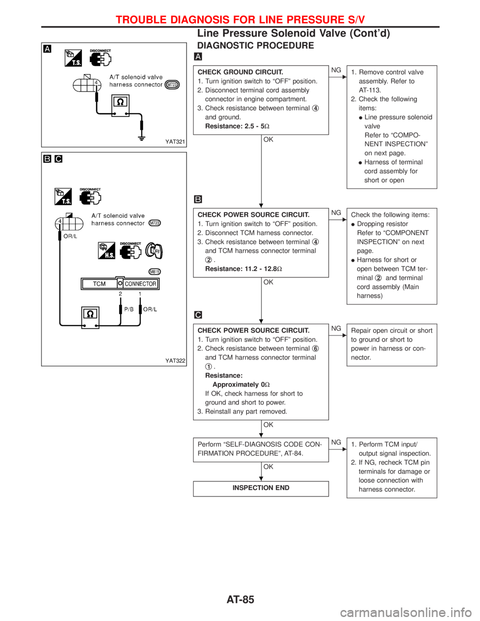
CHECK GROUND CIRCUIT.
1. Turn ignition switch to ªOFFº position.
2. Disconnect terminal cord assembly
connector in engine compartment.
3. Check resistance between terminalq
4
and ground.
Resistance: 2.5 - 5W
OK
ENG
1. Remove control valve
assembly. Refer to
AT-113.
2. Check the following
items:
ILine pressure solenoid
valve
Refer to ªCOMPO-
NENT INSPECTIONº
on next page.
IHarness of terminal
cord assembly for
short or open
CHECK POWER SOURCE CIRCUIT.
1. Turn ignition switch to ªOFFº position.
2. Disconnect TCM harness connector.
3. Check resistance between terminalq
4
and TCM harness connector terminal
q
2.
Resistance: 11.2 - 12.8W
OK
ENG
Check the following items:
IDropping resistor
Refer to ªCOMPONENT
INSPECTIONº on next
page.
IHarness for short or
open between TCM ter-
minalq
2and terminal
cord assembly (Main
harness)
CHECK POWER SOURCE CIRCUIT.
1. Turn ignition switch to ªOFFº position.
2. Check resistance between terminalq
6
and TCM harness connector terminal
q
1.
Resistance:
Approximately 0W
If OK, check harness for short to
ground and short to power.
3. Reinstall any part removed.
OK
ENG
Repair open circuit or short
to ground or short to
power in harness or con-
nector.
Perform ªSELF-DIAGNOSIS CODE CON-
FIRMATION PROCEDUREº, AT-84.
OK
ENG
1. Perform TCM input/
output signal inspection.
2. If NG, recheck TCM pin
terminals for damage or
loose connection with
harness connector.
INSPECTION END
YAT321
YAT322
H
H
H
H
TROUBLE DIAGNOSIS FOR LINE PRESSURE S/V
Line Pressure Solenoid Valve (Cont'd)
AT-85
Page 88 of 1767
COMPONENT INSPECTION
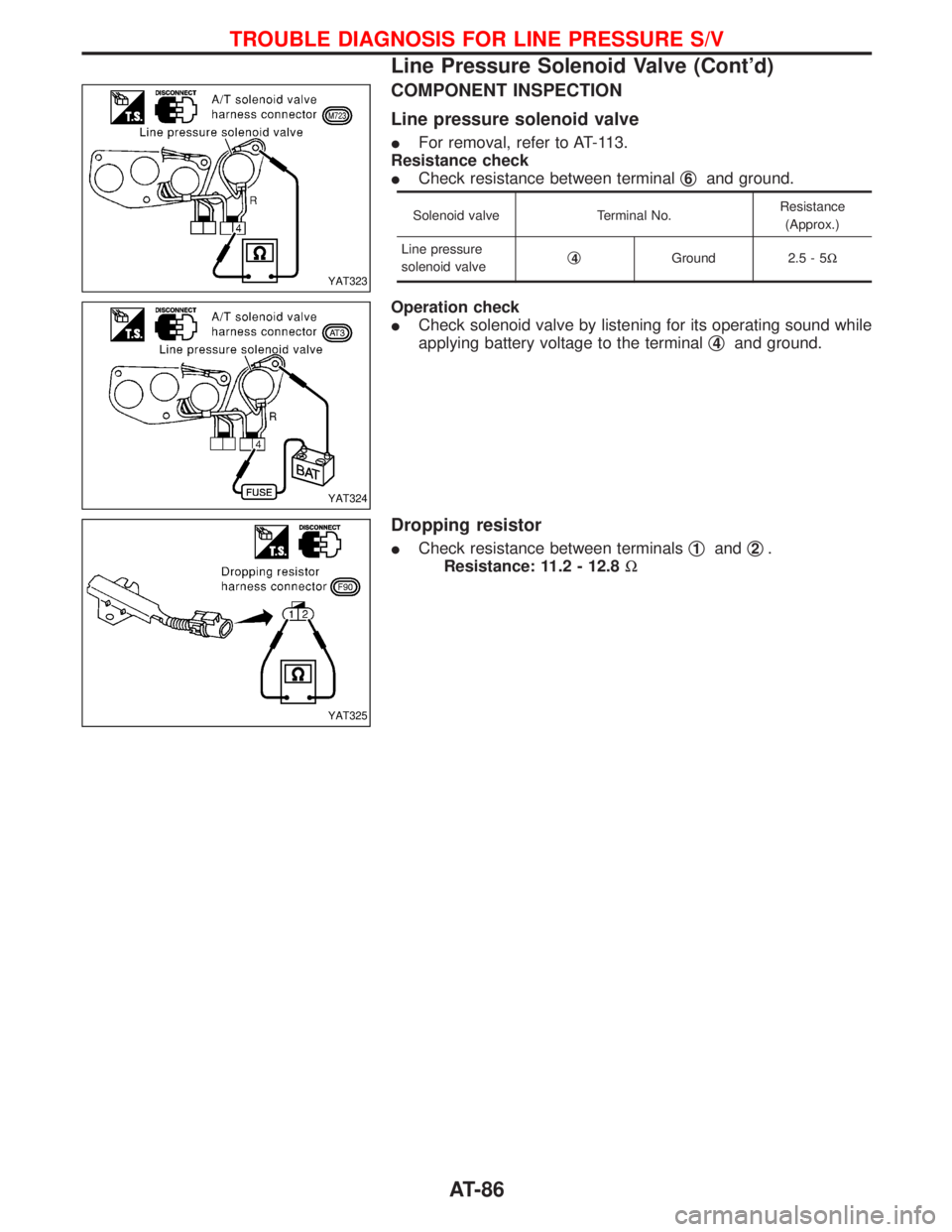
Line pressure solenoid valve
IFor removal, refer to AT-113.
Resistance check
ICheck resistance between terminalq
6and ground.
Solenoid valve Terminal No.Resistance
(Approx.)
Line pressure
solenoid valveq
4Ground 2.5 - 5W
Operation check
ICheck solenoid valve by listening for its operating sound while
applying battery voltage to the terminalq
4and ground.
Dropping resistor
ICheck resistance between terminalsq1andq2.
Resistance: 11.2 - 12.8W
YAT323
YAT324
YAT325
TROUBLE DIAGNOSIS FOR LINE PRESSURE S/V
Line Pressure Solenoid Valve (Cont'd)
AT-86
Page 473 of 1767
Overall Function Check
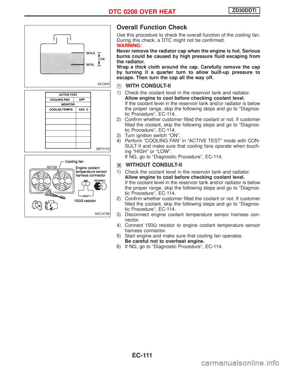
Use this procedure to check the overall function of the cooling fan.
During this check, a DTC might not be confirmed.
WARNING:
Never remove the radiator cap when the engine is hot. Serious
burns could be caused by high pressure fluid escaping from
the radiator.
Wrap a thick cloth around the cap. Carefully remove the cap
by turning it a quarter turn to allow built-up pressure to
escape. Then turn the cap all the way off.
WITH CONSULT-II
1) Check the coolant level in the reservoir tank and radiator.
Allow engine to cool before checking coolant level.
If the coolant level in the reservoir tank and/or radiator is below
the proper range, skip the following steps and go to ªDiagnos-
tic Procedureº, EC-114.
2) Confirm whether customer filled the coolant or not. If customer
filled the coolant, skip the following steps and go to ªDiagnos-
tic Procedureº, EC-114.
3) Turn ignition switch ªONº.
4) Perform ªCOOLING FANº in ªACTIVE TESTº mode with CON-
SULT-II and make sure that cooling fans operate when touch-
ing ªHIGHº or ªLOWº.
If NG, go to ªDiagnostic Procedureº, EC-114.
WITHOUT CONSULT-II
1) Check the coolant level in the reservoir tank and radiator.
Allow engine to cool before checking coolant level.
If the coolant level in the reservoir tank and/or radiator is below
the proper range, skip the following steps and go to ªDiagnos-
tic Procedureº, EC-114.
2) Confirm whether customer filled the coolant or not. If customer
filled the coolant, skip the following steps and go to ªDiagnos-
tic Procedureº, EC-114.
3) Disconnect engine coolant temperature sensor harness con-
nector.
4) Connect 150Wresistor to engine coolant temperature sensor
harness connector.
5) Start engine and make sure that cooling fan operates.
Be careful not to overheat engine.
6) If NG, go to ªDiagnostic Procedureº, EC-114.
AEC640
SEF111X
MEC475B
DTC 0208 OVER HEATZD30DDTi
EC-111
Page 476 of 1767
Diagnostic Procedure
1 INSPECTION START
Do you have CONSULT-II?
YesorNo
Ye sEGO TO 2.
NoEGO TO 3.
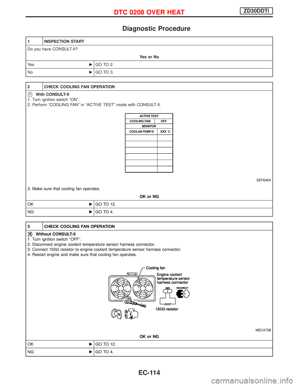
2 CHECK COOLING FAN OPERATION
With CONSULT-II
1. Turn ignition switch ªONº.
2. Perform ªCOOLING FANº in ªACTIVE TESTº mode with CONSULT-II.
SEF646X
3. Make sure that cooling fan operates.
OK or NG
OKEGO TO 12.
NGEGO TO 4.
3 CHECK COOLING FAN OPERATION
Without CONSULT-II
1. Turn ignition switch ªOFFº.
2. Disconnect engine coolant temperature sensor harness connector.
3. Connect 150Wresistor to engine coolant temperature sensor harness connector.
4. Restart engine and make sure that cooling fan operates.
MEC475B
OK or NG
OKEGO TO 12.
NGEGO TO 4.
DTC 0208 OVER HEATZD30DDTi
EC-114
Page 781 of 1767
Overall Function Check
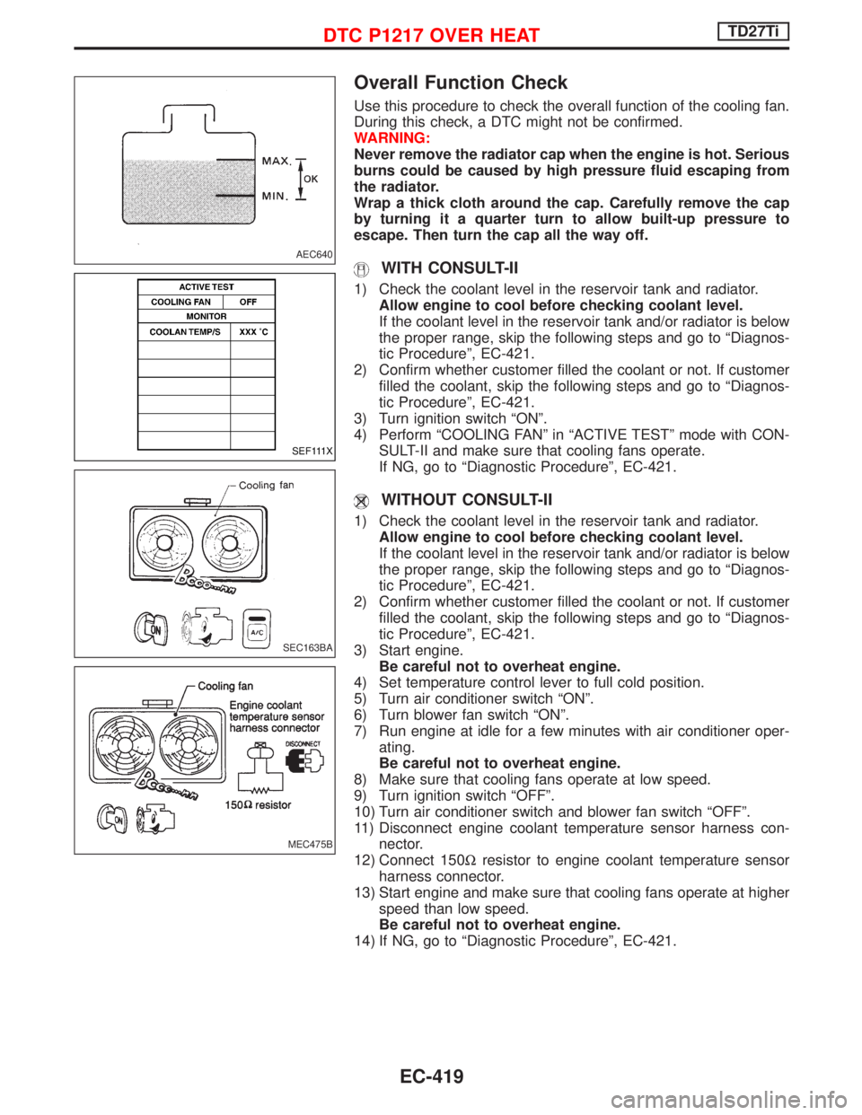
Use this procedure to check the overall function of the cooling fan.
During this check, a DTC might not be confirmed.
WARNING:
Never remove the radiator cap when the engine is hot. Serious
burns could be caused by high pressure fluid escaping from
the radiator.
Wrap a thick cloth around the cap. Carefully remove the cap
by turning it a quarter turn to allow built-up pressure to
escape. Then turn the cap all the way off.
WITH CONSULT-II
1) Check the coolant level in the reservoir tank and radiator.
Allow engine to cool before checking coolant level.
If the coolant level in the reservoir tank and/or radiator is below
the proper range, skip the following steps and go to ªDiagnos-
tic Procedureº, EC-421.
2) Confirm whether customer filled the coolant or not. If customer
filled the coolant, skip the following steps and go to ªDiagnos-
tic Procedureº, EC-421.
3) Turn ignition switch ªONº.
4) Perform ªCOOLING FANº in ªACTIVE TESTº mode with CON-
SULT-II and make sure that cooling fans operate.
If NG, go to ªDiagnostic Procedureº, EC-421.
WITHOUT CONSULT-II
1) Check the coolant level in the reservoir tank and radiator.
Allow engine to cool before checking coolant level.
If the coolant level in the reservoir tank and/or radiator is below
the proper range, skip the following steps and go to ªDiagnos-
tic Procedureº, EC-421.
2) Confirm whether customer filled the coolant or not. If customer
filled the coolant, skip the following steps and go to ªDiagnos-
tic Procedureº, EC-421.
3) Start engine.
Be careful not to overheat engine.
4) Set temperature control lever to full cold position.
5) Turn air conditioner switch ªONº.
6) Turn blower fan switch ªONº.
7) Run engine at idle for a few minutes with air conditioner oper-
ating.
Be careful not to overheat engine.
8) Make sure that cooling fans operate at low speed.
9) Turn ignition switch ªOFFº.
10) Turn air conditioner switch and blower fan switch ªOFFº.
11) Disconnect engine coolant temperature sensor harness con-
nector.
12) Connect 150Wresistor to engine coolant temperature sensor
harness connector.
13) Start engine and make sure that cooling fans operate at higher
speed than low speed.
Be careful not to overheat engine.
14) If NG, go to ªDiagnostic Procedureº, EC-421.
AEC640
SEF111X
SEC163BA
MEC475B
DTC P1217 OVER HEATTD27Ti
EC-419
Page 994 of 1767
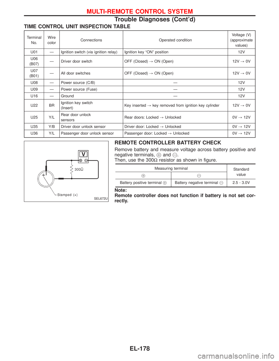
TIME CONTROL UNIT INSPECTION TABLE
Terminal
No.Wire
colorConnections Operated conditionVoltage (V)
(approximate
values)
U01 Ð Ignition switch (via ignition relay) Ignition key ªONº position 12V
U06
(B07)Ð Driver door switch OFF (Closed),ON (Open) 12V,0V
U07
(B01)Ð All door switches OFF (Closed),ON (Open) 12V,0V
U08 Ð Power source (C/B) Ð 12V
U09 Ð Power source (Fuse) Ð 12V
U16 Ð Ground Ð 12V
U22 BRIgnition key switch
(Insert)Key inserted,key removed from ignition key cylinder 12V,0V
U25 Y/LRear door unlock
sensorsRear doors: Locked,Unlocked 0V,12V
U35 Y/B Driver door unlock sensor Driver door: Locked,Unlocked 0V,12V
U36 Y/L Passenger door unlock sensor Passenger door: Locked,Unlocked 0V,12V
REMOTE CONTROLLER BATTERY CHECK
Remove battery and measure voltage across battery positive and
negative terminals,!and@.
Then, use the 300Wresistor as shown in figure.
Measuring terminal
Standard
value
!@
Battery positive terminal!Battery negative [email protected] - 3.0V
Note:
Remote controller does not function if battery is not set cor-
rectly.
SEL672U
MULTI-REMOTE CONTROL SYSTEM
Trouble Diagnoses (Cont'd)
EL-178
Page 1389 of 1767
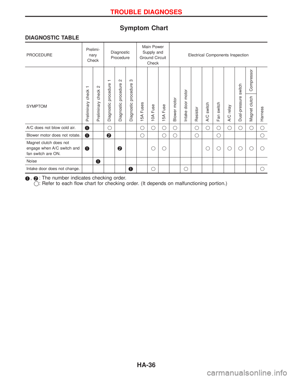
Symptom Chart
DIAGNOSTIC TABLE
PROCEDUREPrelimi-
nary
CheckDiagnostic
ProcedureMain Power
Supply and
Ground Circuit
CheckElectrical Components Inspection
SYMPTOM
Preliminary check 1
Preliminary check 2
Diagnostic procedure 1
Diagnostic procedure 2
Diagnostic procedure 3
15A Fuses
10A Fuse
15A Fuse
Blower motor
Intake door motor
Resistor
A/C switch
Fan switch
A/C relay
Dual-pressure switch
Compressor
Harness Magnet clutch
A/C does not blow cold air.q qqqq qqqqqqq
Blower motor does not rotate.
qqqqq q
Magnet clutch does not
engage when A/C switch and
fan switch are ON.
qq qqqqqq
Noise
Intake door does not change.qq q
,: The number indicates checking order.
q: Refer to each flow chart for checking order. (It depends on malfunctioning portion.)
TROUBLE DIAGNOSES
HA-36