bulb NISSAN TERRANO 2002 Service Repair Manual
[x] Cancel search | Manufacturer: NISSAN, Model Year: 2002, Model line: TERRANO, Model: NISSAN TERRANO 2002Pages: 1767, PDF Size: 41.51 MB
Page 267 of 1767
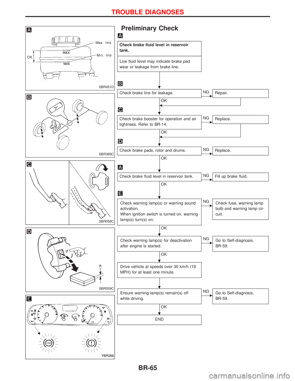
Preliminary Check
Check brake fluid level in reservoir
tank.
----------------------------------------------------------------------------------------------------------------------------------------------------------------------------------------------------------------------------------------------------------------------------------------------------------------
Low fluid level may indicate brake pad
wear or leakage from brake line.
Check brake line for leakage.
OKENG
Repair.
F
Check brake booster for operation and air
tightness. Refer to BR-14.
OK
ENG
Replace.
F
Check brake pads, rotor and drums.
OKENG
Replace.
Check brake fluid level in reservoir tank.
OKENG
Fill up brake fluid.
Check warning lamp(s) or warning sound
activation.
When ignition switch is turned on, warning
lamp(s) turn(s) on.
OK
ENG
Check fuse, warning lamp
bulb and warning lamp cir-
cuit.
Check warning lamp(s) for deactivation
after engine is started.
OK
ENG
Go to Self-diagnosis,
BR-59.
Drive vehicle at speeds over 30 km/h (19
MPH) for at least one minute.
Ensure warning lamp(s) remain(s) off
while driving.
OK
ENG
Go to Self-diagnosis,
BR-59.
END
SBR451D
SBR389C
SBR058C
SBR059C
YBR266
H
H
H
H
H
H
H
H
H
TROUBLE DIAGNOSES
BR-65
Page 269 of 1767
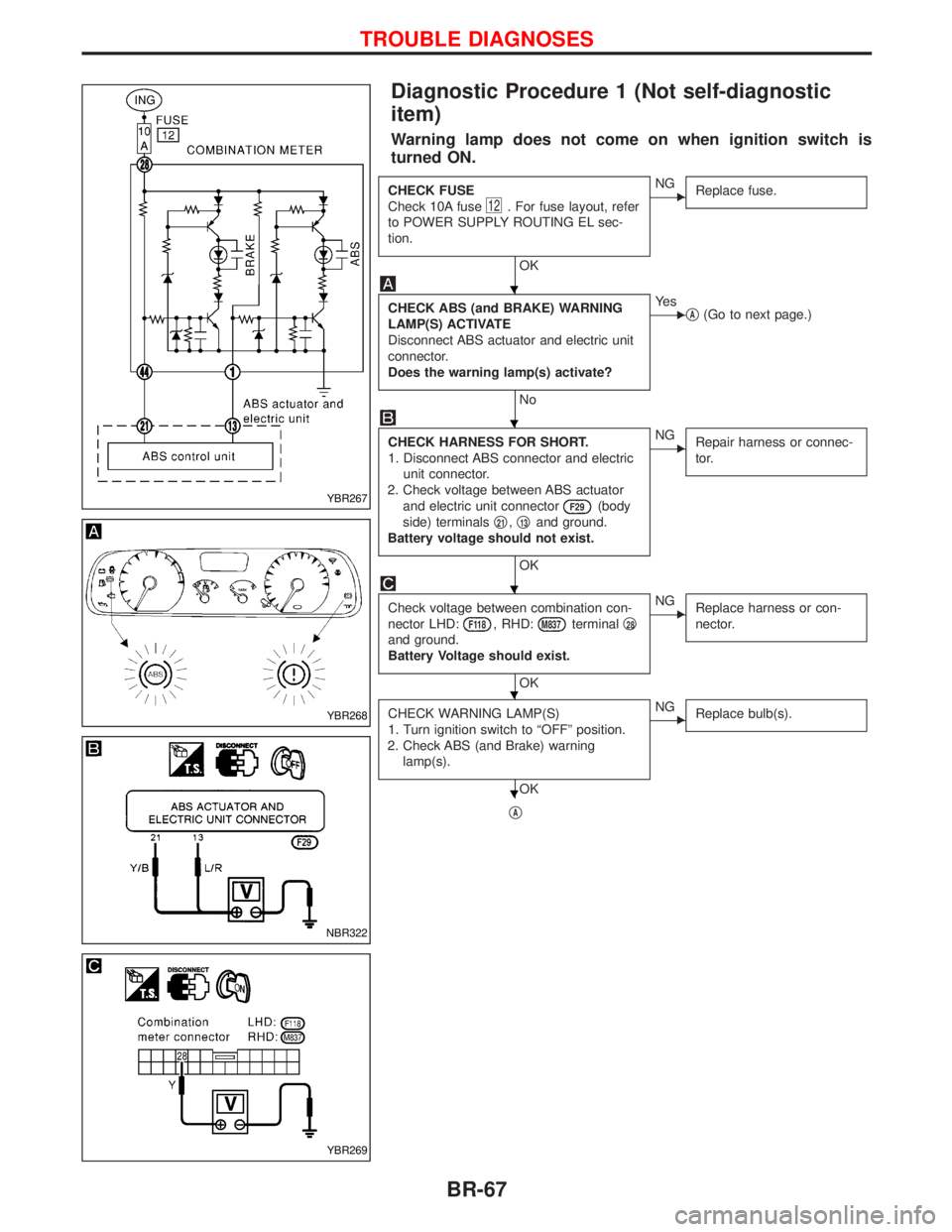
Diagnostic Procedure 1 (Not self-diagnostic
item)
Warning lamp does not come on when ignition switch is
turned ON.
CHECK FUSE
Check 10A fuse
12. For fuse layout, refer
to POWER SUPPLY ROUTING EL sec-
tion.
OK
ENG
Replace fuse.
CHECK ABS (and BRAKE) WARNING
LAMP(S) ACTIVATE
Disconnect ABS actuator and electric unit
connector.
Does the warning lamp(s) activate?
No
EYe s
qA(Go to next page.)
CHECK HARNESS FOR SHORT.
1. Disconnect ABS connector and electric
unit connector.
2. Check voltage between ABS actuator
and electric unit connector
F29(body
side) terminalsq
21,q13and ground.
Battery voltage should not exist.
OK
ENG
Repair harness or connec-
tor.
Check voltage between combination con-
nector LHD:
F118, RHD:M837terminalq28
and ground.
Battery Voltage should exist.
OK
ENG
Replace harness or con-
nector.
CHECK WARNING LAMP(S)
1. Turn ignition switch to ªOFFº position.
2. Check ABS (and Brake) warning
lamp(s).
OK
ENG
Replace bulb(s).
qA
YBR267
YBR268
NBR322
YBR269
H
H
H
H
H
TROUBLE DIAGNOSES
BR-67
Page 396 of 1767
IIf the battery is disconnected, the emission-related diagnostic information will be lost after approx.
24 hours.
IErasing the emission-related diagnostic information using CONSULT-II is easier and quicker than
switching the diagnostic test mode using the data link connector.
NATS (Nissan Anti-Theft System)
IIf the security indicator lights up with the ignition switch in
the ªONº position or ªNATS MALFUNCTIONº is displayed
on ªSELF-DIAG RESULTSº screen, perform self-diagnostic
results mode with CONSULT-II using NATS program card.
Refer to ªNATS (Nissan Anti-Theft System)º in EL section.
IConfirm no self-diagnostic results of NATS is displayed
before touching ªERASEº in ªSELF-DIAG RESULTSº mode
with CONSULT-II.
IWhen replacing ECM, initialization of NATS system and
registration of all NATS ignition key IDs must be carried out
with CONSULT-II using NATS program card.
Therefore, be sure to receive all keys from vehicle owner.
Regarding the procedures of NATS initialization and NATS
ignition key ID registration, refer to CONSULT-II operation
manual, NATS.
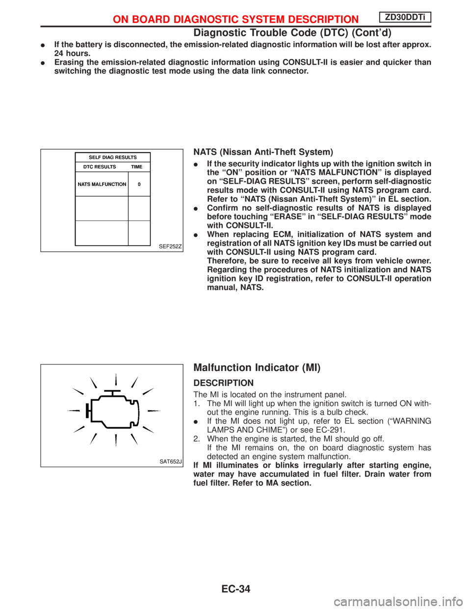
Malfunction Indicator (MI)
DESCRIPTION
The MI is located on the instrument panel.
1. The MI will light up when the ignition switch is turned ON with-
out the engine running. This is a bulb check.
IIf the MI does not light up, refer to EL section (ªWARNING
LAMPS AND CHIMEº) or see EC-291.
2. When the engine is started, the MI should go off.
If the MI remains on, the on board diagnostic system has
detected an engine system malfunction.
If MI illuminates or blinks irregularly after starting engine,
water may have accumulated in fuel filter. Drain water from
fuel filter. Refer to MA section.
SEF252Z
SAT652J
ON BOARD DIAGNOSTIC SYSTEM DESCRIPTIONZD30DDTi
Diagnostic Trouble Code (DTC) (Cont'd)
EC-34
Page 397 of 1767
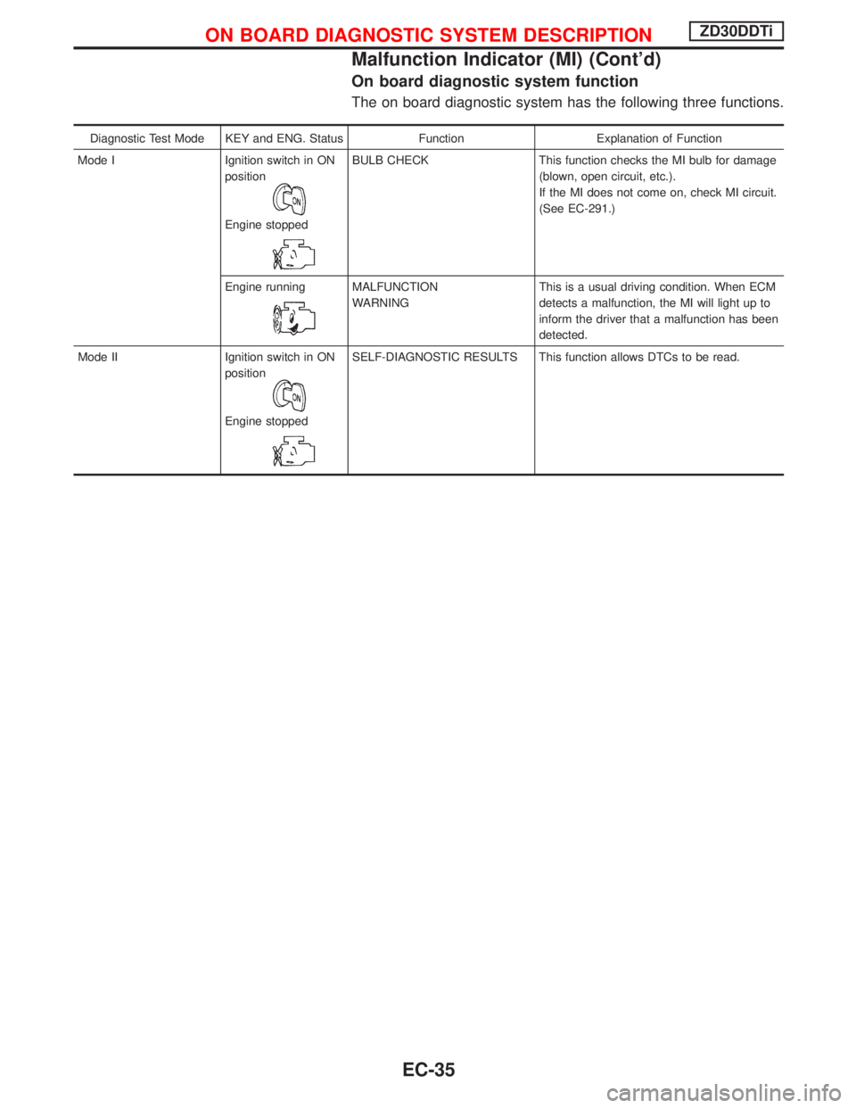
On board diagnostic system function
The on board diagnostic system has the following three functions.
Diagnostic Test Mode KEY and ENG. Status Function Explanation of Function
Mode I Ignition switch in ON
position
Engine stopped
BULB CHECK This function checks the MI bulb for damage
(blown, open circuit, etc.).
If the MI does not come on, check MI circuit.
(See EC-291.)
Engine running
MALFUNCTION
WARNINGThis is a usual driving condition. When ECM
detects a malfunction, the MI will light up to
inform the driver that a malfunction has been
detected.
Mode II Ignition switch in ON
position
Engine stopped
SELF-DIAGNOSTIC RESULTS This function allows DTCs to be read.
ON BOARD DIAGNOSTIC SYSTEM DESCRIPTIONZD30DDTi
Malfunction Indicator (MI) (Cont'd)
EC-35
Page 399 of 1767
Diagnostic test mode I Ð Bulb check
In this mode, the MI on the instrument panel should stay ON. If it remains OFF, check the bulb. Refer to EL
section, ªWARNING LAMPS AND CHIMEº or see EC-291.
Diagnostic test mode I Ð Malfunction warning
MI Condition
ON When the malfunction is detected or the ECM's CPU is malfunctioning.
OFF No malfunction.
Diagnostic test mode II Ð Self-diagnostic results
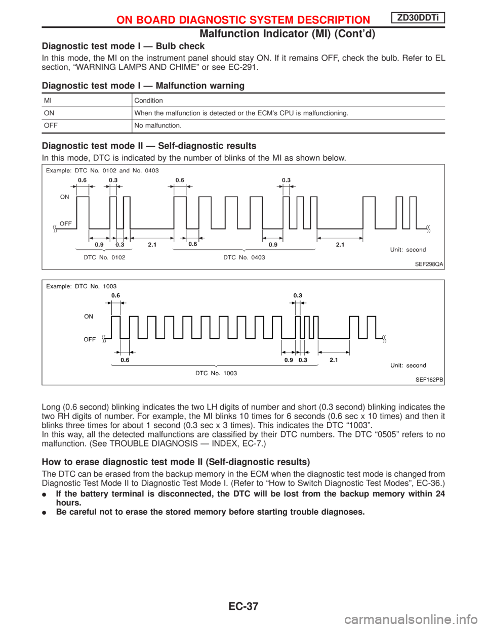
In this mode, DTC is indicated by the number of blinks of the MI as shown below.
Long (0.6 second) blinking indicates the two LH digits of number and short (0.3 second) blinking indicates the
two RH digits of number. For example, the MI blinks 10 times for 6 seconds (0.6 sec x 10 times) and then it
blinks three times for about 1 second (0.3 sec x 3 times). This indicates the DTC ª1003º.
In this way, all the detected malfunctions are classified by their DTC numbers. The DTC ª0505º refers to no
malfunction. (See TROUBLE DIAGNOSIS Ð INDEX, EC-7.)
How to erase diagnostic test mode II (Self-diagnostic results)
The DTC can be erased from the backup memory in the ECM when the diagnostic test mode is changed from
Diagnostic Test Mode II to Diagnostic Test Mode I. (Refer to ªHow to Switch Diagnostic Test Modesº, EC-36.)
IIf the battery terminal is disconnected, the DTC will be lost from the backup memory within 24
hours.
IBe careful not to erase the stored memory before starting trouble diagnoses.
SEF298QA
SEF162PB
ON BOARD DIAGNOSTIC SYSTEM DESCRIPTIONZD30DDTi
Malfunction Indicator (MI) (Cont'd)
EC-37
Page 684 of 1767
How to Erase DTC (Without CONSULT-II)
1. If the ignition switch stays ªONº after repair work, be sure to turn ignition switch ªOFFº once. Wait at least
5 seconds and then turn it ªONº (engine stopped) again.
2. Change the diagnostic test mode from Mode II to Mode I by using the data link connector. (See EC-323.)
The emission related diagnostic information in the ECM can be erased by changing the diagnostic test mode.
IIf the battery is disconnected, the emission-related diagnostic information will be lost after approx.
24 hours.
IErasing the emission-related diagnostic information using CONSULT-II is easier and quicker than
switching the diagnostic test mode using the data link connector.
Malfunction Indicator (MI)
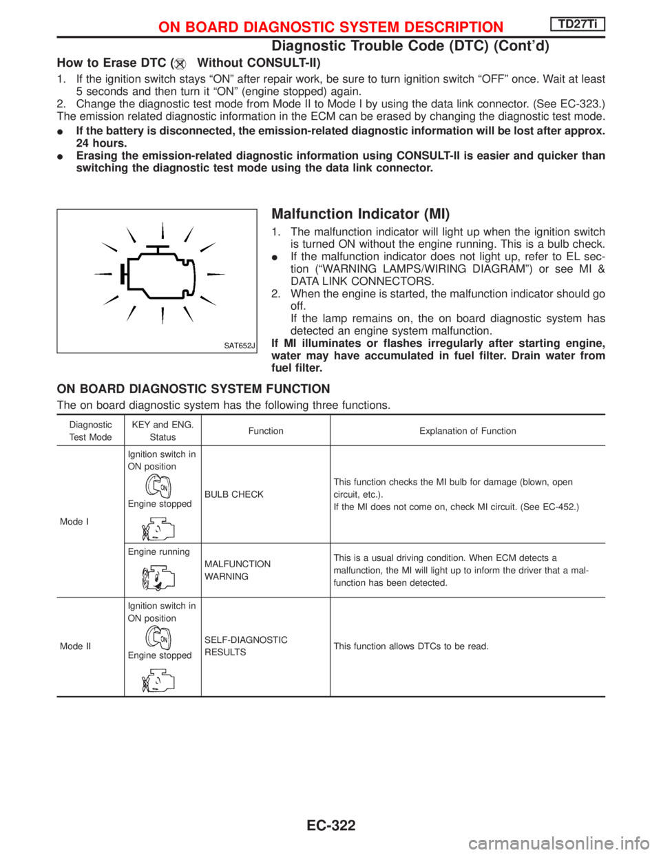
1. The malfunction indicator will light up when the ignition switch
is turned ON without the engine running. This is a bulb check.
IIf the malfunction indicator does not light up, refer to EL sec-
tion (ªWARNING LAMPS/WIRING DIAGRAMº) or see MI &
DATA LINK CONNECTORS.
2. When the engine is started, the malfunction indicator should go
off.
If the lamp remains on, the on board diagnostic system has
detected an engine system malfunction.
If MI illuminates or flashes irregularly after starting engine,
water may have accumulated in fuel filter. Drain water from
fuel filter.
ON BOARD DIAGNOSTIC SYSTEM FUNCTION
The on board diagnostic system has the following three functions.
Diagnostic
Test ModeKEY and ENG.
StatusFunction Explanation of Function
Mode IIgnition switch in
ON position
Engine stoppedBULB CHECKThis function checks the MI bulb for damage (blown, open
circuit, etc.).
If the MI does not come on, check MI circuit. (See EC-452.)
Engine running
MALFUNCTION
WARNINGThis is a usual driving condition. When ECM detects a
malfunction, the MI will light up to inform the driver that a mal-
function has been detected.
Mode IIIgnition switch in
ON position
Engine stopped
SELF-DIAGNOSTIC
RESULTSThis function allows DTCs to be read.
SAT652J
ON BOARD DIAGNOSTIC SYSTEM DESCRIPTIONTD27Ti
Diagnostic Trouble Code (DTC) (Cont'd)
EC-322
Page 686 of 1767
DIAGNOSTIC TEST MODE IÐBULB CHECK
In this mode, the MALFUNCTION INDICATOR on the instrument panel should stay ON. If it remains OFF,
check the bulb. Refer to EL section (ªWARNING LAMPS/WIRING DIAGRAMº) or see EC-452.
DIAGNOSTIC TEST MODE IÐMALFUNCTION WARNING
MI Condition
ON When a malfunction is detected or the ECM's CPU is malfunctioning.
OFF No malfunction.
IThese Diagnostic Trouble Code Numbers are clarified in Diagnostic Test Mode II (SELF-DIAGNOSTIC
RESULTS).
DIAGNOSTIC TEST MODE IIÐSELF-DIAGNOSTIC RESULTS
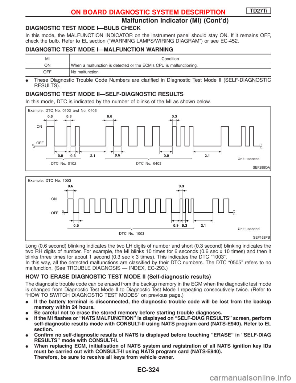
In this mode, DTC is indicated by the number of blinks of the MI as shown below.
Long (0.6 second) blinking indicates the two LH digits of number and short (0.3 second) blinking indicates the
two RH digits of number. For example, the MI blinks 10 times for 6 seconds (0.6 sec x 10 times) and then it
blinks three times for about 1 second (0.3 sec x 3 times). This indicates the DTC ª1003º.
In this way, all the detected malfunctions are classified by their DTC numbers. The DTC ª0505º refers to no
malfunction. (See TROUBLE DIAGNOSIS Ð INDEX, EC-293.)
HOW TO ERASE DIAGNOSTIC TEST MODE II (Self-diagnostic results)
The diagnostic trouble code can be erased from the backup memory in the ECM when the diagnostic test mode
is changed from Diagnostic Test Mode II to Diagnostic Test Mode I repeating consecutively twice. (Refer to
ªHOW TO SWITCH DIAGNOSTIC TEST MODESº on previous page.)
IIf the battery terminal is disconnected, the diagnostic trouble code will be lost from the backup
memory within 24 hours.
IBe careful not to erase the stored memory before starting trouble diagnoses.
IIf the MI flashes or ªNATS MALFUNCTIONº is displayed on ªSELF-DIAG RESULTSº screen, perform
self-diagnostic results mode with CONSULT-II using NATS program card (NATS-E940). Refer to EL
section.
IConfirm no self-diagnostic results of NATS is displayed before touching ªERASEº in ªSELF-DIAG
RESULTSº mode with CONSULT-II.
IWhen replacing ECM, initialisation of NATS system and registration of all NATS ignition key IDs
must be carried out with CONSULT-II using NATS program card (NATS-E940).
Therefore, be sure to receive all keys from vehicle owner.
SEF298QA
SEF162PB
ON BOARD DIAGNOSTIC SYSTEM DESCRIPTIONTD27Ti
Malfunction Indicator (MI) (Cont'd)
EC-324
Page 766 of 1767
Component Description
Malfunction Indicator (MI) is located on the instrument panel. When the ignition switch is turned ON without
engine running, MI will light up. This is a bulb check. When the engine is started, MI should go off. If MI remains
on, the on board diagnostic system has detected an engine system malfunction.
On Board Diagnosis Logic
DTC No. Trouble diagnosis name DTC detecting condition Possible cause
P0650
0907Malfunction indicator (MI) control cir-
cuitIAn excessively high voltage is sent
to ECM through the MI circuit
under the condition that calls for MI
light up.
IAn excessively low voltage is sent
to ECM through the MI circuit
under the condition that calls for MI
not to light up.IHarness or connectors
(MI circuit is open or shorted.)
IMI
DTC Confirmation Procedure
NOTE:
If ªDTC Confirmation Procedureº has been previously
conducted, always turn ignition switch ªOFFº and wait at least
10 seconds before conducting the next test.
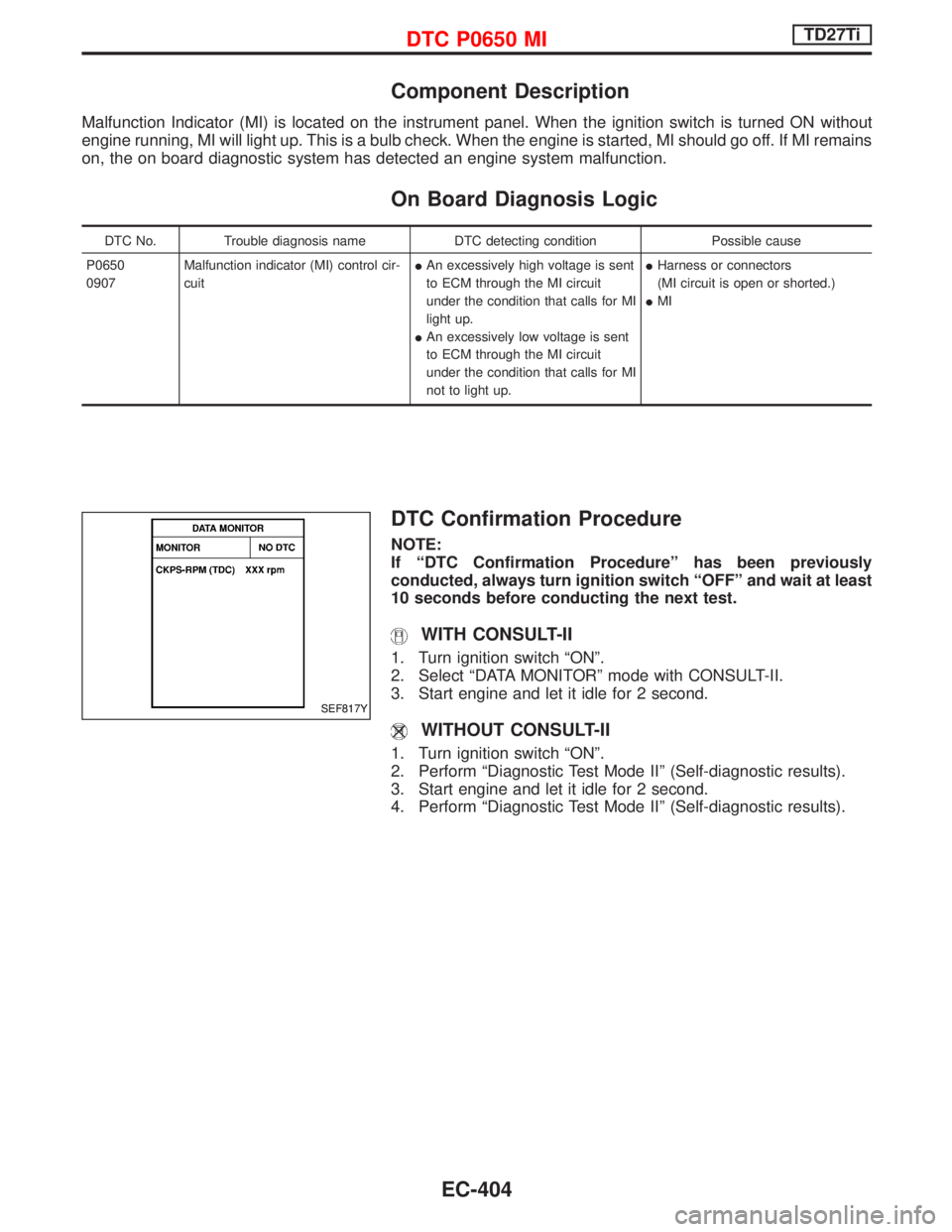
WITH CONSULT-II
1. Turn ignition switch ªONº.
2. Select ªDATA MONITORº mode with CONSULT-II.
3. Start engine and let it idle for 2 second.
WITHOUT CONSULT-II
1. Turn ignition switch ªONº.
2. Perform ªDiagnostic Test Mode IIº (Self-diagnostic results).
3. Start engine and let it idle for 2 second.
4. Perform ªDiagnostic Test Mode IIº (Self-diagnostic results).
SEF817Y
DTC P0650 MITD27Ti
EC-404
Page 817 of 1767

ELECTRICAL SYSTEM
SECTION
EL
When you read wiring diagrams:
IRead GI section, ªHOW TO READ WIRING DIAGRAMSº.
CONTENTS
HARNESS CONNECTOR................................................3
Description ...................................................................3
STANDARDIZED RELAYS..............................................4
Description ...................................................................4
POWER SUPPLY ROUTING...........................................6
Schematic ....................................................................6
Wiring Diagram - POWER - ........................................8
Fuse ...........................................................................17
Fusible Link................................................................17
Circuit Breaker Inspection .........................................17
GROUND DISTRIBUTION.............................................18
COMBINATION SWITCH...............................................23
Check .........................................................................23
Replacement ..............................................................24
STEERING SWITCH......................................................25
Check .........................................................................25
HEADLAMP - Without Daytime Light System -.........26
Wiring Diagram - H/LAMP -.......................................26
HEADLAMP - Daytime Light System -.......................29
Operation ...................................................................29
Schematic ..................................................................30
Wiring Diagram - DTRL - ...........................................31
HEADLAMP - Headlamp Aiming Control -.................37
Description .................................................................37
Replacing Headlamp Aiming Actuator .......................38
Wiring Diagram - H/AIM - ..........................................39
Trouble Diagnoses.....................................................42
HEADLAMP...................................................................43
Bulb Replacement .....................................................43
Aiming Adjustment .....................................................43
EXTERIOR LAMP..........................................................45
Wiring Diagram - TAIL/L - ..........................................45
Wiring Diagram - STOP/L - .......................................48
Wiring Diagram - BACK/L - .......................................49
Wiring Diagram - F/FOG - .........................................51
Front Fog Lamp Aiming Adjustment ..........................53
Wiring Diagram - R/FOG -.........................................54
Schematic ..................................................................55Wiring Diagram - TURN - ..........................................56
Bulb Specifications ....................................................60
INTERIOR LAMP...........................................................61
Schematic ..................................................................61
Wiring Diagram - ILL - ...............................................62
Wiring Diagram - INT/L - ...........................................66
METER AND GAUGES.................................................70
Combination Meter ....................................................70
Schematic ..................................................................71
Wiring Diagram - METER - .......................................72
Combination Meter Self-Diagnosis ............................76
Components Inspection .............................................78
Trouble Diagnoses.....................................................79
Fuel Tank Gauge Unit Check ....................................80
Thermal Transmitter Check .......................................80
Oil Pressure Switch Check ........................................80
WARNING LAMPS AND CHIME...................................81
Schematic ..................................................................81
Wiring Diagram - WARN - .........................................82
Diode Check ..............................................................92
Wiring Diagram - CHIME - ........................................93
WIPER AND WASHER..................................................94
Wiring Diagram - WIPER - ........................................94
Wiring Diagram - WIP/R -..........................................96
Installation ..................................................................98
Washer Nozzle Adjustment .......................................99
Check Valve ...............................................................99
Wiring Diagram - HLC - ...........................................100
HORN, CIGARETTE LIGHTER AND CLOCK............104
Wiring Diagram - HORN - .......................................104
Wiring Diagram - CIGAR -.......................................105
Wiring Diagram - CLOCK -......................................106
REAR WINDOW DEFOGGER AND DOOR
MIRROR DEFOGGER.................................................107
Wiring Diagram - DEF - ...........................................107
Filament Check ........................................................109
Filament Repair ....................................................... 110
AUDIO.......................................................................... 111
Page 859 of 1767
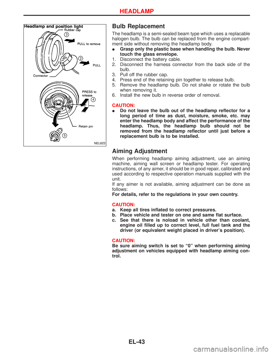
Bulb Replacement
The headlamp is a semi-sealed beam type which uses a replacable
halogen bulb. The bulb can be replaced from the engine compart-
ment side without removing the headlamp body.
IGrasp only the plastic base when handling the bulb. Never
touch the glass envelope.
1. Disconnect the battery cable.
2. Disconnect the harness connector from the back side of the
bulb.
3. Pull off the rubber cap.
4. Press end of the retaining pin together to release bulb.
5. Remove the headlamp bulb. Do not shake or rotate the bulb
when removing it.
6. Install the new bulb in reverse order of removal.
CAUTION:
IDo not leave the bulb out of the headlamp reflector for a
long period of time as dust, moisture, smoke, etc. may
enter the headlamp body and affect the performance of the
headlamp. Thus, the headlamp bulb should not be
removed from the headlamp reflector until just before a
replacement bulb is to be installed.
Aiming Adjustment
When performing headlamp aiming adjustment, use an aiming
machine, aiming wall screen or headlamp tester. For operating
instructions, of any aimer, it should be in good repair, calibrated and
used according to respective operation manuals supplied with the
unit.
If any aimer is not available, aiming adjustment can be done as
follows:
For details, refer to the regulations in your own country.
CAUTION:
a. Keep all tires inflated to correct pressures.
b. Place vehicle and tester on one and same flat surface.
c. See that there is noload in vehicle other than coolant,
engine oil filled up to correct level, full fuel tank and the
driver (or equivalent weight placed in driver's position).
CAUTION:
Be sure aiming switch is set to ª0º when performing aiming
adjustment on vehicles equipped with headlamp aiming con-
trol.
NEL623
HEADLAMP
EL-43