sport mode NISSAN TERRANO 2002 Service Repair Manual
[x] Cancel search | Manufacturer: NISSAN, Model Year: 2002, Model line: TERRANO, Model: NISSAN TERRANO 2002Pages: 1767, PDF Size: 41.51 MB
Page 7 of 1767
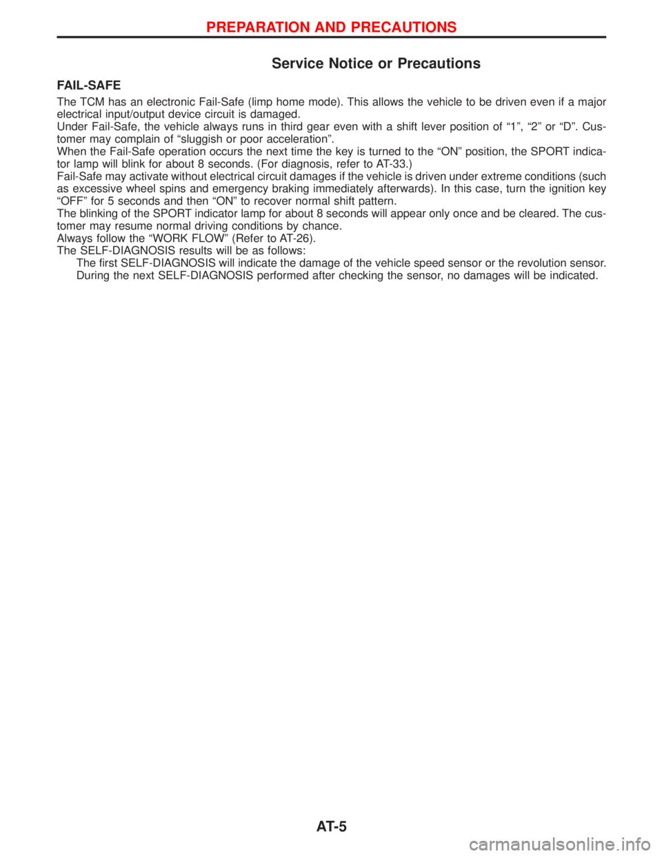
Service Notice or Precautions
FAIL-SAFE
The TCM has an electronic Fail-Safe (limp home mode). This allows the vehicle to be driven even if a major
electrical input/output device circuit is damaged.
Under Fail-Safe, the vehicle always runs in third gear even with a shift lever position of ª1º, ª2º or ªDº. Cus-
tomer may complain of ªsluggish or poor accelerationº.
When the Fail-Safe operation occurs the next time the key is turned to the ªONº position, the SPORT indica-
tor lamp will blink for about 8 seconds. (For diagnosis, refer to AT-33.)
Fail-Safe may activate without electrical circuit damages if the vehicle is driven under extreme conditions (such
as excessive wheel spins and emergency braking immediately afterwards). In this case, turn the ignition key
ªOFFº for 5 seconds and then ªONº to recover normal shift pattern.
The blinking of the SPORT indicator lamp for about 8 seconds will appear only once and be cleared. The cus-
tomer may resume normal driving conditions by chance.
Always follow the ªWORK FLOWº (Refer to AT-26).
The SELF-DIAGNOSIS results will be as follows:
The first SELF-DIAGNOSIS will indicate the damage of the vehicle speed sensor or the revolution sensor.
During the next SELF-DIAGNOSIS performed after checking the sensor, no damages will be indicated.
PREPARATION AND PRECAUTIONS
AT- 5
Page 13 of 1767
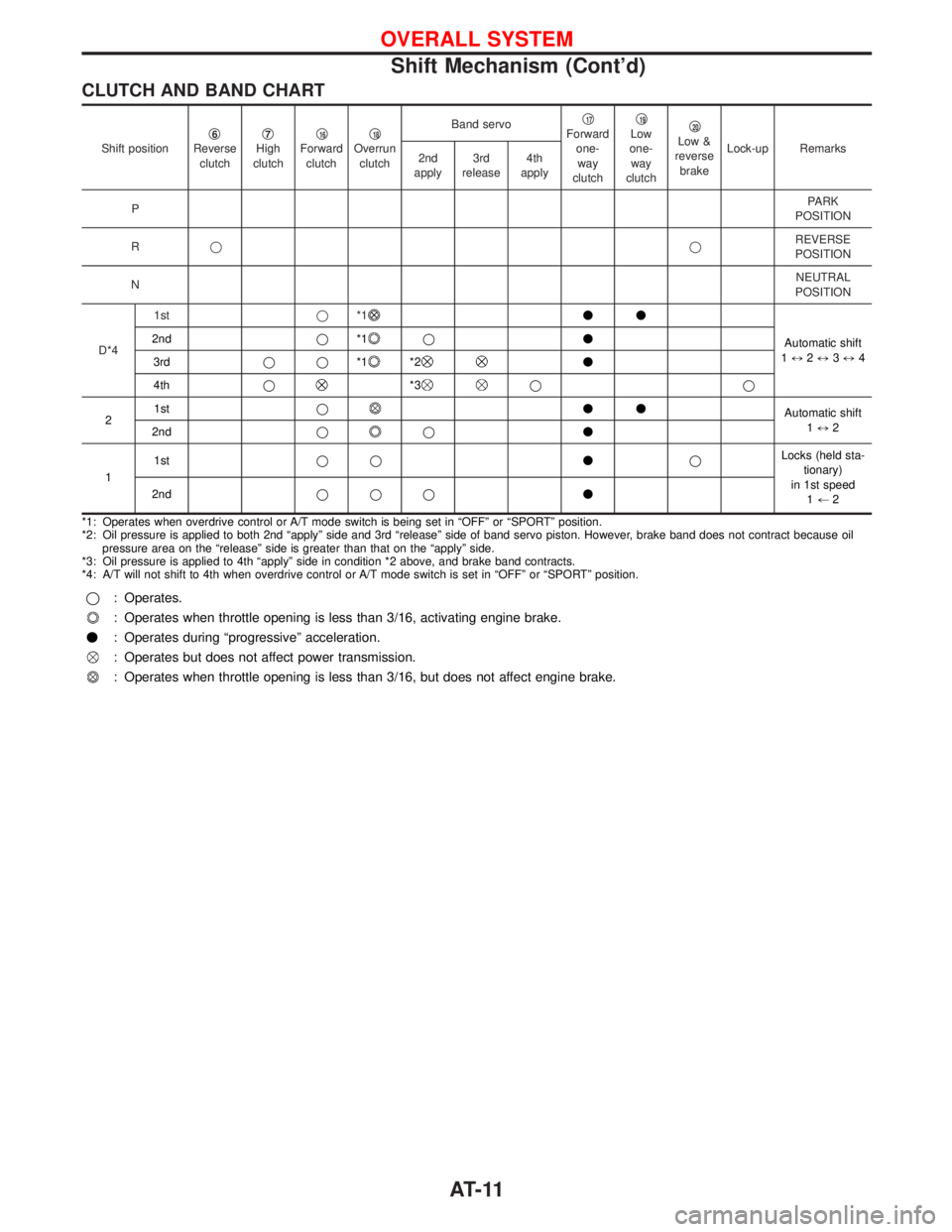
CLUTCH AND BAND CHART
Shift positionq6Reverse
clutchq7High
clutchq16Forward
clutchq18Overrun
clutchBand servoq
17Forward
one-
way
clutchq19Low
one-
way
clutchq20Low &
reverse
brakeLock-up Remarks
2nd
apply3rd
release4th
apply
PPARK
POSITION
RqqREVERSE
POSITION
NNEUTRAL
POSITION
D*41stq*1
vv
Automatic shift
1)2)3)4 2ndq*1
qv
3rdqq*1
*2v
4thq
*3qq
21stq
vv
Automatic shift
1)2
2ndq
qv
11stqqvqLocks (held sta-
tionary)
in 1st speed
1+2 2ndqqqv
*1: Operates when overdrive control or A/T mode switch is being set in ªOFFº or ªSPORTº position.
*2: Oil pressure is applied to both 2nd ªapplyº side and 3rd ªreleaseº side of band servo piston. However, brake band does not contract because oil
pressure area on the ªreleaseº side is greater than that on the ªapplyº side.
*3: Oil pressure is applied to 4th ªapplyº side in condition *2 above, and brake band contracts.
*4: A/T will not shift to 4th when overdrive control or A/T mode switch is set in ªOFFº or ªSPORTº position.
q: Operates.
: Operates when throttle opening is less than 3/16, activating engine brake.
v: Operates during ªprogressiveº acceleration.
: Operates but does not affect power transmission.
: Operates when throttle opening is less than 3/16, but does not affect engine brake.
OVERALL SYSTEM
Shift Mechanism (Cont'd)
AT-11
Page 14 of 1767
Control System
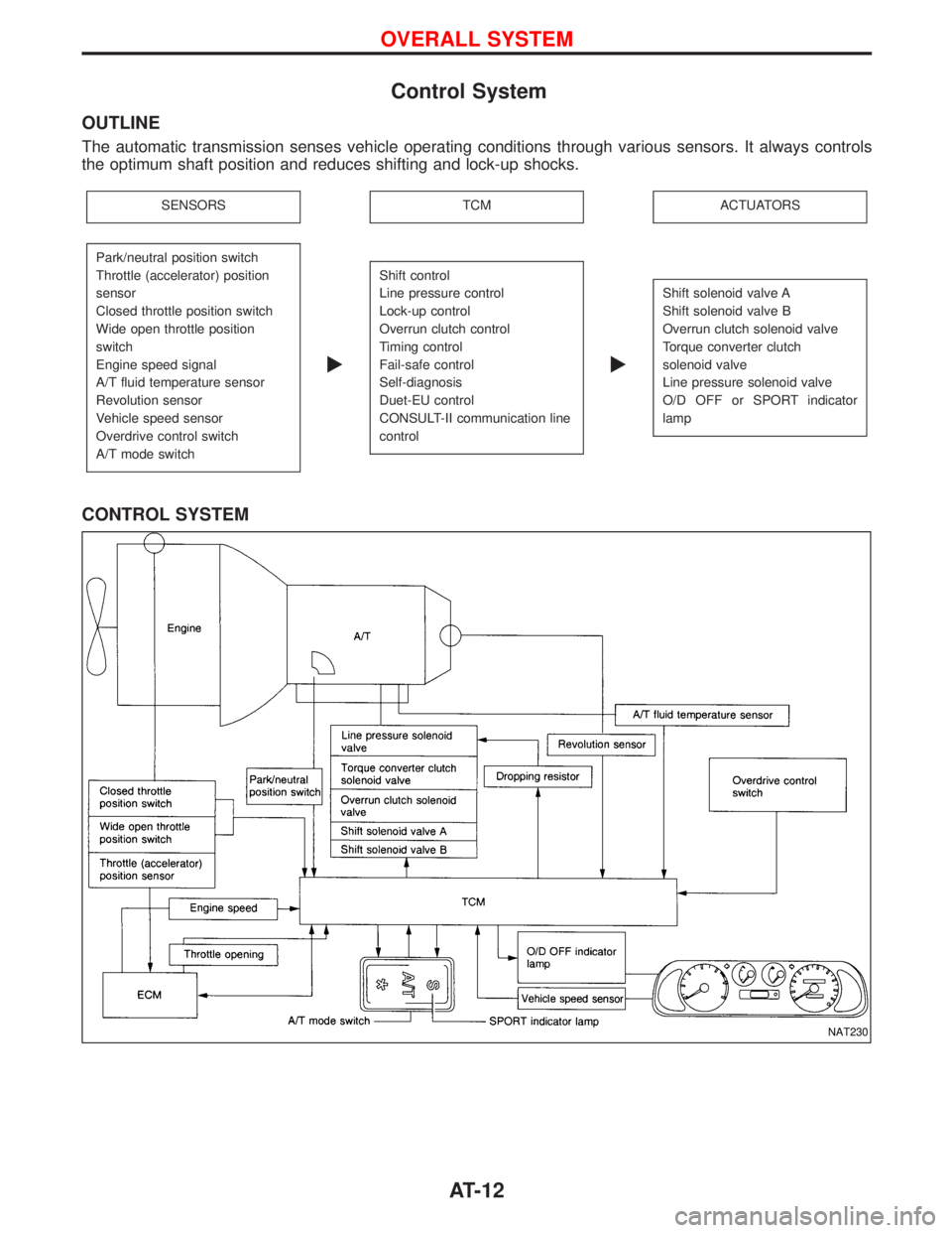
OUTLINE
The automatic transmission senses vehicle operating conditions through various sensors. It always controls
the optimum shaft position and reduces shifting and lock-up shocks.
SENSORSTCMACTUATORS
Park/neutral position switch
Throttle (accelerator) position
sensor
Closed throttle position switch
Wide open throttle position
switch
Engine speed signal
A/T fluid temperature sensor
Revolution sensor
Vehicle speed sensor
Overdrive control switch
A/T mode switch
E
Shift control
Line pressure control
Lock-up control
Overrun clutch control
Timing control
Fail-safe control
Self-diagnosis
Duet-EU control
CONSULT-II communication line
control
E
Shift solenoid valve A
Shift solenoid valve B
Overrun clutch solenoid valve
Torque converter clutch
solenoid valve
Line pressure solenoid valve
O/D OFF or SPORT indicator
lamp
CONTROL SYSTEM
NAT230
OVERALL SYSTEM
AT-12
Page 15 of 1767
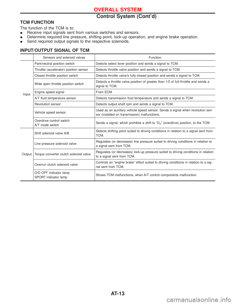
TCM FUNCTION
The function of the TCM is to:
IReceive input signals sent from various switches and sensors.
IDetermine required line pressure, shifting point, lock-up operation, and engine brake operation.
ISend required output signals to the respective solenoids.
INPUT/OUTPUT SIGNAL OF TCM
Sensors and solenoid valves Function
InputPark/neutral position switch Detects select lever position and sends a signal to TCM.
Throttle (accelerator) position sensor Detects throttle valve position and sends a signal to TCM.
Closed throttle position switch Detects throttle valve's fully-closed position and sends a signal to TCM.
Wide open throttle position switchDetects a throttle valve position of greater than 1/2 of full throttle and sends a
signal to TCM.
Engine speed signal From ECM.
A/T fluid temperature sensor Detects transmission fluid temperature and sends a signal to TCM.
Revolution sensor Detects output shaft rpm and sends a signal to TCM.
Vehicle speed sensorUsed as an auxiliary vehicle speed sensor. Sends a signal when revolution sen-
sor (installed on transmission) malfunctions.
Overdrive control switch
A/T mode switchSends a signal, which prohibits a shift to ªD
4º (overdrive) position, to the TCM.
OutputShift solenoid valve A/BSelects shifting point suited to driving conditions in relation to a signal sent from
TCM.
Line pressure solenoid valveRegulates (or decreases) line pressure suited to driving conditions in relation to
a signal sent from TCM.
Torque converter clutch solenoid valveRegulates (or decreases) lock-up pressure suited to driving conditions in relation
to a signal sent from TCM.
Overrun clutch solenoid valveControls an ªengine brakeº effect suited to driving conditions in relation to a sig-
nal sent from TCM.
O/D OFF indicator lamp
SPORT indicator lampShows TCM malfunctions, when A/T control components malfunction.
OVERALL SYSTEM
Control System (Cont'd)
AT-13
Page 17 of 1767
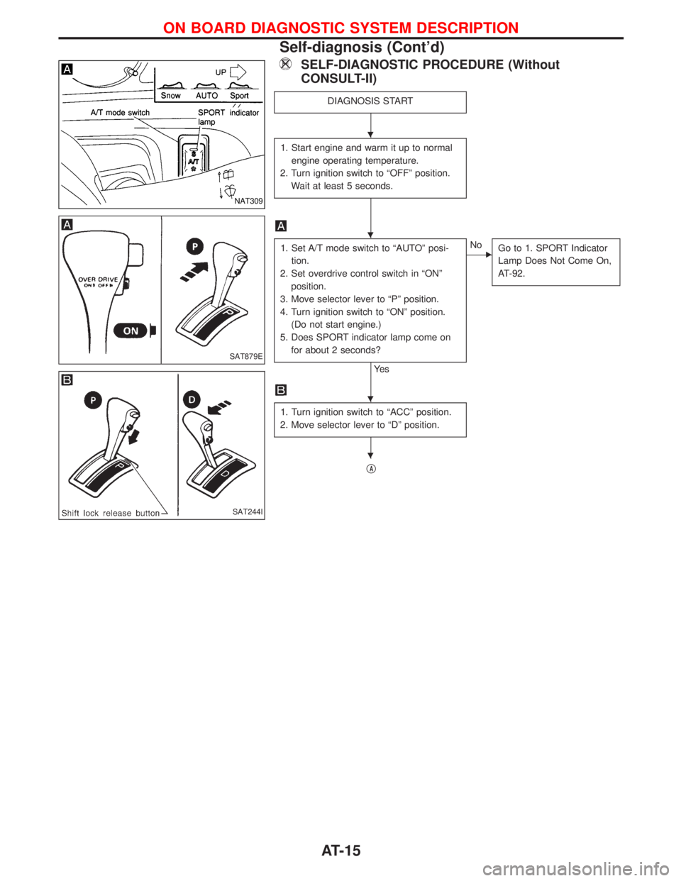
SELF-DIAGNOSTIC PROCEDURE (Without
CONSULT-II)
DIAGNOSIS START
1. Start engine and warm it up to normal
engine operating temperature.
2. Turn ignition switch to ªOFFº position.
Wait at least 5 seconds.
1. Set A/T mode switch to ªAUTOº posi-
tion.
2. Set overdrive control switch in ªONº
position.
3. Move selector lever to ªPº position.
4. Turn ignition switch to ªONº position.
(Do not start engine.)
5. Does SPORT indicator lamp come on
for about 2 seconds?
Ye s
ENo
Go to 1. SPORT Indicator
Lamp Does Not Come On,
AT-92.
1. Turn ignition switch to ªACCº position.
2. Move selector lever to ªDº position.
qA
NAT309
SAT879E
SAT244I
H
H
H
H
ON BOARD DIAGNOSTIC SYSTEM DESCRIPTION
Self-diagnosis (Cont'd)
AT-15
Page 23 of 1767
![NISSAN TERRANO 2002 Service Repair Manual Item DisplayMonitor item
Description Remarks ECU
input
signalsMain
signals
ASCD-OD cut signal ASCD×OD CUT
[ON/OFF]
XÐIStatus of ASCD×OD release signal is
displayed.
ON ... OD released
OFF ... OD no](/img/5/57393/w960_57393-22.png "NISSAN TERRANO 2002 Service Repair Manual Item DisplayMonitor item
Description Remarks ECU
input
signalsMain
signals
ASCD-OD cut signal ASCD×OD CUT
[ON/OFF]
XÐIStatus of ASCD×OD release signal is
displayed.
ON ... OD released
OFF ... OD no")
Item DisplayMonitor item
Description Remarks ECU
input
signalsMain
signals
ASCD-OD cut signal ASCD×OD CUT
[ON/OFF]
XÐIStatus of ASCD×OD release signal is
displayed.
ON ... OD released
OFF ... OD not releasedIThis is displayed even when no
ASCD is mounted.
Kickdown switch KICKDOWN SW
[ON/OFF]XÐION/OFF status, computed from sig-
nal of kickdown SW, is displayed.IThis is displayed even when no
kickdown switch is equipped.
A/T mode switch POWER SHIFT SW
[ON/OFF]XÐION/OFF state computed from signal
of SPORT shift SW is displayed.
Closed throttle position
switchCLOSED THL/SW
[ON/OFF] X ÐION/OFF status, computed from sig-
nal of closed throttle (accelerator)
position SW, is displayed.
Wide open throttle posi-
tion switchW/O THRL/P-SW
[ON/OFF] X ÐION/OFF status, computed from sig-
nal of wide open throttle (accelera-
tor) position SW, is displayed.
A/T mode switch HOLD SW
[ON/OFF]XÐION/OFF status, computed from sig-
nal of SNOW shift SW, is displayed.
Gear position GEAR
ÐXIGear position data used for compu-
tation by TCM, is displayed.
Selector lever position SLCT LVR POSI
ÐXISelector lever position data, used
for computation by TCM, is dis-
played.IA specific value used for control is
displayed if fail-safe is activated due
to error.
Vehicle speed VEHICLE SPEED
[km/h] or [mph]ÐXIVehicle speed data, used for com-
putation by TCM, is displayed.
Throttle (accelerator)
positionTHROTTLE POSI
[/8] Ð XIThrottle (accelerator) position data,
used for computation by TCM, is
displayed.IA specific value used for control is
displayed if fail-safe is activated due
to error.
Line pressure duty LINE PRES DTY
[%] Ð XIControl value of line pressure sole-
noid valve, computed by TCM from
each input signal, is displayed.
Torque converter clutch
solenoid valve dutyTCC S/V DUTY
[%]
ÐXIControl value of torque converter
clutch solenoid valve, computed by
TCM from each input signal, is dis-
played.
Shift solenoid valve A SHIFT S/V A
[ON/OFF] Ð XIControl value of shift solenoid valve
A, computed by TCM from each
input signal, is displayed.Control value of solenoid is displayed
even if solenoid circuit is discon-
nected.
The ªOFFº signal is displayed if sole-
noid circuit is shorted. Shift solenoid valve B SHIFT S/V B
[ON/OFF] Ð XIControl value of shift solenoid valve
B, computed by TCM from each
input signal, is displayed.
Overrun clutch solenoid
valveOVERRUN/C S/V
[ON/OFF] Ð XIControl value of overrun clutch sole-
noid valve computed by TCM from
each input signal is displayed.
Self-diagnosis display
lamp
(SPORT indicator lamp)SELF-D DP LMP
[ON/OFF] Ð XIControl status of SPORT indicator
lamp is displayed.
X: Applicable
Ð: Not applicable
ON BOARD DIAGNOSTIC SYSTEM DESCRIPTION
Diagnosis by CONSULT-II (Cont'd)
AT-21
Page 25 of 1767
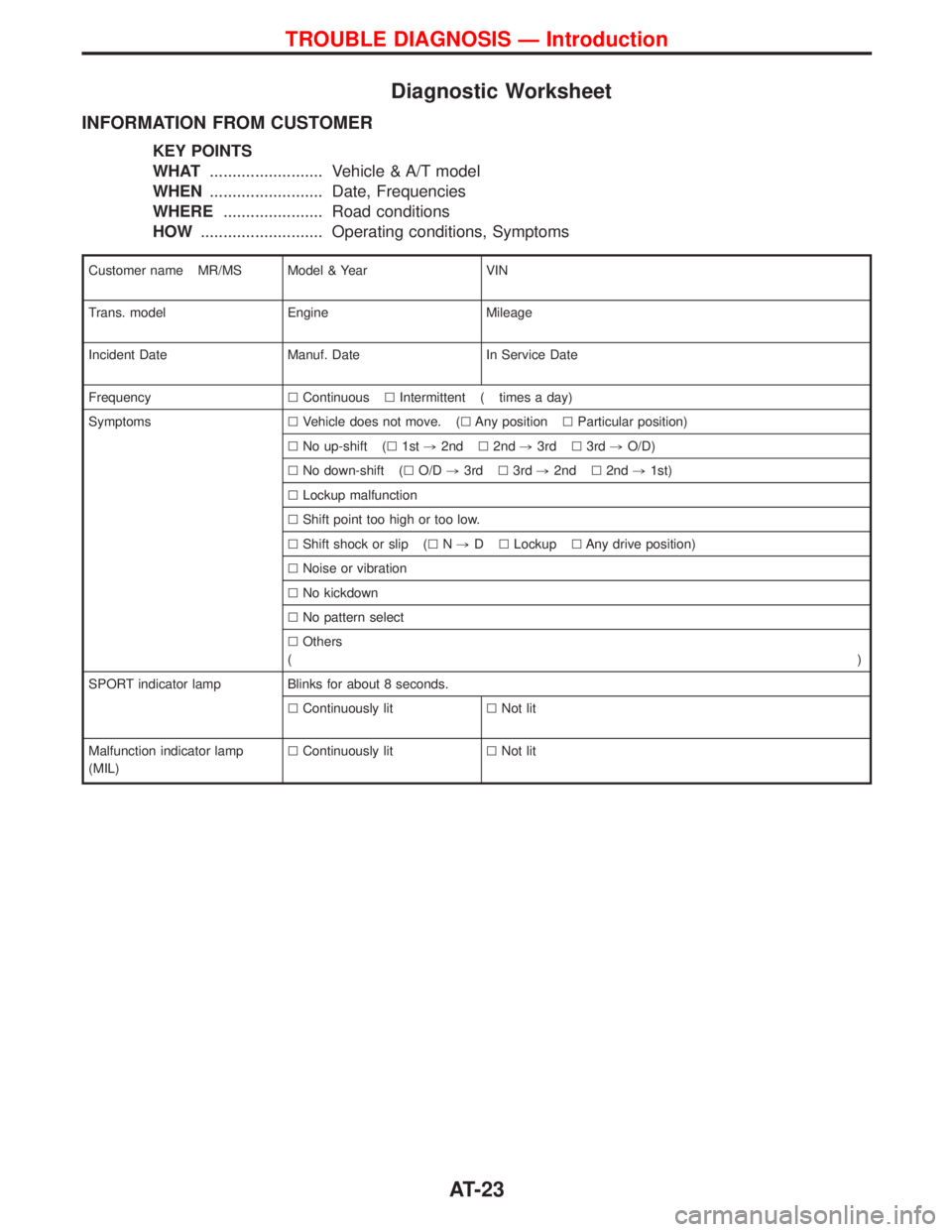
Diagnostic Worksheet
INFORMATION FROM CUSTOMER
KEY POINTS
WHAT......................... Vehicle & A/T model
WHEN......................... Date, Frequencies
WHERE...................... Road conditions
HOW........................... Operating conditions, Symptoms
Customer name MR/MS Model & Year VIN
Trans. model Engine Mileage
Incident Date Manuf. Date In Service Date
FrequencylContinuouslIntermittent ( times a day)
SymptomslVehicle does not move. (lAny positionlParticular position)
lNo up-shift (l1st,2ndl2nd,3rdl3rd,O/D)
lNo down-shift (lO/D,3rdl3rd,2ndl2nd,1st)
lLockup malfunction
lShift point too high or too low.
lShift shock or slip (lN,DlLockuplAny drive position)
lNoise or vibration
lNo kickdown
lNo pattern select
lOthers
()
SPORT indicator lamp Blinks for about 8 seconds.
lContinuously litlNot lit
Malfunction indicator lamp
(MIL)lContinuously litlNot lit
TROUBLE DIAGNOSIS Ð Introduction
AT-23
Page 35 of 1767
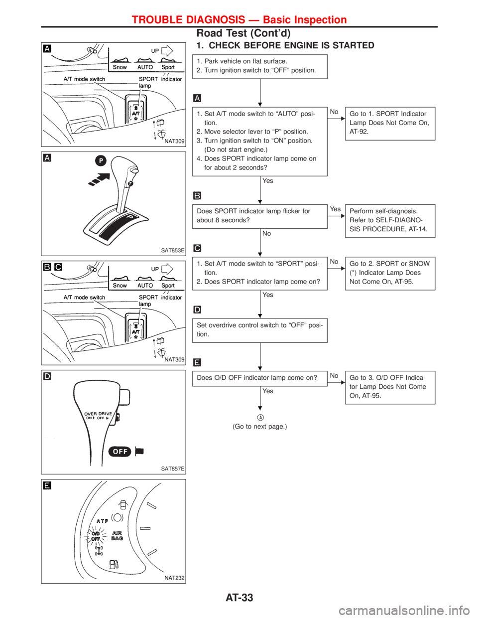
1. CHECK BEFORE ENGINE IS STARTED
1. Park vehicle on flat surface.
2. Turn ignition switch to ªOFFº position.
1. Set A/T mode switch to ªAUTOº posi-
tion.
2. Move selector lever to ªPº position.
3. Turn ignition switch to ªONº position.
(Do not start engine.)
4. Does SPORT indicator lamp come on
for about 2 seconds?
Ye s
ENo
Go to 1. SPORT Indicator
Lamp Does Not Come On,
AT-92.
Does SPORT indicator lamp flicker for
about 8 seconds?
No
EYe s
Perform self-diagnosis.
Refer to SELF-DIAGNO-
SIS PROCEDURE, AT-14.
1. Set A/T mode switch to ªSPORTº posi-
tion.
2. Does SPORT indicator lamp come on?
Ye s
ENo
Go to 2. SPORT or SNOW
(*) Indicator Lamp Does
Not Come On, AT-95.
Set overdrive control switch to ªOFFº posi-
tion.
Does O/D OFF indicator lamp come on?
Ye s
ENo
Go to 3. O/D OFF Indica-
tor Lamp Does Not Come
On, AT-95.
qA
(Go to next page.)
NAT309
SAT853E
NAT309
SAT857E
NAT232
H
H
H
H
H
H
TROUBLE DIAGNOSIS Ð Basic Inspection
Road Test (Cont'd)
AT-33
Page 36 of 1767
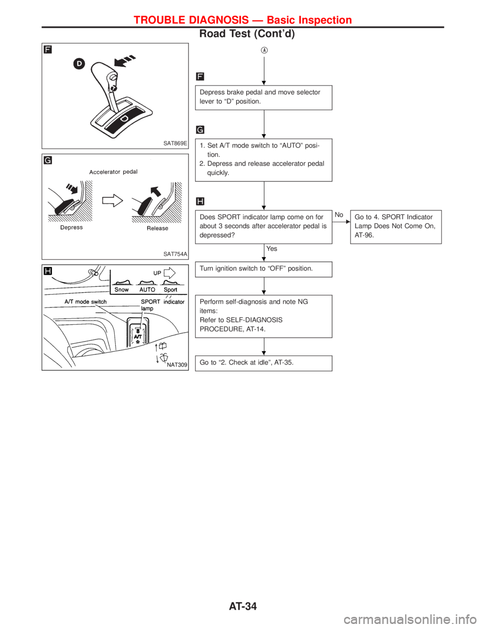
qA
Depress brake pedal and move selector
lever to ªDº position.
1. Set A/T mode switch to ªAUTOº posi-
tion.
2. Depress and release accelerator pedal
quickly.
Does SPORT indicator lamp come on for
about 3 seconds after accelerator pedal is
depressed?
Ye s
ENo
Go to 4. SPORT Indicator
Lamp Does Not Come On,
AT-96.
Turn ignition switch to ªOFFº position.
Perform self-diagnosis and note NG
items:
Refer to SELF-DIAGNOSIS
PROCEDURE, AT-14.
Go to ª2. Check at idleº, AT-35.
SAT869E
SAT754A
NAT309
H
H
H
H
H
H
TROUBLE DIAGNOSIS Ð Basic Inspection
Road Test (Cont'd)
AT-34
Page 50 of 1767
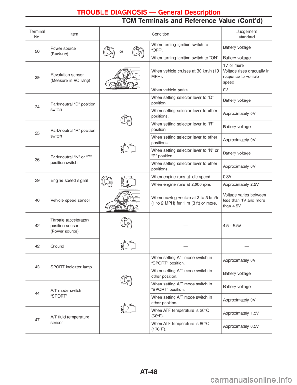
Terminal
No.Item ConditionJudgement
standard
28Power source
(Back-up)
or
When turning ignition switch to
ªOFFº.Battery voltage
When turning ignition switch to ªONº. Battery voltage
29Revolution sensor
(Measure in AC rang)
When vehicle cruises at 30 km/h (19
MPH).1V or more
Voltage rises gradually in
response to vehicle
speed.
When vehicle parks. 0V
34Park/neutral ªDº position
switch
When setting selector lever to ªDº
position.Battery voltage
When setting selector lever to other
positions.Approximately 0V
35Park/neutral ªRº position
switchWhen setting selector lever to ªRº
position.Battery voltage
When setting selector lever to other
positions.Approximately 0V
36Park/neutral ªNº or ªPº
position switchWhen setting selector lever to ªNº or
ªPº position.Battery voltage
When setting selector lever to other
positions.Approximately 0V
39 Engine speed signal
When engine runs at idle speed. 0.8V
When engine runs at 2,000 rpm. Approximately 2.2V
40 Vehicle speed sensor
When moving vehicle at 2 to 3 km/h
(1 to 2 MPH) for1m(3ft)ormore.Voltage varies between
less than 1V and more
than 4.5V
42Throttle (accelerator)
position sensor
(Power source)
Ð 4.5 - 5.5V
42 Ground Ð Ð
43 SPORT indicator lamp
When setting A/T mode switch in
ªSPORTº position.Approximately 0V
When setting A/T mode switch in
other position.Battery voltage
44A/T mode switch
ªSPORTºWhen setting A/T mode switch in
ªSPORTº position.Battery voltage
When setting A/T mode switch in
other position.Approximately 0V
47A/T fluid temperature
sensorWhen ATF temperature is 20ÉC
(68ÉF).Approximately 1.5V
When ATF temperature is 80ÉC
(176ÉF).Approximately 0.5V
TROUBLE DIAGNOSIS Ð General Description
TCM Terminals and Reference Value (Cont'd)
AT-48