Air conditioning NISSAN TERRANO 2004 Service Repair Manual
[x] Cancel search | Manufacturer: NISSAN, Model Year: 2004, Model line: TERRANO, Model: NISSAN TERRANO 2004Pages: 1833, PDF Size: 53.42 MB
Page 276 of 1833
ENGINE CONTROL SYSTEMSECTION
EC
CONTENTS
ZD30DDTi
TROUBLE DIAGNOSIS - INDEX ....................................7
Alphabetical & Numerical Index for DTC ....................7
PRECAUTIONS ...............................................................9
Precautions ..................................................................9
ENGINE AND EMISSION CONTROL OVERALL
SYSTEM ........................................................................\
.12
Engine Control Component Parts Location ...............12
Circuit Diagram ..........................................................16
System Diagram ........................................................17
Vacuum Hose Drawing ..............................................18
System Chart .............................................................19
ENGINE AND EMISSION BASIC CONTROL
SYSTEM DESCRIPTION ...............................................20
Fuel Injection Control System ...................................20
Fuel Injection Timing Control System........................22
Air Conditioning Cut Control ......................................22
Fuel Cut Control (at no load & high engine
speed) ........................................................................\
22
Crankcase Ventilation System ...................................23
BASIC SERVICE PROCEDURE ...................................24
Injection Tube and Injection Nozzle ..........................24
Electronic Control Fuel Injection Pump .....................27
Air Bleeding ...............................................................32
ON BOARD DIAGNOSTIC SYSTEM
DESCRIPTION ...............................................................33
DTC and MI Detection Logic .....................................33
Diagnostic Trouble Code (DTC) ................................33
Malfunction Indicator (MI) ..........................................34
CONSULT-II ...............................................................39
TROUBLE DIAGNOSIS - INTRODUCTION ..................46
Introduction ................................................................46
Work Flow ..................................................................48
TROUBLE DIAGNOSIS - BASIC INSPECTION ...........50
Basic Inspection.........................................................50
TROUBLE DIAGNOSIS - GENERAL
DESCRIPTION ...............................................................56
Symptom Matrix Chart ...............................................56 CONSULT-II Reference Value in Data Monitor
Mode ........................................................................\
..66
Major Sensor Reference Graph in Data Monitor
Mode ........................................................................\
..68
ECM Terminals and Reference Value .......................69
TROUBLE DIAGNOSIS FOR INTERMITTENT
INCIDENT .......................................................................78
Description .................................................................78
Diagnostic Procedure ................................................78
TROUBLE DIAGNOSIS FOR POWER SUPPLY ..........79
Main Power Supply and Ground Circuit ....................79
DTC 0102 MASS AIR FLOW SEN ................................88
Component Description .............................................88
CONSULT-II Reference Value in Data Monitor
Mode ........................................................................\
..88
ECM Terminals and Reference Value .......................88
On Board Diagnosis Logic.........................................88
DTC Confirmation Procedure ....................................89
Wiring Diagram ..........................................................90
Diagnostic Procedure ................................................92
DTC 0103 COOLANT TEMP SEN ................................95
Description .................................................................95
On Board Diagnosis Logic.........................................95
DTC Confirmation Procedure ....................................95
Wiring Diagram ..........................................................96
Diagnostic Procedure ................................................97
DTC 0104 VEHICLE SPEED SEN ................................99
Description .................................................................99
ECM Terminals and Reference Value .......................99
On Board Diagnosis Logic.........................................99
Overall Function Check ...........................................100
Wiring Diagram ........................................................101
Diagnostic Procedure ..............................................103
DTC 0203 ACCEL POS SW (F/C) ..............................104
Description ...............................................................104
CONSULT-II Reference Value in Data Monitor
Mode ........................................................................\
104
ECM Terminals and Reference Value .....................104
On Board Diagnosis Logic.......................................104
http://vnx.su/
Page 279 of 1833
Diagnostic Procedure ..............................................292
ENGINE OIL PRESSURE SWITCH ............................297
Component Description ...........................................297
System Description ..................................................297
ECM Terminals and Reference Value .....................298
Wiring Diagram ........................................................299
Diagnostic Procedure ..............................................301
AIR CONDITIONER CONTROL ..................................308
Wiring Diagram ........................................................308
MI (MIL) & DATA LINK CONNECTORS .....................310
Wiring Diagram ........................................................310
SERVICE DATA AND SPECIFICATIONS (SDS) ........312
General Specifications .............................................312
Injection Pump Numbers .........................................312
Injection Nozzle .......................................................312
Engine Coolant Temperature Sensor ......................312
Crankshaft Position Sensor (TDC) ..........................312
Glow Plug ................................................................312
Accelerator Position Sensor ....................................312
EGR Volume Control Valve .....................................312
TD27Ti
TROUBLE DIAGNOSIS - INDEX ................................313
Alphabetical & Numerical Index for DTC ................313
PRECAUTIONS AND PREPARATION ........................315
Precautions ..............................................................315
Special Service Tools ..............................................318
Engine Fuel & Emission Control System ................320
ENGINE AND EMISSION CONTROL OVERALL
SYSTEM .......................................................................323
Engine Control Component Parts Location .............323
Circuit Diagram ........................................................325
System Diagram ......................................................326
Vacuum Hose Drawing ............................................327
System Chart ...........................................................328
ENGINE AND EMISSION BASIC CONTROL
SYSTEM DESCRIPTION .............................................329
Fuel Injection System ..............................................329
Fuel Injection Timing System ..................................332
Air Conditioning Cut Control ....................................334
Fuel Cut Control (at high engine speed) .................334
Glow Control ............................................................334
CRANKCASE VENTILATION SYSTEM ......................335
Description ...............................................................335
Blow-by Control Valve .............................................335
Ventilation Hose .......................................................335
INJECTION NOZZLE ...................................................336
Removal and Installation .........................................336
Disassembly (No.2-4 nozzle) ...............................336
Inspection (No.2-4 nozzle) ...................................337
Cleaning (No.2-4 nozzle) .....................................337
Assembly (No.2-4 nozzle) ....................................338 Test and Adjustment ................................................339
ELECTRONIC FUEL INJECTION PUMP ....................341
Removal ...................................................................341
Installation ................................................................342
Disassembly and Assembly .....................................343
ON BOARD DIAGNOSTIC SYSTEM
DESCRIPTION .............................................................344
DTC and MI Detection Logic ...................................344
Diagnostic Trouble Code (DTC) ..............................344
Malfunction Indicator (MI) ........................................345
CONSULT-II .............................................................350
TROUBLE DIAGNOSES .............................................357
Introduction ..............................................................357
Diagnostic Worksheet ..............................................358
Work Flow ................................................................359
Description for Work Flow .......................................360
Basic Inspection.......................................................361
Symptom Matrix Chart .............................................363
CONSULT-II Reference Value in Data Monitor
Mode ........................................................................\
366
Major Sensor Reference Graph in Data Monitor
Mode ........................................................................\
368
ECM Terminals and Reference Value .....................369
TROUBLE DIAGNOSIS FOR POWER SUPPLY ........375
Wiring Diagram ........................................................375
Diagnostic Procedure ..............................................376
DTC P0100 MASS AIR FLOW SEN ...........................379
Component Description ...........................................379
On Board Diagnosis Logic.......................................379
DTC Confirmation Procedure ..................................379
Wiring Diagram ........................................................380
Diagnostic Procedure ..............................................382
Component Inspection .............................................383
DTC P0115 COOLANT TEMP SEN ............................384
Component Description ...........................................384
On Board Diagnosis Logic.......................................384
DTC Confirmation Procedure ..................................384
Wiring Diagram ........................................................385
Diagnostic Procedure ..............................................386
Component Inspection .............................................387
DTC P0120 ACCEL POS SENSOR ............................388
Component Description ...........................................388
On Board Diagnosis Logic.......................................388
DTC Confirmation Procedure A (For General
Plausibility) ...............................................................388
DTC Confirmation Procedure B (For Accelerator
Sticking) ...................................................................389
Wiring Diagram ........................................................390
Diagnostic Procedure ..............................................391
Component Inspection .............................................394
DTC P0180 FUEL TEMP SENSOR ............................395
Component Description ...........................................395
CONTENTS(Cont'd)
EC-4
http://vnx.su/
Page 294 of 1833
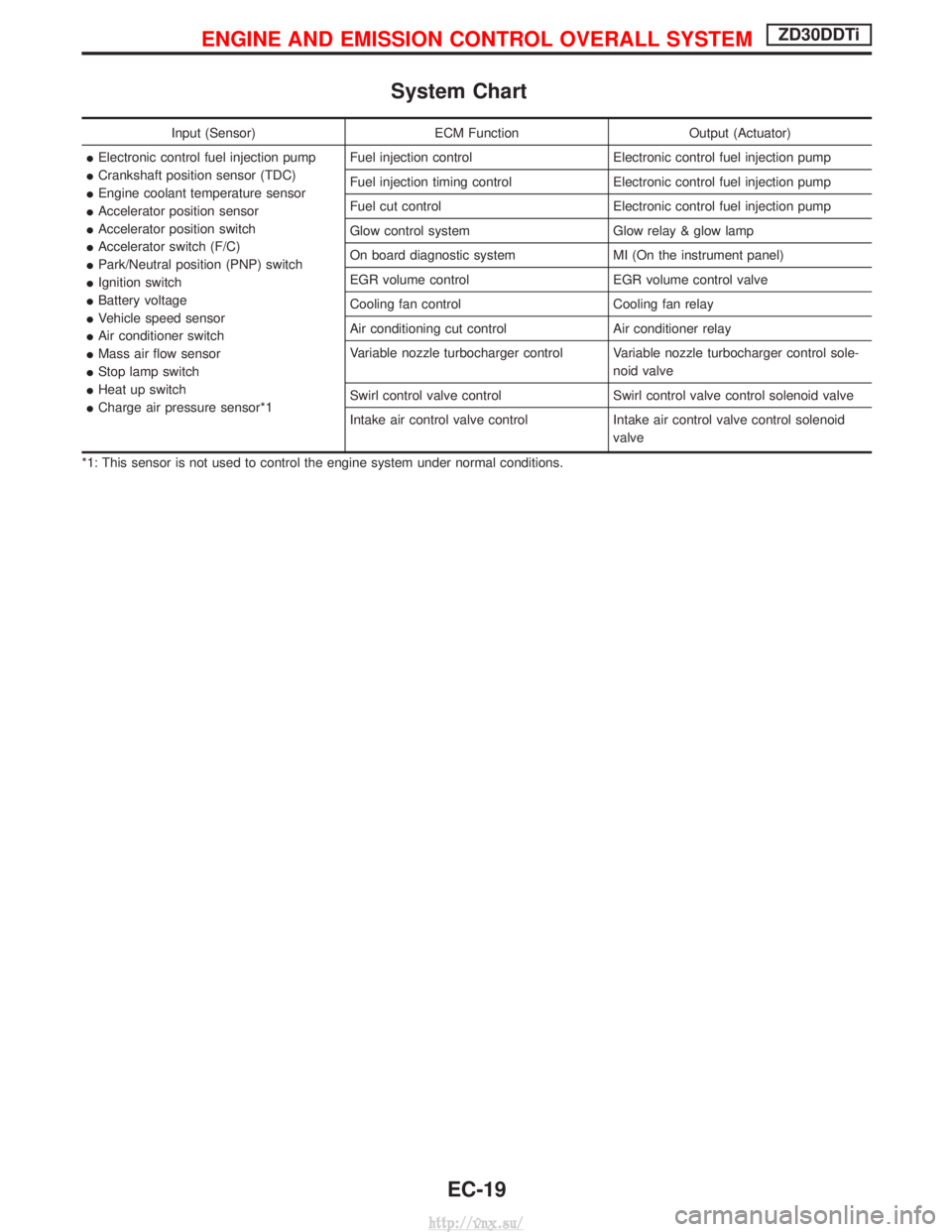
System Chart
Input (Sensor)ECM FunctionOutput (Actuator)
I Electronic control fuel injection pump
I Crankshaft position sensor (TDC)
I Engine coolant temperature sensor
I Accelerator position sensor
I Accelerator position switch
I Accelerator switch (F/C)
I Park/Neutral position (PNP) switch
I Ignition switch
I Battery voltage
I Vehicle speed sensor
I Air conditioner switch
I Mass air flow sensor
I Stop lamp switch
I Heat up switch
I Charge air pressure sensor*1 Fuel injection control
Electronic control fuel injection pump
Fuel injection timing control Electronic control fuel injection pump
Fuel cut control Electronic control fuel injection pump
Glow control system Glow relay & glow lamp
On board diagnostic system MI (On the instrument panel)
EGR volume control EGR volume control valve
Cooling fan control Cooling fan relay
Air conditioning cut control Air conditioner relay
Variable nozzle turbocharger control Variable nozzle turbocharger control sole- noid valve
Swirl control valve control Swirl control valve control solenoid valve
Intake air control valve control Intake air control valve control solenoid
valve
*1: This sensor is not used to control the engine system under normal conditions.
ENGINE AND EMISSION CONTROL OVERALL SYSTEMZD30DDTi
EC-19
http://vnx.su/
Page 297 of 1833
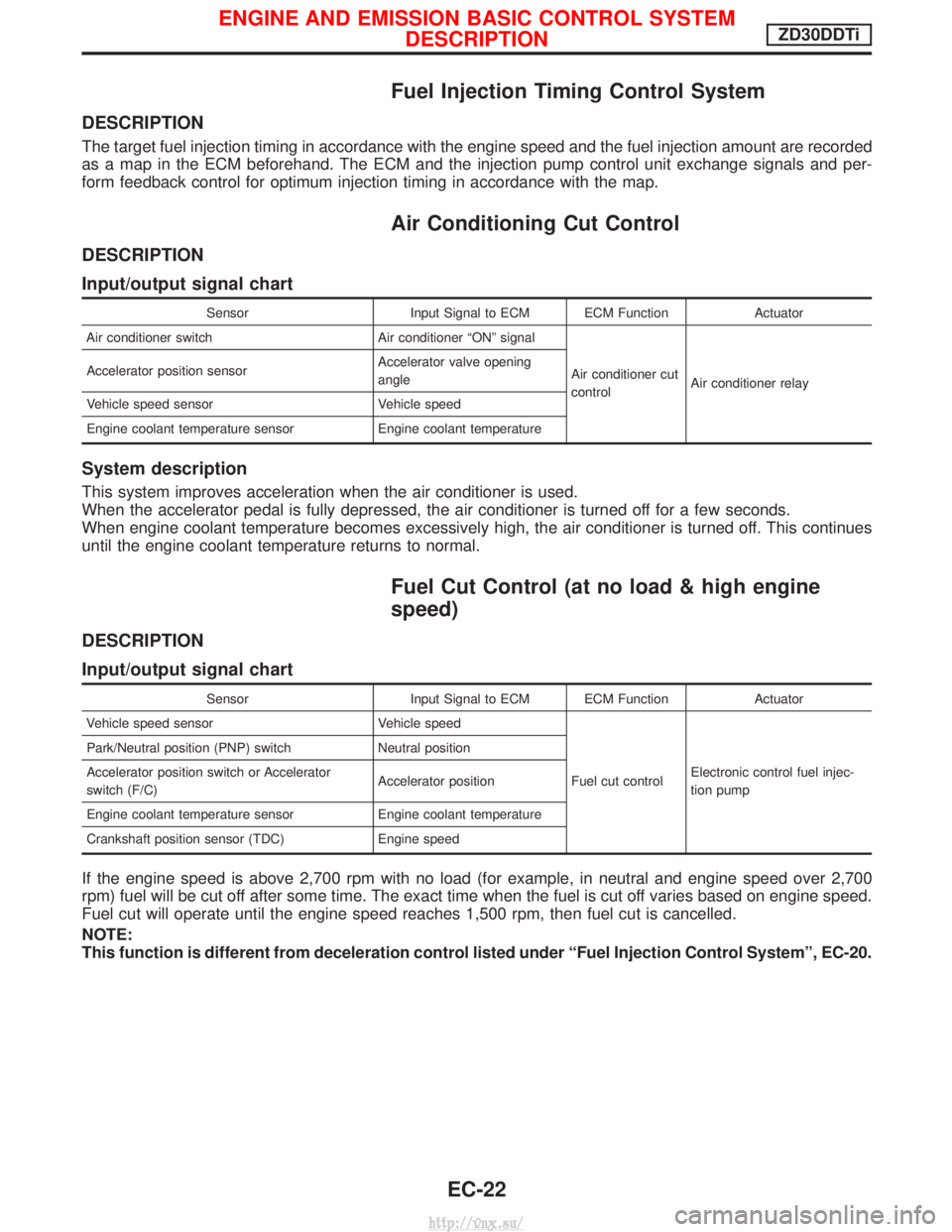
Fuel Injection Timing Control System
DESCRIPTION
The target fuel injection timing in accordance with the engine speed and the fuel injection amount are recorded
as a map in the ECM beforehand. The ECM and the injection pump control unit exchange signals and per-
form feedback control for optimum injection timing in accordance with the map.
Air Conditioning Cut Control
DESCRIPTION
Input/output signal chart
SensorInput Signal to ECM ECM Function Actuator
Air conditioner switch Air conditioner ªONº signal
Air conditioner cut
controlAir conditioner relay
Accelerator position sensor
Accelerator valve opening
angle
Vehicle speed sensor Vehicle speed
Engine coolant temperature sensor Engine coolant temperature
System description
This system improves acceleration when the air conditioner is used.
When the accelerator pedal is fully depressed, the air conditioner is turned off for a few seconds.
When engine coolant temperature becomes excessively high, the air conditioner is turned off. This continues
until the engine coolant temperature returns to normal.
Fuel Cut Control (at no load & high engine
speed)
DESCRIPTION
Input/output signal chart
SensorInput Signal to ECM ECM Function Actuator
Vehicle speed sensor Vehicle speed
Fuel cut controlElectronic control fuel injec-
tion pump
Park/Neutral position (PNP) switch
Neutral position
Accelerator position switch or Accelerator
switch (F/C) Accelerator position
Engine coolant temperature sensor Engine coolant temperature
Crankshaft position sensor (TDC) Engine speed
If the engine speed is above 2,700 rpm with no load (for example, in neutral and engine speed over 2,700
rpm) fuel will be cut off after some time. The exact time when the fuel is cut off varies based on engine speed.
Fuel cut will operate until the engine speed reaches 1,500 rpm, then fuel cut is cancelled.
NOTE:
This function is different from deceleration control listed under ªFuel Injection Control Systemº, EC-20.
ENGINE AND EMISSION BASIC CONTROL SYSTEM
DESCRIPTIONZD30DDTi
EC-22
http://vnx.su/
Page 603 of 1833
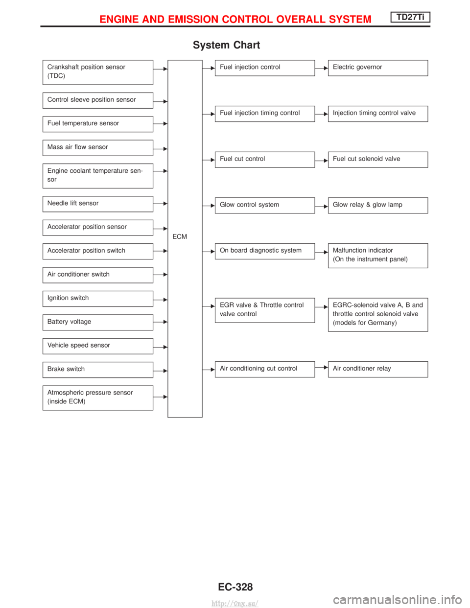
System Chart
Crankshaft position sensor
(TDC)E
ECM
Control sleeve position sensorE
Fuel temperature sensorE
Mass air flow sensorE
Engine coolant temperature sen-
sorE
Needle lift sensorE
Accelerator position sensorE
Accelerator position switchE
Air conditioner switchE
Ignition switchE
Battery voltageE
Vehicle speed sensorE
Brake switchE
Atmospheric pressure sensor
(inside ECM)E
EFuel injection controlEElectric governor
EFuel injection timing controlEInjection timing control valve
EFuel cut controlEFuel cut solenoid valve
EGlow control systemEGlow relay & glow lamp
EOn board diagnostic systemEMalfunction indicator
(On the instrument panel)
EEGR valve & Throttle control
valve controlEEGRC-solenoid valve A, B and
throttle control solenoid valve
(models for Germany)
EAir conditioning cut controlEAir conditioner relay
ENGINE AND EMISSION CONTROL OVERALL SYSTEMTD27Ti
EC-328
http://vnx.su/
Page 609 of 1833
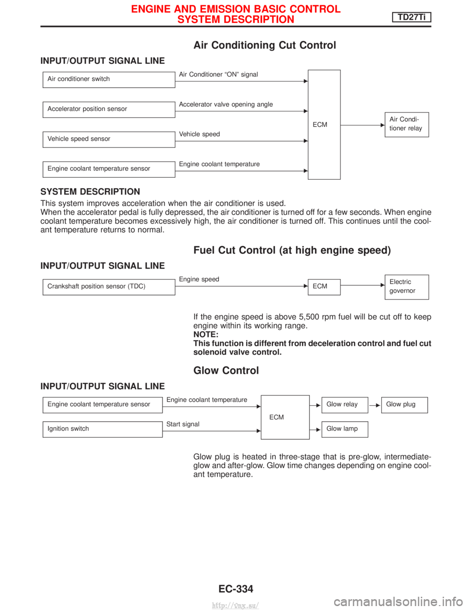
Air Conditioning Cut Control
INPUT/OUTPUT SIGNAL LINE
Air conditioner switchEAir Conditioner ªONº signalECM
EAir Condi-
tioner relay
Accelerator position sensorEAccelerator valve opening angle
Vehicle speed sensor
EVehicle speed
Engine coolant temperature sensor
EEngine coolant temperature
SYSTEM DESCRIPTION
This system improves acceleration when the air conditioner is used.
When the accelerator pedal is fully depressed, the air conditioner is turned off for a few seconds. When engine
coolant temperature becomes excessively high, the air conditioner is turned off. This continues until the cool-
ant temperature returns to normal.
Fuel Cut Control (at high engine speed)
INPUT/OUTPUT SIGNAL LINE
Crankshaft position sensor (TDC)EEngine speed ECMEElectric
governor
If the engine speed is above 5,500 rpm fuel will be cut off to keep
engine within its working range.
NOTE:
This function is different from deceleration control and fuel cut
solenoid valve control.
Glow Control
INPUT/OUTPUT SIGNAL LINE
Engine coolant temperature sensorEEngine coolant temperature
ECMEGlow relayEGlow plug
Ignition switchEStart signalEGlow lamp
Glow plug is heated in three-stage that is pre-glow, intermediate-
glow and after-glow. Glow time changes depending on engine cool-
ant temperature.
ENGINE AND EMISSION BASIC CONTROLSYSTEM DESCRIPTIONTD27Ti
EC-334
http://vnx.su/
Page 1399 of 1833
Supplemental Restraint System (SRS) ªAIR
BAGº and ªSEAT BELT PRE-TENSIONERº
The Supplemental Restraint System such as ªAIR BAGº and ªSEAT BELT PRE-TENSIONERº used along with
a seat belt, helps to reduce the risk or severity of injury to the driver and front passenger for certain types of
collision. The SRS composition which is available to NISSAN MODEL R20 is as follows (The composition
varies according to the destination and optional equipment.):
IFor a frontal collision
The Supplemental Restraint System consists of driver air bag module (located in the center of the steer-
ing wheel), front passenger air bag module (located on the instrument panel on passenger side), front seat
belt pre-tensioners, a diagnosis sensor unit, warning lamp, wiring harness and spiral cable.
I For a side collision
The Supplemental Restraint System consists of front side air bag module (located in the outer side of front
seat), side air bag (satellite) sensor, diagnosis sensor unit (one of components of air bags for a frontal
collision), wiring harness, warning lamp (one of components of air bags for a frontal collision).
WARNING:
I To avoid rendering the SRS inoperative, which could increase the risk of personal injury or death
in the event of a collision which would result in air bag inflation, all maintenance should be per-
formed by an authorized NISSAN dealer.
I Improper maintenance, including incorrect removal and installation of the SRS, can lead to per-
sonal injury caused by unintentional activation of the system.
I Do not use electrical test equipment on any circuit related to the SRS unless instructed to in this
Service Manual. Spiral cable and wiring harnesses covered with yellow insulation tape either just
before the harness connectors or for the complete harness are related to the SRS.
Introduction
To prevent the ozone layer from being destroyed, the HFC-134a (R-134a) refrigerant has replaced the previ-
ously used CFC-12 (R-12).
The new and previous service tools, refrigerant, lubricant, etc. are not interchangeable due to differences in
their physical properties and characteristics.
Always service the HFC-134a (R-134a) air conditioning system using the specified tools, lubricant and
refrigerant, observing the following precautions:
PRECAUTIONS
HA-2
http://vnx.su/
Page 1401 of 1833
Precautions for Working with HFC-134a
(R-134a)
WARNING:I CFC-12 (R-12) refrigerant and HFC-134a (R-134a) refrigerant must never be mixed, even in the
smallest amounts, as they are incompatible with each other. If the refrigerants are mixed, com-
pressor failure is likely to occur.
I Use only specified lubrication oil for the HFC-134a (R-134a) A/C system and HFC-134a (R-134a)
components. If lubrication oil other than that specified is used, compressor failure is likely to
occur.
I The specified HFC-134a (R-134a) lubrication oil absorbs moisture from the atmosphere at a rapid
rate, therefore the following handling precautions must be observed:
a: When removing refrigerant components from a vehicle, immediately cap (seal) the component to minimize the entry of moisture from the atmosphere.
b: When installing refrigerant components to a vehicle, do not remove the caps (unseal) until just before connecting the components. Also, complete the connection of all refrigerant loop
components as quickly as possible to minimize the entry of moisture into the system.
c: Use the specified lubrication oil from a sealed container only. Containers must be re-sealed immediately after dispensing the lubrication oil. Lubrication oil in containers which are not
properly sealed will become moisture saturated, and such lubrication oil is no longer suitable
for use and should be properly disposed of.
d: Avoid breathing A/C refrigerant and lubricant vapor or mist. Exposure may irritate eyes, nose and throat. Use only approved recovery/recycling equipment to discharge HFC-134a (R-134a)
system. If accidental system discharge occurs, ventilate work area before resuming service.
Additional health and safety information may be obtained from refrigerant and lubricant
manufacturers.
e: Do not allow lubrication oil (Nissan A/C System Oil Type S or Type R) to come in contact with styrofoam parts. Damage may result.
General Refrigerant Precautions
WARNING:
I Do not release refrigerant into the air. Use approved recovery/recycling equipment to capture the
refrigerant every time an air conditioning system is discharged.
I Always wear eye and hand protection (goggles and gloves) when working with any refrigerant or
air conditioning system.
I Do not store or heat refrigerant containers above 52ÉC (125ÉF).
I Do not heat a refrigerant container with an open flame; if container warming is required, place the
bottom of the container in a warm pail of water.
I Do not drop, puncture, or incinerate refrigerant containers.
I Keep refrigerant away from open flames: poisonous gas will be produced if refrigerant burns.
I Refrigerant will displace oxygen, therefore be certain to work in well ventilated areas to prevent
suffocation.
I Do not introduce compressed air to any refrigerant container or refrigerant component.
PRECAUTIONS
HA-4
http://vnx.su/
Page 1414 of 1833
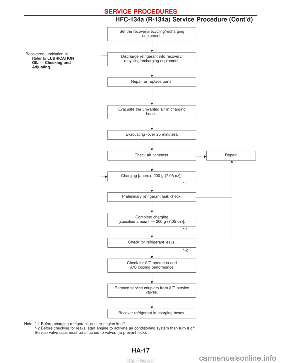
Set the recovery/recycling/rechargingequipment.
Recovered lubrication oilRefer to LUBRICATION
OIL Ð Checking and
Adjusting. Discharge refrigerant into recovery/
recycling/recharging equipment.
Repair or replace parts.
Evacuate the unwanted air in charging hoses.
Evacuating (over 25 minutes).
Check air tightness.ERepair.
G
ECharging [approx. 200 g (7.05 oz)].
*-1
Preliminary refrigerant leak check.
Complete charging
[specified amount Ð 200 g (7.05 oz)].
*-1
Check for refrigerant leaks.
*-2
Check for A/C operation and A/C cooling performance
Remove service couplers from A/C service valves.
Recover refrigerant in charging hoses.
Note: *-1 Before charging refrigerant, ensure engine is off.*-2 Before checking for leaks, start engine to activate air conditioning system then turn it off.
Service valve caps must be attached to valves (to prevent leak).
H
H
H
H
H
H
H
H
H
H
H
H
SERVICE PROCEDURES
HFC-134a (R-134a) Service Procedure (Cont'd)
HA-17
http://vnx.su/
Page 1432 of 1833
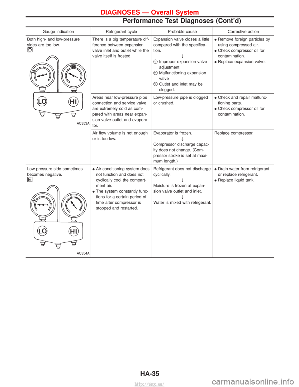
Gauge indicationRefrigerant cycleProbable causeCorrective action
Both high- and low-pressure
sides are too low.
AC353A
There is a big temperature dif-
ference between expansion
valve inlet and outlet while the
valve itself is frosted. Expansion valve closes a little
compared with the specifica-
tion.
"
q
1Improper expansion valve
adjustment
q
2Malfunctioning expansion
valve
q
3Outlet and inlet may be
clogged. I
Remove foreign particles by
using compressed air.
I Check compressor oil for
contamination.
I Replace expansion valve.
Areas near low-pressure pipe
connection and service valve
are extremely cold as com-
pared with areas near expan-
sion valve outlet and evapora-
tor. Low-pressure pipe is clogged
or crushed.
I
Check and repair malfunc-
tioning parts.
I Check compressor oil for
contamination.
Air flow volume is not enough
or is too low. Evaporator is frozen.
"
Compressor discharge capac-
ity does not change. (Com-
pressor stroke is set at maxi-
mum length.) Replace compressor.
Low-pressure side sometimes
becomes negative.
AC354A
I Air conditioning system does
not function and does not
cyclically cool the compart-
ment air.
I The system constantly func-
tions for a certain period of
time after compressor is
stopped and restarted. Refrigerant does not discharge
cyclically.
"
Moisture is frozen at expan-
sion valve outlet and inlet. "
Water is mixed with refrigerant. I
Drain water from refrigerant
or replace refrigerant.
I Replace liquid tank.
DIAGNOSES Ð Overall System
Performance Test Diagnoses (Cont'd)
HA-35
http://vnx.su/