ECU NISSAN TERRANO 2004 Service Repair Manual
[x] Cancel search | Manufacturer: NISSAN, Model Year: 2004, Model line: TERRANO, Model: NISSAN TERRANO 2004Pages: 1833, PDF Size: 53.42 MB
Page 7 of 1833
insulation (either just before the harness connectors or for
the complete harness), for easy identification.
Precautions for NATS
NATS (Nissan Anti-Theft System)
NATS will immobilize the engine if someone tries to start it without
the registered key of NATS.
Both of the originally supplied ignition key IDs have been NATS
registered.
The NATS security indicator is located on the instrument panel. The
indicator blinks when the ignition switch is in ªOFFº or ªACCº posi-
tion. Therefore, NATS warns outsiders that the vehicle is equipped
with the anti-theft system.
IWhen NATS detects trouble, the malfunction indicator lamp
(MIL) blinks.
This blinking indicates that the anti-theft is not functioning, so
prompt service is required.
I If the malfunction indicator lamp comes on while the engine is
running, return the vehicle to the workshop before turning the
ignition switch ªOFFº.
Once the ignition switch is turned ªOFFº, the engine can not be
started.
I When servicing NATS (trouble diagnoses, system initialization
and additional registration of other NATS ignition key IDs) CON-
SULT-II hardware and CONSULT-II NATS software is neces-
sary.
Regarding the procedures of NATS initialization and NATS igni-
tion key ID registration, refer to CONSULT-II operation manual,
NATS.
Therefore, CONSULT-II NATS software (program card and
operation manual) must be kept strictly confidential to main-
tain the integrity of the anti-theft function.
I When servicing NATS (trouble diagnoses, system initialization
and additional registration of other NATS ignition key IDs), it
may be necessary to re-register original key identification.
Therefore, be sure to receive all keys from vehicle owner.
A maximum of five key IDs can be registered into NATS.
I When failing to start the engine first-time using the key of
NATS, starts as follows:
(1) Turn ignition key to ªOFFº.
(2) Wait approx. 5 seconds.
(3) Turn ignition key to ªSTARTº again while keeping the key
apart from any others on key-chain.
SGI916
PRECAUTIONS
Supplemental Restraint System (SRS) ªAIR
BAGº and ªSEAT BELT PRE-TENSIONERº
(Dual Air Bag System) (Cont'd)
GI-4
http://vnx.su/
Page 29 of 1833
Function and System Application
Diagnostictest mode Function ENGINE A/T Air bag ABS NATS*1
Self-diagnostic results Self-diagnostic results can be read and erased quickly. xxxxx
ECU discriminated No. Classification number of a replacement ECU can be
read to prevent an incorrect ECU from being installed. ÐÐxÐÐ
Data monitor Input/Output data in the ECM can be read. x xÐxÐ
Active test Diagnostic Test Mode in which CONSULT-II drives
some actuators apart from the ECMs and also shifts
some parameters in a specified range. xÐÐxÐ
ECU (ECM) part number ECU (ECM) part number can be read. x xÐxÐ
Control unit initialisation All registered ignition key IDs in NATS components can
be initialised and new IDs can be registered. ÐÐÐÐ x
Self-function check ECM checks its own NATS communication interface. ÐÐÐÐ x
x: Applicable
*1: NATS: Nissan Anti-Theft System
Nickel Metal Hydride Battery Replacement
CONSULT-II contains a nickel metal hydride battery. When replacing the battery obey the following:
WARNING:
Replace the nickel metal hydride battery with genuine CONSULT-II battery only. Use of another battery
may present a risk of fire or explosion. The battery may present a fire or chemical burn hazard if mis-
treated. Do not recharge, disassemble of dispose of in fire.
Keep the battery out of reach of children and discard used battery conforming to the local regulations.
Checking Equipment
When ordering this equipment, contact your NISSAN distributor.
Tool name Description
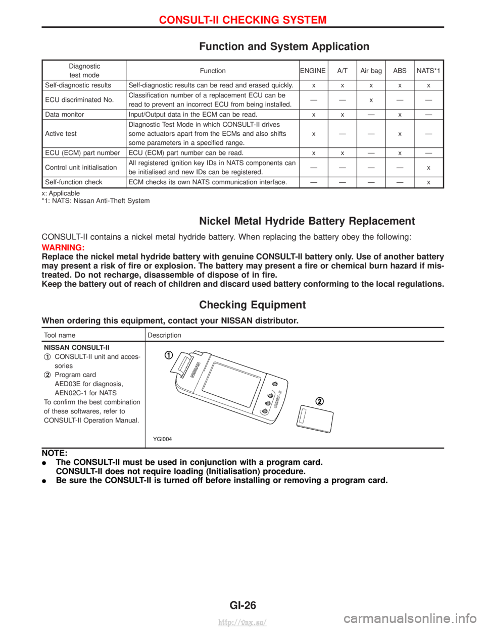
NISSAN CONSULT-II
q
1CONSULT-II unit and acces-
sories
q
2Program card
AED03E for diagnosis,
AEN02C-1 for NATS
To confirm the best combination
of these softwares, refer to
CONSULT-II Operation Manual.
YGI004
NOTE:
I The CONSULT-II must be used in conjunction with a program card.
CONSULT-II does not require loading (Initialisation) procedure.
I Be sure the CONSULT-II is turned off before installing or removing a program card.
CONSULT-II CHECKING SYSTEM
GI-26
http://vnx.su/
Page 35 of 1833
4-pole Lift
WARNING:
Do not use a 2-pole lift.
Due to weight balance of the vehicle and shape of underbody,
lift arms can not be attached in a safe way. Therefore it is rec-
ommended to use a 4-pole lift only.
Tow Truck Towing
CAUTION:
IAll applicable local laws regarding the towing operation
must be obeyed.
I It is necessary to use proper towing equipment to avoid
possible damage to the vehicle during a towing operation.
I Attach safety chains for all towing.
I When towing, make sure that the transmission, steering
system and power train are in good order. If any unit is
damaged, a dolly must be used.
I When towing with the front wheels on the ground:
Move both the gearshift and transfer levers to neutral (ªNº
position).
Turn the ignition key to the ªOFFº position and secure the
steering wheel in a straightahead position with a rope or
similar device. Never place the ignition key in the ªLOCKº
position. This will result in damage to the steering lock
mechanism.
I When towing with the rear wheels on the ground, release
the parking brake and move both the gearshift and trans-
fer levers to neutral (ªNº position).
I Never tow vehicle from the rear (i.e., backward) with four
wheels on the ground as this may cause serious and
expensive damage to the transmission.
LIFTING POINTS AND TOW TRUCK TOWING
GI-32
http://vnx.su/
Page 36 of 1833
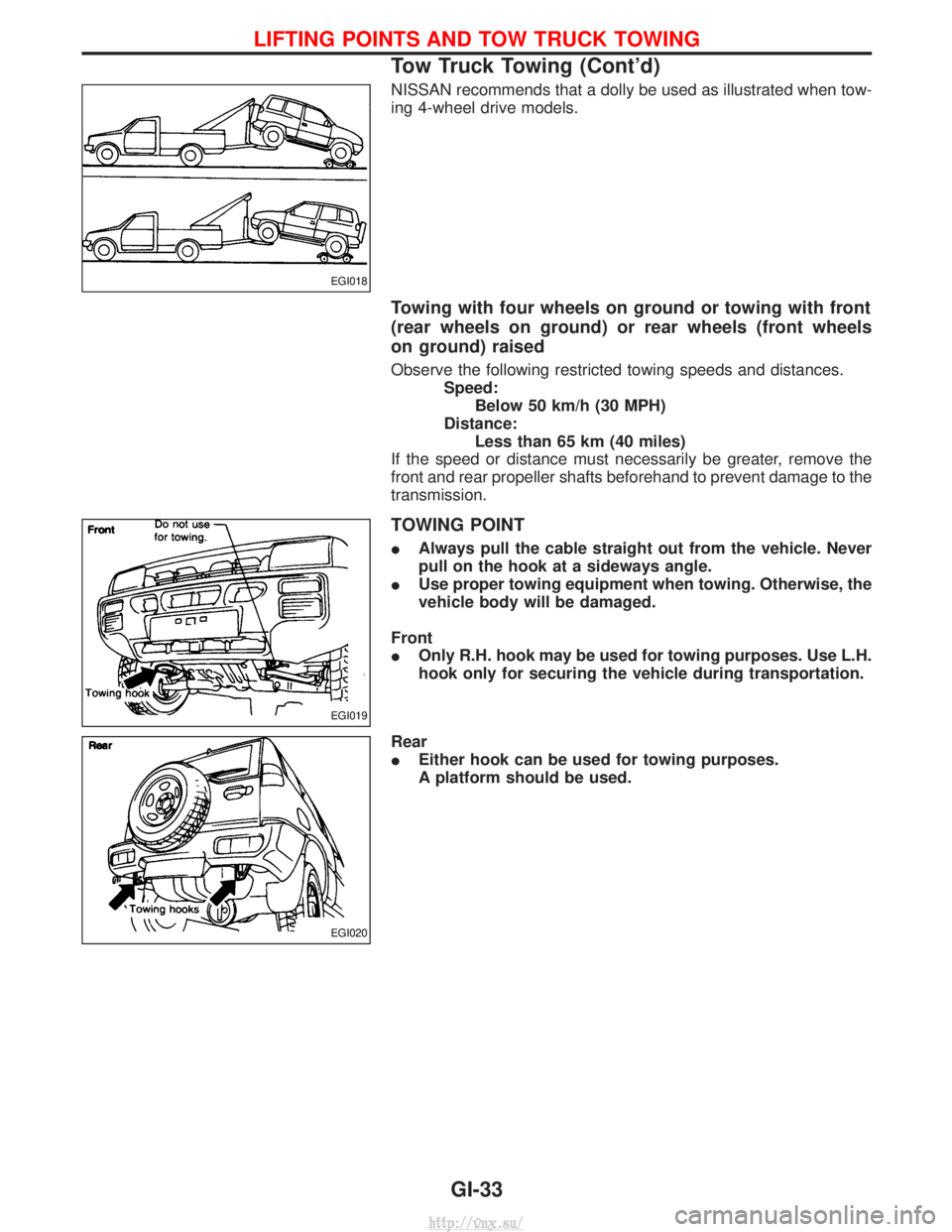
NISSAN recommends that a dolly be used as illustrated when tow-
ing 4-wheel drive models.
Towing with four wheels on ground or towing with front
(rear wheels on ground) or rear wheels (front wheels
on ground) raised
Observe the following restricted towing speeds and distances.Speed:Below 50 km/h (30 MPH)
Distance: Less than 65 km (40 miles)
If the speed or distance must necessarily be greater, remove the
front and rear propeller shafts beforehand to prevent damage to the
transmission.
TOWING POINT
I Always pull the cable straight out from the vehicle. Never
pull on the hook at a sideways angle.
I Use proper towing equipment when towing. Otherwise, the
vehicle body will be damaged.
Front
I Only R.H. hook may be used for towing purposes. Use L.H.
hook only for securing the vehicle during transportation.
Rear
I Either hook can be used for towing purposes.
A platform should be used.
EGI018
EGI019
EGI020
LIFTING POINTS AND TOW TRUCK TOWING
Tow Truck Towing (Cont'd)
GI-33
http://vnx.su/
Page 45 of 1833
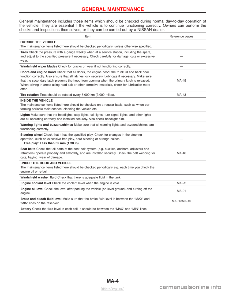
General maintenance includes those items which should be checked during normal day-to-day operation of
the vehicle. They are essential if the vehicle is to continue functioning correctly. Owners can perform the
checks and inspections themselves, or they can be carried out by a NISSAN dealer.
ItemReference pages
OUTSIDE THE VEHICLE
The maintenance items listed here should be checked periodically, unless otherwise specified.
Tires Check the pressure with a gauge weekly when at a service station, including the spare,
and adjust to the specified pressure if necessary. Check carefully for damage, cuts or excessive
wear. Ð
Windshield wiper blades Check for cracks or wear if not functioning correctly. Ð
Doors and engine hood Check that all doors, the engine hood, the trunk lid and back door
function correctly. Also ensure that all latches lock securely. Lubricate if necessary. Make sure
that the secondary latch prevents the hood from opening when the primary latch is released.
When driving in areas using road salt or other corrosive materials, check for lubrication more
often. MA-45
Tire rotation Tires should be rotated every 5,000 km (3,000 miles). MA-43
INSIDE THE VEHICLE
The maintenance items listed here should be checked on a regular basis, such as when per-
forming periodic maintenance, cleaning the vehicle etc.
Lights Make sure that the headlights, stop lights, tail lights, turn signal lights, and other lights
are all operating correctly and installed securely. Also check headlight aim. Ð
Warning lights and buzzers/chimes Make sure that all warning lights and buzzers/chimes are
functioning correctly. Ð
Steering wheel Check that it has the specified play. Check for changes in the steering
operation, such as excessive free play, hard steering or strange noises. Free play: Less than 35 mm (1.38 in) Ð
Seat belts Check that all parts of the seat belt system (e.g. buckles, anchors, adjusters and
retractors) operate properly and smoothly, and are installed securely. Check the belt webbing for
cuts, fraying, wear of damage. MA-46
UNDER THE HOOD AND VEHICLE
The maintenance items listed here should be checked periodically e.g. each time you check the
engine oil or refuel.
Windshield washer fluid Check that there is adequate fluid in the tank.
Engine coolant level Check the coolant level when the engine is cold. MA-22
Engine oil level Check the level after parking the vehicle (on level ground) and turning off the
engine. MA-21
Brake and clutch fluid level Make sure that the brake fluid level is between the ªMAXº and
ªMINº lines on the reservoir. MA-36/MA-40
Battery Check the fluid level in each cell. It should be between the ªMAXº and ªMINº lines. Ð
GENERAL MAINTENANCE
MA-4
http://vnx.su/
Page 63 of 1833
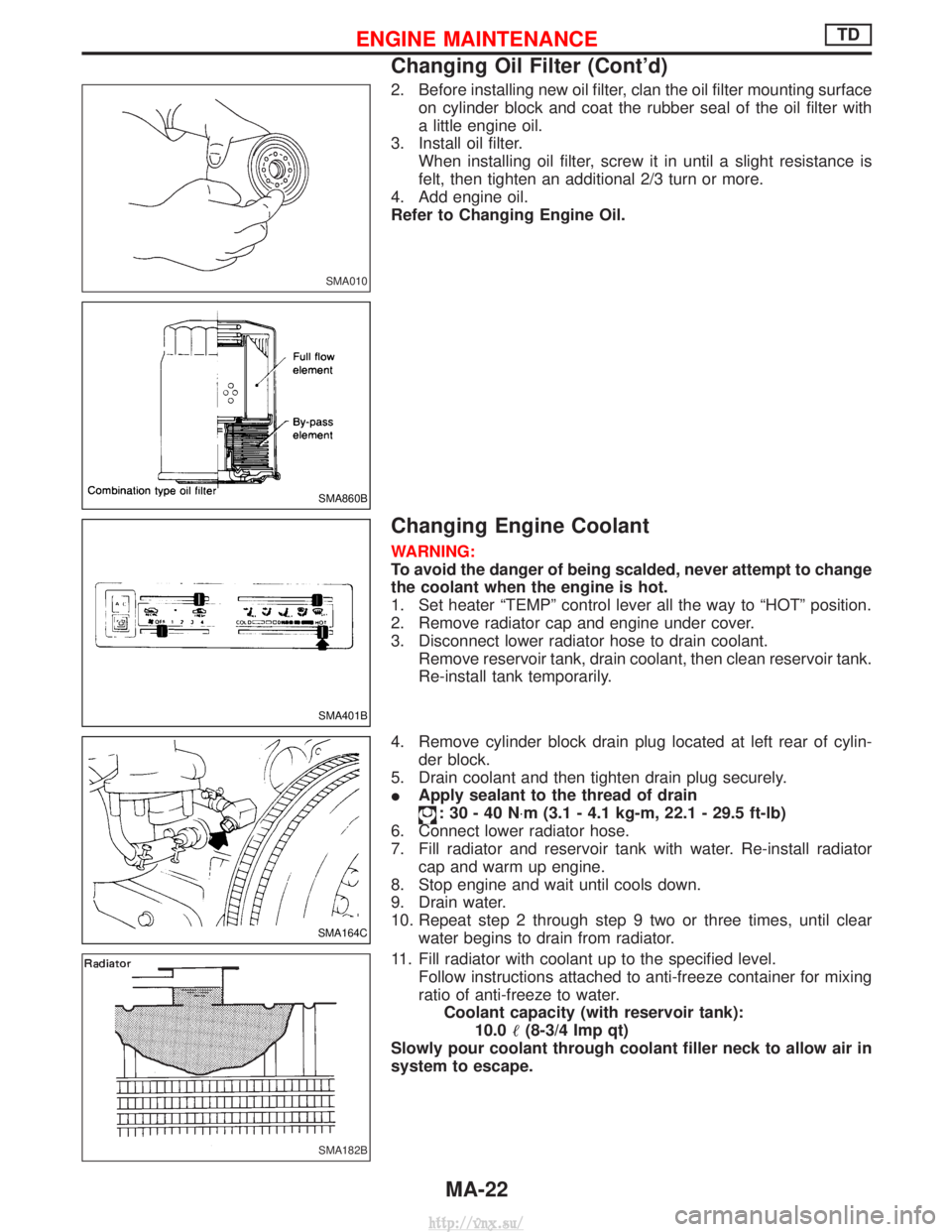
2. Before installing new oil filter, clan the oil filter mounting surfaceon cylinder block and coat the rubber seal of the oil filter with
a little engine oil.
3. Install oil filter. When installing oil filter, screw it in until a slight resistance is
felt, then tighten an additional 2/3 turn or more.
4. Add engine oil.
Refer to Changing Engine Oil.
Changing Engine Coolant
WARNING:
To avoid the danger of being scalded, never attempt to change
the coolant when the engine is hot.
1. Set heater ªTEMPº control lever all the way to ªHOTº position.
2. Remove radiator cap and engine under cover.
3. Disconnect lower radiator hose to drain coolant. Remove reservoir tank, drain coolant, then clean reservoir tank.
Re-install tank temporarily.
4. Remove cylinder block drain plug located at left rear of cylin- der block.
5. Drain coolant and then tighten drain plug securely.
I Apply sealant to the thread of drain
:30-40N ×m (3.1 - 4.1 kg-m, 22.1 - 29.5 ft-lb)
6. Connect lower radiator hose.
7. Fill radiator and reservoir tank with water. Re-install radiator cap and warm up engine.
8. Stop engine and wait until cools down.
9. Drain water.
10. Repeat step 2 through step 9 two or three times, until clear water begins to drain from radiator.
11. Fill radiator with coolant up to the specified level. Follow instructions attached to anti-freeze container for mixing
ratio of anti-freeze to water.Coolant capacity (with reservoir tank): 10.0 (8-3/4 Imp qt)
Slowly pour coolant through coolant filler neck to allow air in
system to escape.
SMA010
SMA860B
SMA401B
SMA164C
SMA182B
ENGINE MAINTENANCETD
Changing Oil Filter (Cont'd)
MA-22
http://vnx.su/
Page 67 of 1833
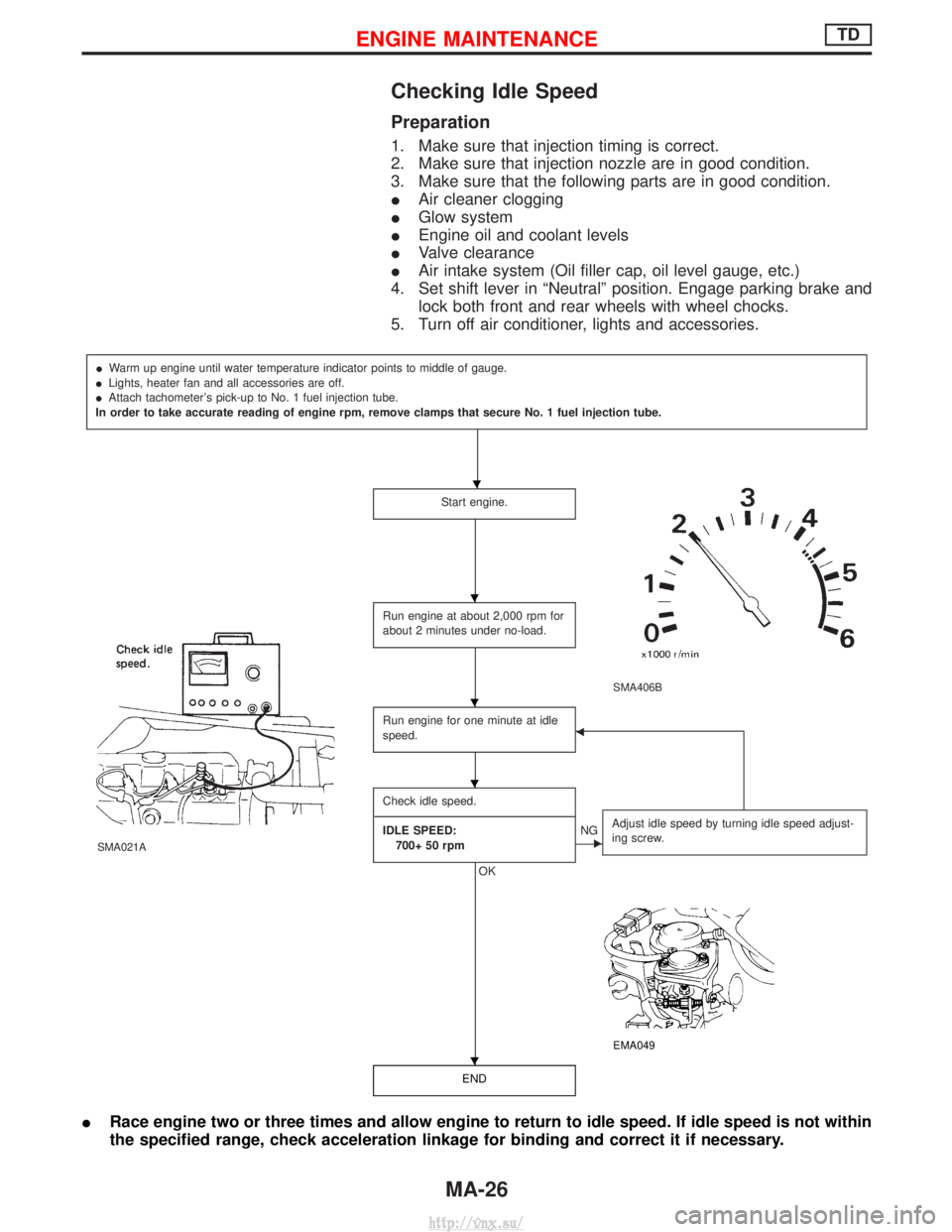
Checking Idle Speed
Preparation
1. Make sure that injection timing is correct.
2. Make sure that injection nozzle are in good condition.
3. Make sure that the following parts are in good condition.
IAir cleaner clogging
I Glow system
I Engine oil and coolant levels
I Valve clearance
I Air intake system (Oil filler cap, oil level gauge, etc.)
4. Set shift lever in ªNeutralº position. Engage parking brake and lock both front and rear wheels with wheel chocks.
5. Turn off air conditioner, lights and accessories.
I Warm up engine until water temperature indicator points to middle of gauge.
I Lights, heater fan and all accessories are off.
I Attach tachometer's pick-up to No. 1 fuel injection tube.
In order to take accurate reading of engine rpm, remove clamps that secure No. 1 fuel injection tube.
Start engine.
SMA406B
SMA021A
Run engine at about 2,000 rpm for
about 2 minutes under no-load.
Run engine for one minute at idle
speed.F
Check idle speed.
---------------------------------------------------------------------------------------------------------------------------------------------------------------------------------------------------------------------------------- IDLE SPEED: 700+ 50 rpm
OK
ENG Adjust idle speed by turning idle speed adjust-
ing screw.
EMA049
END
I
Race engine two or three times and allow engine to return to idle speed. If idle speed is not within
the specified range, check acceleration linkage for binding and correct it if necessary.
H
H
H
H
H
ENGINE MAINTENANCETD
MA-26
http://vnx.su/
Page 70 of 1833
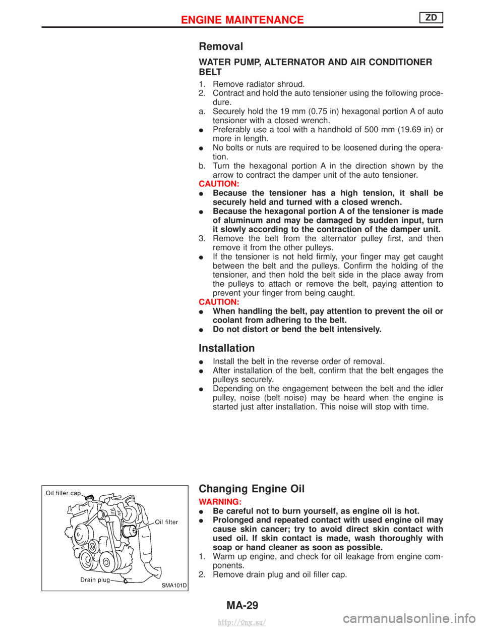
Removal
WATER PUMP, ALTERNATOR AND AIR CONDITIONER
BELT
1. Remove radiator shroud.
2. Contract and hold the auto tensioner using the following proce-dure.
a. Securely hold the 19 mm (0.75 in) hexagonal portion A of auto tensioner with a closed wrench.
I Preferably use a tool with a handhold of 500 mm (19.69 in) or
more in length.
I No bolts or nuts are required to be loosened during the opera-
tion.
b. Turn the hexagonal portion A in the direction shown by the arrow to contract the damper unit of the auto tensioner.
CAUTION:
I Because the tensioner has a high tension, it shall be
securely held and turned with a closed wrench.
I Because the hexagonal portion A of the tensioner is made
of aluminum and may be damaged by sudden input, turn
it slowly according to the contraction of the damper unit.
3. Remove the belt from the alternator pulley first, and then remove it from the other pulleys.
I If the tensioner is not held firmly, your finger may get caught
between the belt and the pulleys. Confirm the holding of the
tensioner, and then hold the belt side in the place away from
the pulleys to attach or remove the belt, paying attention to
prevent your finger from being caught.
CAUTION:
I When handling the belt, pay attention to prevent the oil or
coolant from adhering to the belt.
I Do not distort or bend the belt intensively.
Installation
IInstall the belt in the reverse order of removal.
I After installation of the belt, confirm that the belt engages the
pulleys securely.
I Depending on the engagement between the belt and the idler
pulley, noise (belt noise) may be heard when the engine is
started just after installation. This noise will stop with time.
Changing Engine Oil
WARNING:
IBe careful not to burn yourself, as engine oil is hot.
I Prolonged and repeated contact with used engine oil may
cause skin cancer; try to avoid direct skin contact with
used oil. If skin contact is made, wash thoroughly with
soap or hand cleaner as soon as possible.
1. Warm up engine, and check for oil leakage from engine com- ponents.
2. Remove drain plug and oil filler cap.
SMA101D
ENGINE MAINTENANCEZD
MA-29
http://vnx.su/
Page 72 of 1833
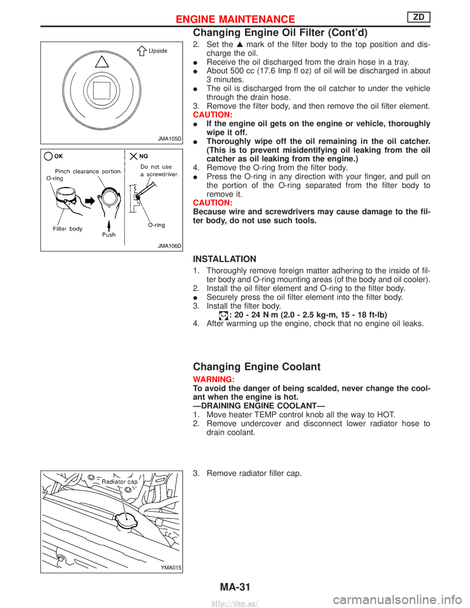
2. Set theGmark of the filter body to the top position and dis-
charge the oil.
I Receive the oil discharged from the drain hose in a tray.
I About 500 cc (17.6 Imp fl oz) of oil will be discharged in about
3 minutes.
I The oil is discharged from the oil catcher to under the vehicle
through the drain hose.
3. Remove the filter body, and then remove the oil filter element.
CAUTION:
I If the engine oil gets on the engine or vehicle, thoroughly
wipe it off.
I Thoroughly wipe off the oil remaining in the oil catcher.
(This is to prevent misidentifying oil leaking from the oil
catcher as oil leaking from the engine.)
4. Remove the O-ring from the filter body.
I Press the O-ring in any direction with your finger, and pull on
the portion of the O-ring separated from the filter body to
remove it.
CAUTION:
Because wire and screwdrivers may cause damage to the fil-
ter body, do not use such tools.
INSTALLATION
1. Thoroughly remove foreign matter adhering to the inside of fil- ter body and O-ring mounting areas (of the body and oil cooler).
2. Install the oil filter element and O-ring to the filter body.
I Securely press the oil filter element into the filter body.
3. Install the filter body.
:20-24N ×m (2.0 - 2.5 kg-m, 15 - 18 ft-lb)
4. After warming up the engine, check that no engine oil leaks.
Changing Engine Coolant
WARNING:
To avoid the danger of being scalded, never change the cool-
ant when the engine is hot.
ÐDRAINING ENGINE COOLANTÐ
1. Move heater TEMP control knob all the way to HOT.
2. Remove undercover and disconnect lower radiator hose to drain coolant.
3. Remove radiator filler cap.
JMA105D
JMA106D
YMA015
ENGINE MAINTENANCEZD
Changing Engine Oil Filter (Cont'd)
MA-31
http://vnx.su/
Page 85 of 1833
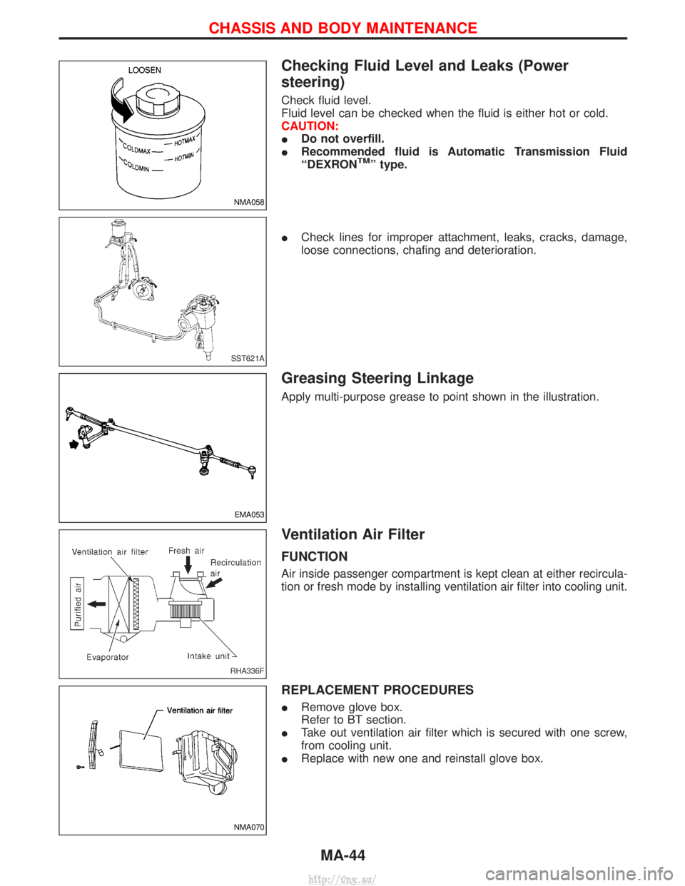
Checking Fluid Level and Leaks (Power
steering)
Check fluid level.
Fluid level can be checked when the fluid is either hot or cold.
CAUTION:
IDo not overfill.
I Recommended fluid is Automatic Transmission Fluid
ªDEXRON
TMº type.
I Check lines for improper attachment, leaks, cracks, damage,
loose connections, chafing and deterioration.
Greasing Steering Linkage
Apply multi-purpose grease to point shown in the illustration.
Ventilation Air Filter
FUNCTION
Air inside passenger compartment is kept clean at either recircula-
tion or fresh mode by installing ventilation air filter into cooling unit.
REPLACEMENT PROCEDURES
IRemove glove box.
Refer to BT section.
I Take out ventilation air filter which is secured with one screw,
from cooling unit.
I Replace with new one and reinstall glove box.
NMA058
SST621A
EMA053
RHA336F
NMA070
CHASSIS AND BODY MAINTENANCE
MA-44
http://vnx.su/